US6902575B2 - Stent delivery apparatus and method - Google Patents
Stent delivery apparatus and method Download PDFInfo
- Publication number
- US6902575B2 US6902575B2 US10/025,669 US2566901A US6902575B2 US 6902575 B2 US6902575 B2 US 6902575B2 US 2566901 A US2566901 A US 2566901A US 6902575 B2 US6902575 B2 US 6902575B2
- Authority
- US
- United States
- Prior art keywords
- stent
- outer tube
- sleeve
- inner tube
- distal end
- Prior art date
- Legal status (The legal status is an assumption and is not a legal conclusion. Google has not performed a legal analysis and makes no representation as to the accuracy of the status listed.)
- Expired - Fee Related, expires
Links
- 238000000034 method Methods 0.000 title claims abstract description 23
- 230000000903 blocking effect Effects 0.000 claims abstract description 27
- 239000012530 fluid Substances 0.000 claims description 3
- 239000002985 plastic film Substances 0.000 claims 1
- 229920006255 plastic film Polymers 0.000 claims 1
- 239000000463 material Substances 0.000 description 11
- 239000011248 coating agent Substances 0.000 description 4
- 238000000576 coating method Methods 0.000 description 4
- 238000003780 insertion Methods 0.000 description 4
- 230000037431 insertion Effects 0.000 description 4
- 210000001124 body fluid Anatomy 0.000 description 3
- 239000007787 solid Substances 0.000 description 3
- JVTAAEKCZFNVCJ-UWTATZPHSA-N D-lactic acid Chemical compound C[C@@H](O)C(O)=O JVTAAEKCZFNVCJ-UWTATZPHSA-N 0.000 description 2
- 208000031481 Pathologic Constriction Diseases 0.000 description 2
- 230000004075 alteration Effects 0.000 description 2
- 210000004204 blood vessel Anatomy 0.000 description 2
- 230000036760 body temperature Effects 0.000 description 2
- 229940022769 d- lactic acid Drugs 0.000 description 2
- 238000011010 flushing procedure Methods 0.000 description 2
- 230000006870 function Effects 0.000 description 2
- 239000000017 hydrogel Substances 0.000 description 2
- 230000006872 improvement Effects 0.000 description 2
- 238000011065 in-situ storage Methods 0.000 description 2
- 238000004519 manufacturing process Methods 0.000 description 2
- 230000007246 mechanism Effects 0.000 description 2
- 239000002184 metal Substances 0.000 description 2
- 238000012986 modification Methods 0.000 description 2
- 230000004048 modification Effects 0.000 description 2
- HLXZNVUGXRDIFK-UHFFFAOYSA-N nickel titanium Chemical compound [Ti].[Ti].[Ti].[Ti].[Ti].[Ti].[Ti].[Ti].[Ti].[Ti].[Ti].[Ni].[Ni].[Ni].[Ni].[Ni].[Ni].[Ni].[Ni].[Ni].[Ni].[Ni].[Ni].[Ni].[Ni] HLXZNVUGXRDIFK-UHFFFAOYSA-N 0.000 description 2
- 229910001000 nickel titanium Inorganic materials 0.000 description 2
- 229920000139 polyethylene terephthalate Polymers 0.000 description 2
- 229920000642 polymer Polymers 0.000 description 2
- 208000037804 stenosis Diseases 0.000 description 2
- 230000036262 stenosis Effects 0.000 description 2
- 239000013589 supplement Substances 0.000 description 2
- 238000004804 winding Methods 0.000 description 2
- 229930182843 D-Lactic acid Natural products 0.000 description 1
- 239000004677 Nylon Substances 0.000 description 1
- 229920000954 Polyglycolide Polymers 0.000 description 1
- FAPWRFPIFSIZLT-UHFFFAOYSA-M Sodium chloride Chemical compound [Na+].[Cl-] FAPWRFPIFSIZLT-UHFFFAOYSA-M 0.000 description 1
- 239000000853 adhesive Substances 0.000 description 1
- 230000001070 adhesive effect Effects 0.000 description 1
- 229910045601 alloy Inorganic materials 0.000 description 1
- 239000000956 alloy Substances 0.000 description 1
- 238000005452 bending Methods 0.000 description 1
- 210000000013 bile duct Anatomy 0.000 description 1
- 210000001072 colon Anatomy 0.000 description 1
- 150000001875 compounds Chemical class 0.000 description 1
- 229940039231 contrast media Drugs 0.000 description 1
- 239000002872 contrast media Substances 0.000 description 1
- 230000010339 dilation Effects 0.000 description 1
- 230000005489 elastic deformation Effects 0.000 description 1
- 229920001971 elastomer Polymers 0.000 description 1
- 239000000806 elastomer Substances 0.000 description 1
- 238000002513 implantation Methods 0.000 description 1
- 230000000977 initiatory effect Effects 0.000 description 1
- 238000002347 injection Methods 0.000 description 1
- 239000007924 injection Substances 0.000 description 1
- 239000000203 mixture Substances 0.000 description 1
- 229920001778 nylon Polymers 0.000 description 1
- 229920003023 plastic Polymers 0.000 description 1
- 239000004033 plastic Substances 0.000 description 1
- 229920001432 poly(L-lactide) Polymers 0.000 description 1
- 229920000747 poly(lactic acid) Polymers 0.000 description 1
- -1 poly(lactic acid-ethylene oxide) copolymers Polymers 0.000 description 1
- 229920002463 poly(p-dioxanone) polymer Polymers 0.000 description 1
- 229920001610 polycaprolactone Polymers 0.000 description 1
- 239000004632 polycaprolactone Substances 0.000 description 1
- 239000000622 polydioxanone Substances 0.000 description 1
- 239000004633 polyglycolic acid Substances 0.000 description 1
- 239000004626 polylactic acid Substances 0.000 description 1
- 230000008569 process Effects 0.000 description 1
- 230000000284 resting effect Effects 0.000 description 1
- 239000012781 shape memory material Substances 0.000 description 1
- 239000011780 sodium chloride Substances 0.000 description 1
- 238000005728 strengthening Methods 0.000 description 1
- 239000000126 substance Substances 0.000 description 1
- 230000000930 thermomechanical effect Effects 0.000 description 1
- 210000003437 trachea Anatomy 0.000 description 1
- 210000000626 ureter Anatomy 0.000 description 1
- 210000003708 urethra Anatomy 0.000 description 1
Images


Classifications
-
- A—HUMAN NECESSITIES
- A61—MEDICAL OR VETERINARY SCIENCE; HYGIENE
- A61F—FILTERS IMPLANTABLE INTO BLOOD VESSELS; PROSTHESES; DEVICES PROVIDING PATENCY TO, OR PREVENTING COLLAPSING OF, TUBULAR STRUCTURES OF THE BODY, e.g. STENTS; ORTHOPAEDIC, NURSING OR CONTRACEPTIVE DEVICES; FOMENTATION; TREATMENT OR PROTECTION OF EYES OR EARS; BANDAGES, DRESSINGS OR ABSORBENT PADS; FIRST-AID KITS
- A61F2/00—Filters implantable into blood vessels; Prostheses, i.e. artificial substitutes or replacements for parts of the body; Appliances for connecting them with the body; Devices providing patency to, or preventing collapsing of, tubular structures of the body, e.g. stents
- A61F2/95—Instruments specially adapted for placement or removal of stents or stent-grafts
- A61F2/962—Instruments specially adapted for placement or removal of stents or stent-grafts having an outer sleeve
- A61F2/966—Instruments specially adapted for placement or removal of stents or stent-grafts having an outer sleeve with relative longitudinal movement between outer sleeve and prosthesis, e.g. using a push rod
-
- A—HUMAN NECESSITIES
- A61—MEDICAL OR VETERINARY SCIENCE; HYGIENE
- A61F—FILTERS IMPLANTABLE INTO BLOOD VESSELS; PROSTHESES; DEVICES PROVIDING PATENCY TO, OR PREVENTING COLLAPSING OF, TUBULAR STRUCTURES OF THE BODY, e.g. STENTS; ORTHOPAEDIC, NURSING OR CONTRACEPTIVE DEVICES; FOMENTATION; TREATMENT OR PROTECTION OF EYES OR EARS; BANDAGES, DRESSINGS OR ABSORBENT PADS; FIRST-AID KITS
- A61F2/00—Filters implantable into blood vessels; Prostheses, i.e. artificial substitutes or replacements for parts of the body; Appliances for connecting them with the body; Devices providing patency to, or preventing collapsing of, tubular structures of the body, e.g. stents
- A61F2/95—Instruments specially adapted for placement or removal of stents or stent-grafts
- A61F2/962—Instruments specially adapted for placement or removal of stents or stent-grafts having an outer sleeve
- A61F2/966—Instruments specially adapted for placement or removal of stents or stent-grafts having an outer sleeve with relative longitudinal movement between outer sleeve and prosthesis, e.g. using a push rod
- A61F2002/9665—Instruments specially adapted for placement or removal of stents or stent-grafts having an outer sleeve with relative longitudinal movement between outer sleeve and prosthesis, e.g. using a push rod with additional retaining means
Definitions
- the invention pertains to the delivery of self expanding stents, grafts, stent-grafts, covered stents and the like into body lumens. More particularly, the invention pertains to the loading and releasing of self expanding stents and the like from a delivery apparatus.
- Stents such as braided or knitted stents for surgical implantation in body lumens (tubular vessels), are known for repairing or strengthening the vessels.
- a stent essentially is a hollow tube that supplements the body lumen. With respect to the medical condition of stenosis, in which a body lumen tends to collapse or otherwise close, the stent supports the wall of the vessel to prevent it from collapsing or closing.
- a blood vessel that is narrowed due to the build up of intra-vascular plaque is one example of a stenosis.
- a graft or stent-graft serves essentially the opposite function in that it substitutes for or supplements a weakened portion of the vessel.
- Stents are known for insertion in blood vessels, bile ducts, colons, trachea, esophagi, urethra, ureters, nasal passages, ductal systems, etc.
- Stents are known that are fabricated from rigid, but flexible materials that, when bent by force, tend to retain the bent shape. Such stents may be inserted into the body lumen in an unstressed, radially minimal shape while mounted over a deflated balloon. When the stent is in situ, the balloon is inflated in order to radially expand the stent, which will then retain the radially expanded shape after the balloon is deflated and removed.
- Self-expanding stents can be compressed radially, but will expand to their original shape once the radially constrictive force is removed.
- Some types of self-expanding stent are formed from materials that are superelastic or have shape memory characteristics.
- Such stents are commonly made of Nitinol, a biocompatible alloy that, depending on its chemical composition and thermomechanical history, may be either a shape memory material or a superelastic material.
- the ULTRAFLEX stent manufactured and sold by Boston Scientific Corporation is an example of a knitted Nitinol stent.
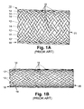
- a first subset of the flexible thread elements 12 have the same direction of winding and are displaced relative to each other about the cylindrical surface of the stent. They cross a second plurality of helical thread elements 14 which are also displaced relative to each other about the cylindrical surface of the stent, but having the opposite direction of winding. Accordingly, as shown in FIG. 1A , the threads 12 of the first subset cross the threads 14 of the second subset at crossing points 16 .
- the diameter reduces, as shown in FIG. 1 B.
- the wall of the stent is radially constricted so as to reduce the stent's diameter, the stent elongates. In other words, radial constriction and axial elongation go hand in hand. When the force is released, the stent tends to spring back to its resting diameter and length.
- Bioabsorbable stents also are known in the prior art. Bioabsorbable stents are manufactured from materials that dissolve over an extended period of time when exposed to bodily fluids and are absorbed into the surrounding cells of the body. Various bioabsorbable materials that are suitable for fabricating stents are known in the prior art, including polymers such as poly-L,D-lactic acid, poly-L-lactic acid, poly-D-lactic acid, polyglycolic acid, polylactic acid, polycaprolactone, polydioxanone, poly(lactic acid-ethylene oxide) copolymers, or combinations thereof. Vainionp et al., Prog Polym. Sci., vol. 14, pp. 697-716 (1989); U.S. Pat. No.
- stents need to be radially constricted, i.e., reduced in diameter, so that they can be inserted into the body lumen. Then, once they are in situ, the stent can be released and radially expanded.
- the delivery apparatus comprises an inner tube 5 surrounded by a concentric outer tube 1 .
- the outer tube is shorter than the inner tube so that the inner tube can extend from the outer tube at both ends.
- a handle 6 typically is provided at the proximal end of the inner tube.
- Another handle 2 is provided at the proximal end of the outer tube.
- the inner core is slidable within the outer tube by relative manipulation of the two handles.
- a stent 11 is loaded within the delivery apparatus captured between the inner and the outer tubes near the distal end of the delivery apparatus.
- the inner core may be hollow and adapted to accept a guide-wire 8 which, as is well known in the related arts, can be used to help guide the device to the stent delivery site in the body lumen 4 .
- a physician typically will make an incision in the body lumen 4 at a location remote from the stent desired deployment site and then guide the stent delivery device into the body lumen until the distal end of the stent delivery device is at the stent deployment site.
- the outer tube 1 is then withdrawn proximally while the inner tube 5 is held stationary. Accordingly, the outer tube 1 slides over the stent 11 , thus releasing it from radial constriction, whereby the stent radially expands and contacts the wall of the body lumen 4 .
- the stent 11 is held in place by the frictional force between the lumen wall and the stent body resulting from the radial expansion force of the stent.
- the stent is now fully deployed and the delivery device can be retracted and the procedure concluded.
- the invention is a method and apparatus for delivering a self expanding stent into a body lumen.
- the apparatus comprises an outer tube having a proximal end and a distal end and sized to hold a self-expanding stent therein in a radially constricted condition; an inner tube within the outer tube and having a proximal end and a distal end; a capturing element slidably mounted on the inner tube and including a foldable sleeve for assisting in radially constricting the stent and inserting it in the delivery apparatus between the two tubes; and a blocking element fixed to the inner tube near the distal end of the inner tube and adapted to pull the capturing element into the outer tube and block a stent inserted into the sleeve from being inserted into the capturing element past a predetermined point.
- the sleeve has a proximal end and a distal end, with the proximal end being smaller than the outer tube and the distal end being larger than the outer tube.
- the capturing element is carried on the inner tube such that the distal end of the sleeve can extend beyond the distal end of the outer tube in an unfolded condition and so that the sleeve can be drawn into and become folded within the outer tube when the inner tube is drawn proximally relative to the outer tube. Accordingly, a stent having an end inserted into the distal end of the sleeve can be drawn into the outer tube by drawing the inner tube proximally relative to the outer tube, thereby capturing the stent in a radially constricted condition within the outer tube.
- the stent is released by axially moving the outer tube proximally with respect to the inner tube.
- the capturing element is constructed so that it engages and is drawn along with the outer tube when the outer tube moves proximally with respect to the inner tube, thereby freeing the proximal extremity of the stent from the sleeve and allowing unimpeded stent release.
- the method is a method of loading a stent into a stent delivery apparatus such as described above comprising the steps of positioning the inner tube such that the distal end of the capturing element extends beyond the distal end of the outer tube; inserting an end of a stent into the sleeve; and drawing the inner tube proximally relative to the outer tube so as to draw the sleeve and the stent into the outer tube, thereby capturing the sleeve and the stent in the outer tube in a radially constricted condition.
- FIG. 1A is a plan view of a braided self expanding stent in accordance with the prior art.
- FIG. 1B is a plan view of the stent of FIG. 1A shown in a radially constricted/axially elongated state.
- FIG. 2 is a cross sectional view of a conventional stent and stent delivery device.
- FIG. 3 is a plan view of a stent and stent delivery device in accordance with the present invention.
- FIG. 4 is a cross sectional view of the stent and stent delivery device of FIG. 3 taken along line 4 — 4 in FIG. 3 .
- FIG. 5 is a detailed cross sectional view of the distal portion of the stent delivery device of FIG. 4 during the initial stage of inserting a self expanding stent into the stent delivery device.
- FIG. 6 is a detailed cross sectional view of the distal portion of the stent delivery device of FIG. 4 after the stent has been substantially or completely inserted into the stent delivery device.
- FIG. 7 is a detailed cross sectional view of a stent and stent delivery device after the stent has been released.
- FIG. 8 is a detailed cross sectional view of the capturing element and the distal portion of the delivery device in accordance with one particular embodiment of the invention.
- FIG. 9 is a detailed cross sectional view of the capturing element and the distal portion of the stent delivery device in accordance with another particular embodiment of the invention.
- Bioabsorbable self expanding stents while having substantial advantages in many respects over metal self expanding stents, also have potential drawbacks. For instance, when bioabsorbable self expanding stents are held in a radially constricted condition for a significant length of time, they tend to take a set and therefore do not fully expand to their original radial diameter when the radial constricting force is released. Even if they are able to expand to their original unrestricted diameter, they may have lower radial expansion force than before they were held in a radially constricted condition for a lengthy period.
- the cross sectional area of the space between inner tube 201 and outer tube 203 commonly is extremely small and only slightly greater than the thickness of the wall of the stent.
- the stent and the delivery apparatus can be quite small. Accordingly, it may be extremely difficult, if not impossible, for a physician to properly insert a stent into a stent delivery device by hand.
- the present invention aims to provide such a system.
- FIGS. 3 , 4 , 5 , and 6 The invention will first be described in connection with a first particular embodiment illustrated in FIGS. 3 , 4 , 5 , and 6 .
- FIGS. 3 and 4 are plan and cross sectional views, respectively, of the primary elements of a stent and stent delivery device in accordance with the present invention. It will be understood by those of skill in the art that certain components that are not particularly relevant to the present invention, such as handles, an optional guide wire, and a device tip are not shown for sake of clarity.
- the delivery device 200 has a proximal end 200 a and a distal end 200 b .
- the proximal end is the end that is held in the physician's hand during a medical procedure.
- the distal end is the end that is inserted into the lumen during a medical procedure.
- Device 200 comprises an inner tube 201 with a proximal end 201 a and a distal end 201 b and an outer tube 203 with a proximal end 203 a and a distal end 203 b .
- a stent 205 is to be inserted into the delivery device 200 so as to be captured in a radially constricted condition between outer tube 203 and inner tube 201 .
- Capturing element 206 shown in detail in FIG. 5 , is provided in order to facilitate easy insertion of the stent into the stent delivery device and protect the proximal extremity of the stent during its insertion in the delivery apparatus by preventing the stent threads from unraveling or bending.
- Capturing element 206 includes a carriage 211 that may be in the form of a band or ring that surrounds the inner tube 201 and fits within the space between inner tube 201 and outer tube 203 and is slidable longitudinally on the inner tube 201 . Attached at the distal end of carriage 211 is a conical or funnel-shaped sleeve 207 .
- the proximal end 207 a of the sleeve 207 is fixedly attached to the distal end of carriage 211 , such as by adhesive.
- Sleeve 207 is not rigid, but is foldable such that, when the capturing element 206 is drawn into outer tube 203 , sleeve 207 collapses and folds in on itself to fit within outer tube 203 .
- Sleeve 207 may be formed of a thin biocompatible plastic such as polyethylene terepthalate (PET), nylon, polytetraflorethylene (PTFE) or other suitable materials or material combinations.
- the inside and outside surfaces of the sleeve 207 may have different properties in order to facilitate the grasping of the stent inside the sleeve and the withdrawal of the sleeve into the outer tube of the delivery apparatus. Accordingly, the inner surface of the sleeve may consist of a material or coating having a high coefficient of friction or a rough surface, whereas the outer part of the sleeve may consist of a material having a low coefficient of friction or a slippery coating such as may be achieved with processes like siliconization or hydrogel coating.
- the inside surface of the sleeve may be coated with hydrogel coating that is activated by flushing the device with saline once the stent has been fully loaded in the delivery apparatus, therefore, facilitating the release of the stent from the sleeve at the initiation of stent release.
- the distal end 207 b of sleeve 207 is open and, in fact, comprises an opening larger than the opening at the distal tip of outer tube 203 .
- the opening at distal end 207 b of the sleeve 207 may, but need not, be as large as or larger than the radial diameter of the radially unconstrained stent. In a preferred embodiment, the opening is smaller than the unconstrained diameter of the stent.
- the opening should be large enough to allow a physician to insert one end of the stent into the sleeve 207 by radially constricting the stent by hand or other implement without too much difficulty.
- an end of the stent is within sleeve 207 , it can continue to be pushed into the sleeve 207 (i.e., toward the proximal end of the delivery device) and the inner walls of the sleeve 207 will thereby further radially constrict the end of the stent until the end is constricted to the diameter of the proximal end 207 a of the sleeve, which is smaller than the inner diameter of the outer tube 203 .
- the stent will enter the outer tube and be captured within the delivery apparatus in a radially constricted condition between outer tube 203 and inner tube 201 .
- a separate blocking ring 209 may be fixedly attached to the inner tube 201 distally of the carriage 211 .
- separate blocking ring 209 may be formed integrally with the inner tube 201 .
- Separate blocking ring 209 has two primary functions. First, it blocks the end of the stent from being inserted into the delivery device 200 proximally of the blocking ring 209 (and thus proximally of the capturing element 206 ). It might be possible for the stent to slip into the gap between the inner tube 201 and the carriage 211 of the capturing element 206 . Blocking ring 209 prevents this. Further, blocking ring 209 prevents the capturing element from falling off of the end of the inner tube.
- the inner tube 201 will be drawn proximally relative to the outer tube 203 during insertion of stent 205 into the delivery device 200 .
- blocking ring 209 will contact carriage 211 of capturing element 206 and draw it proximally along with it. Otherwise, the capturing element 206 would simply fall off of the distal end of the inner tube 201 when the inner tube is drawn proximally into the outer tube 203 . Accordingly, blocking ring 209 prevents the capturing element 206 from becoming situated distally of a predetermined point relative to said inner tube.
- FIG. 6 shows the distal end of the delivery device 200 with the stent 205 and capturing element 206 have been inserted into the delivery device 200 .
- FIG. 7 illustrates the condition of the stent and stent delivery device after deployment of the stent.
- the blocking ring 209 prevents any proximal motion of the stent relative to the inner tube when the outer tube is withdrawn proximally to release the stent, thereby allowing full stent release when the distal end of the outer tube is withdrawn proximally to the blocking ring.
- FIGS. 8 and 9 illustrate alternative embodiments of the capturing element carriage 211 adapted to help assure the capturing element 206 is drawn along with the outer tube when the outer tube is drawn proximally to release the stent.
- FIG. 8 illustrates an embodiment in which carriage 211 includes distally angled barbs 801 that engage the inner surface of the outer tube 203 and resist distal motion of the capturing element 206 relative to the outer tube but allow proximal motion.
- FIG. 9 shows an alternative embodiment in which, instead of barbs, one or more leaf springs 901 are positioned on the outer surface of the carriage 211 directed obliquely distally to resist distal motion of the carriage 211 relative to the outer tube 203 , but allow proximal motion of the carriage relative to the outer tube.
- the sleeve 207 may be made of any suitable polymer, elastomer, or metal. It may be porous, perforated or slotted to allow fluid to flow in the space between said inner tube and said outer tube.
- the inner tube 201 extends beyond the capturing element such that the stent is captured between the inner tube and the outer tube. However, this is not necessary.
- the blocking element 209 may be attached at the very distal tip of the inner tube 201 such that the stent, when inserted, is captured is within outer tube 203 and there is no inner tube adjacent the stent.
- the inner tube 201 may be solid or hollow. If hollow, a guide-wire may or may not be used to help guide the delivery apparatus to the stent deployment site.
- the components of the capturing element can have material properties that alter in body temperature or in the presence of bodily fluids.
- the carriage 211 of the capturing element 206 may be formed of a material that expands when subjected to body temperature or bodily fluids, thus ensuring a sufficiently strong frictional engagement between the inner surface of the outer tube 203 and the carriage 211 to cause it to be carried along with the outer tube 203 when the outer tube is drawn proximally.
- the carriage 211 and the blocking ring 209 as solid annuluses, this is not necessary. Neither element need be circular nor solid.
- sleeve 207 Longitudinal grooves or holes may be machined in the carriage 211 to allow fluid to flow in the space between the inner tube and the outer tube, for instance, for flushing the catheter prior to use or for the injection of contrast media during the procedure
- the invention has hereinabove been described in connection with a standard type of self-expanding stent, it is equally applicable to other forms of stents and, in fact, any tubular self-expanding prosthesis that is delivered in the same general manner.
- the invention is equally applicable to stent-grafts and covered stents, both of which are stent-based medical prostheses that are well known to those of skill in the related arts. In fact, it is not even necessary that the prosthesis be self expanding.
- the invention can be useful in connection with any prosthesis that must be inserted into a small opening.
Landscapes
- Health & Medical Sciences (AREA)
- Engineering & Computer Science (AREA)
- Biomedical Technology (AREA)
- Cardiology (AREA)
- Oral & Maxillofacial Surgery (AREA)
- Transplantation (AREA)
- Heart & Thoracic Surgery (AREA)
- Vascular Medicine (AREA)
- Life Sciences & Earth Sciences (AREA)
- Animal Behavior & Ethology (AREA)
- General Health & Medical Sciences (AREA)
- Public Health (AREA)
- Veterinary Medicine (AREA)
- Media Introduction/Drainage Providing Device (AREA)
- Prostheses (AREA)
Priority Applications (6)
| Application Number | Priority Date | Filing Date | Title |
|---|---|---|---|
| US10/025,669 US6902575B2 (en) | 2001-12-18 | 2001-12-18 | Stent delivery apparatus and method |
| JP2003552172A JP2005512634A (ja) | 2001-12-18 | 2002-12-18 | ステントを搬送するための装置及び方法 |
| AU2002366382A AU2002366382B2 (en) | 2001-12-18 | 2002-12-18 | Stent delivery apparatus and method |
| PCT/US2002/040673 WO2003051235A1 (en) | 2001-12-18 | 2002-12-18 | Stent delivery apparatus and method |
| CA002470433A CA2470433A1 (en) | 2001-12-18 | 2002-12-18 | Stent delivery apparatus and method |
| EP02805214A EP1463460A1 (en) | 2001-12-18 | 2002-12-18 | Stent delivery apparatus and method |
Applications Claiming Priority (1)
| Application Number | Priority Date | Filing Date | Title |
|---|---|---|---|
| US10/025,669 US6902575B2 (en) | 2001-12-18 | 2001-12-18 | Stent delivery apparatus and method |
Publications (2)
| Publication Number | Publication Date |
|---|---|
| US20030114910A1 US20030114910A1 (en) | 2003-06-19 |
| US6902575B2 true US6902575B2 (en) | 2005-06-07 |
Family
ID=21827402
Family Applications (1)
| Application Number | Title | Priority Date | Filing Date |
|---|---|---|---|
| US10/025,669 Expired - Fee Related US6902575B2 (en) | 2001-12-18 | 2001-12-18 | Stent delivery apparatus and method |
Country Status (6)
| Country | Link |
|---|---|
| US (1) | US6902575B2 (enExample) |
| EP (1) | EP1463460A1 (enExample) |
| JP (1) | JP2005512634A (enExample) |
| AU (1) | AU2002366382B2 (enExample) |
| CA (1) | CA2470433A1 (enExample) |
| WO (1) | WO2003051235A1 (enExample) |
Cited By (22)
| Publication number | Priority date | Publication date | Assignee | Title |
|---|---|---|---|---|
| US20040049222A1 (en) * | 2002-06-28 | 2004-03-11 | Schaeffer Darin G. | Introducer sheath |
| US20050154443A1 (en) * | 2004-01-09 | 2005-07-14 | Rubicon Medical, Inc. | Stent delivery device |
| US20070043381A1 (en) * | 2005-08-19 | 2007-02-22 | Icon Medical Corp. | Medical device deployment instrument |
| US20070270932A1 (en) * | 2006-05-19 | 2007-11-22 | Boston Scientific Scimed, Inc. | Apparatus and method for loading and delivering a stent |
| US20080058858A1 (en) * | 2006-08-30 | 2008-03-06 | Smith David W | Method of imparting a mono-axial or multiaxial stiffness to extruded materials and products resulting therefrom |
| US20080142005A1 (en) * | 2005-05-10 | 2008-06-19 | Ralf Schnell | Insertion Aid for Percutaneous Tracheostomy |
| US20080183272A1 (en) * | 2007-01-25 | 2008-07-31 | Boston Scientific Scimed, Inc. | Endoscope with preloaded or preloadable stent |
| US20100049297A1 (en) * | 2008-08-21 | 2010-02-25 | C.R. Bard, Inc. | Method of loading a stent into a sheath |
| US20100057185A1 (en) * | 2008-09-04 | 2010-03-04 | Cook Incorporated | Sliding Split-Sleeve Implant Compressor |
| US20110054517A1 (en) * | 2006-10-23 | 2011-03-03 | Glaxosmithkline Llc | External nasal dilator and methods of manufacture |
| US20110060397A1 (en) * | 2008-05-09 | 2011-03-10 | C.R. Bard, Inc. | Method of loading a stent into a sheath |
| US8088060B2 (en) | 2000-03-15 | 2012-01-03 | Orbusneich Medical, Inc. | Progenitor endothelial cell capturing with a drug eluting implantable medical device |
| US20120283765A1 (en) * | 2005-05-25 | 2012-11-08 | Tyco Healthcare Group Lp | System and method for delivering and deploying an occluding device within a vessel |
| US20130035749A1 (en) * | 2011-08-02 | 2013-02-07 | Cook Medical Technologies Llc | Delivery device having a variable diameter introducer sheath |
| US8992605B2 (en) | 2004-09-14 | 2015-03-31 | Edwards Lifesciences Ag | Device and method for reducing mitral valve regurgitation |
| US9522217B2 (en) | 2000-03-15 | 2016-12-20 | Orbusneich Medical, Inc. | Medical device with coating for capturing genetically-altered cells and methods for using same |
| US9622895B2 (en) | 2013-10-15 | 2017-04-18 | Boston Scientific Scimed, Inc. | Methods and systems for loading and delivering a stent |
| US10028854B2 (en) | 2012-02-02 | 2018-07-24 | Covidien Lp | Stent retaining systems |
| US20180235743A1 (en) * | 2017-02-23 | 2018-08-23 | Boston Scientific Scimed, Inc. | Medical drain device |
| US10660776B2 (en) | 2016-04-11 | 2020-05-26 | Boston Scientific Scimed, Inc. | Stent delivery system with collapsible loading frame |
| US10881542B2 (en) | 2016-04-05 | 2021-01-05 | Boston Scientific Scimed, Inc. | Stent delivery device |
| US11471311B2 (en) | 2018-04-09 | 2022-10-18 | Boston Scientific Scimed, Inc. | Stent delivery system with reduced deployment force |
Families Citing this family (39)
| Publication number | Priority date | Publication date | Assignee | Title |
|---|---|---|---|---|
| US8292943B2 (en) | 2003-09-03 | 2012-10-23 | Bolton Medical, Inc. | Stent graft with longitudinal support member |
| US11259945B2 (en) | 2003-09-03 | 2022-03-01 | Bolton Medical, Inc. | Dual capture device for stent graft delivery system and method for capturing a stent graft |
| US11596537B2 (en) | 2003-09-03 | 2023-03-07 | Bolton Medical, Inc. | Delivery system and method for self-centering a proximal end of a stent graft |
| US20080264102A1 (en) | 2004-02-23 | 2008-10-30 | Bolton Medical, Inc. | Sheath Capture Device for Stent Graft Delivery System and Method for Operating Same |
| US8500792B2 (en) | 2003-09-03 | 2013-08-06 | Bolton Medical, Inc. | Dual capture device for stent graft delivery system and method for capturing a stent graft |
| US20070198078A1 (en) | 2003-09-03 | 2007-08-23 | Bolton Medical, Inc. | Delivery system and method for self-centering a Proximal end of a stent graft |
| US7763063B2 (en) | 2003-09-03 | 2010-07-27 | Bolton Medical, Inc. | Self-aligning stent graft delivery system, kit, and method |
| US9198786B2 (en) | 2003-09-03 | 2015-12-01 | Bolton Medical, Inc. | Lumen repair device with capture structure |
| US7918880B2 (en) * | 2005-02-16 | 2011-04-05 | Boston Scientific Scimed, Inc. | Self-expanding stent and delivery system |
| US20090192518A1 (en) * | 2008-01-24 | 2009-07-30 | Boston Scientific Scimed, Inc. | Apparatus and method for loading and delivering a stent having improved handles to control relative catheter component movement |
| US20100042202A1 (en) * | 2008-08-13 | 2010-02-18 | Kamal Ramzipoor | Composite stent having multi-axial flexibility |
| EP3219292B1 (en) | 2008-06-30 | 2019-08-14 | Bolton Medical Inc. | Abdominal aortic aneurysms systems |
| EP2405868B1 (en) | 2009-03-13 | 2017-06-28 | Bolton Medical Inc. | System for deploying an endoluminal prosthesis at a surgical site |
| WO2011022658A1 (en) | 2009-08-20 | 2011-02-24 | Cook Incorporated | Loading apparatus and system for expandable intraluminal medical devices |
| US8900286B2 (en) * | 2010-03-01 | 2014-12-02 | Abbott Cardiovascular Systems, Inc. | Medical device shield and methods for delivering a medical device |
| US9320597B2 (en) * | 2010-03-30 | 2016-04-26 | Medtronic, Inc. | Transcatheter prosthetic heart valve delivery system with recapturing feature and method |
| US8979824B2 (en) | 2010-06-21 | 2015-03-17 | Boston Scientific Scimed, Inc. | Stent delivery system having retention structure |
| US8808348B2 (en) * | 2010-06-23 | 2014-08-19 | Boston Scientific Scimed, Inc. | Delivery system having stent retention structure |
| WO2012092143A1 (en) * | 2010-12-30 | 2012-07-05 | Boston Scientific Scimed, Inc. | Loading basket for a stent delivery system |
| WO2012114780A1 (ja) * | 2011-02-24 | 2012-08-30 | テルモ株式会社 | ステントデリバリーシステム |
| PL2529701T3 (pl) * | 2011-06-01 | 2014-04-30 | Nvt Ag | Układ do instalowania protezy zastawki serca |
| US9480558B2 (en) | 2011-12-05 | 2016-11-01 | Medtronic, Inc. | Transcatheter valve having reduced seam exposure |
| WO2013154749A1 (en) | 2012-04-12 | 2013-10-17 | Bolton Medical, Inc. | Vascular prosthetic delivery device and method of use |
| US10172734B2 (en) | 2013-03-13 | 2019-01-08 | DePuy Synthes Products, Inc. | Capture tube mechanism for delivering and releasing a stent |
| US9439751B2 (en) | 2013-03-15 | 2016-09-13 | Bolton Medical, Inc. | Hemostasis valve and delivery systems |
| US10149758B2 (en) | 2014-04-01 | 2018-12-11 | Medtronic, Inc. | System and method of stepped deployment of prosthetic heart valve |
| US10583022B2 (en) | 2014-11-19 | 2020-03-10 | Boston Scientific Scimed, Inc. | Stent delivery systems with a reconstraining member |
| CN113384384A (zh) | 2015-06-29 | 2021-09-14 | 莱拉医药公司 | 支架装载和递送系统 |
| WO2017152097A1 (en) | 2016-03-03 | 2017-09-08 | Medtronic Vascular Inc. | Stented prosthesis delivery system having a bumper |
| US11426276B2 (en) * | 2016-10-12 | 2022-08-30 | Medtronic Vascular, Inc. | Stented prosthetic heart valve delivery system having an expandable bumper |
| CN107874881B (zh) * | 2017-12-27 | 2024-08-02 | 江苏启灏医疗科技有限公司 | 一种宫腔支架输送组件 |
| AU2019298316B2 (en) | 2018-07-06 | 2022-09-29 | Cook Medical Technologies Llc | Storage devices, loading devices, delivery systems kits, and associated methods |
| CN110960341A (zh) * | 2018-09-29 | 2020-04-07 | 上海心瑞医疗科技有限公司 | 一种支架输送系统 |
| US11690743B2 (en) | 2019-02-15 | 2023-07-04 | Boston Scientific Scimed, Inc. | Stent delivery system |
| US11504254B2 (en) * | 2020-03-05 | 2022-11-22 | Fluid Biomed Inc. | System and methods for compressing endovascular devices |
| WO2021262264A1 (en) | 2020-06-24 | 2021-12-30 | Bolton Medical, Inc. | Anti-backspin component for vascular prosthesis delivery device |
| CN112891021B (zh) * | 2020-12-31 | 2024-05-10 | 先健科技(深圳)有限公司 | 管腔装置及输送器 |
| CN115919521A (zh) * | 2022-12-07 | 2023-04-07 | 江苏博朗森思医疗器械有限公司 | 肠道防吸收器的取出装置 |
| CN116616960B (zh) * | 2023-06-01 | 2025-05-23 | 佰仁医疗(江苏)有限公司 | 心脏瓣膜输送器 |
Citations (7)
| Publication number | Priority date | Publication date | Assignee | Title |
|---|---|---|---|---|
| US4655771A (en) | 1982-04-30 | 1987-04-07 | Shepherd Patents S.A. | Prosthesis comprising an expansible or contractile tubular body |
| US5026377A (en) | 1989-07-13 | 1991-06-25 | American Medical Systems, Inc. | Stent placement instrument and method |
| US5683451A (en) | 1994-06-08 | 1997-11-04 | Cardiovascular Concepts, Inc. | Apparatus and methods for deployment release of intraluminal prostheses |
| US6306163B1 (en) * | 1998-08-04 | 2001-10-23 | Advanced Cardiovascular Systems, Inc. | Assembly for collecting emboli and method of use |
| US6391050B1 (en) * | 2000-02-29 | 2002-05-21 | Scimed Life Systems, Inc. | Self-expanding stent delivery system |
| US6514280B1 (en) | 1998-04-02 | 2003-02-04 | Salviac Limited | Delivery catheter |
| US6602280B2 (en) * | 2000-02-02 | 2003-08-05 | Trivascular, Inc. | Delivery system and method for expandable intracorporeal device |
-
2001
- 2001-12-18 US US10/025,669 patent/US6902575B2/en not_active Expired - Fee Related
-
2002
- 2002-12-18 WO PCT/US2002/040673 patent/WO2003051235A1/en not_active Ceased
- 2002-12-18 JP JP2003552172A patent/JP2005512634A/ja active Pending
- 2002-12-18 CA CA002470433A patent/CA2470433A1/en not_active Abandoned
- 2002-12-18 EP EP02805214A patent/EP1463460A1/en not_active Withdrawn
- 2002-12-18 AU AU2002366382A patent/AU2002366382B2/en not_active Ceased
Patent Citations (8)
| Publication number | Priority date | Publication date | Assignee | Title |
|---|---|---|---|---|
| US4655771A (en) | 1982-04-30 | 1987-04-07 | Shepherd Patents S.A. | Prosthesis comprising an expansible or contractile tubular body |
| US4655771B1 (en) | 1982-04-30 | 1996-09-10 | Medinvent Ams Sa | Prosthesis comprising an expansible or contractile tubular body |
| US5026377A (en) | 1989-07-13 | 1991-06-25 | American Medical Systems, Inc. | Stent placement instrument and method |
| US5683451A (en) | 1994-06-08 | 1997-11-04 | Cardiovascular Concepts, Inc. | Apparatus and methods for deployment release of intraluminal prostheses |
| US6514280B1 (en) | 1998-04-02 | 2003-02-04 | Salviac Limited | Delivery catheter |
| US6306163B1 (en) * | 1998-08-04 | 2001-10-23 | Advanced Cardiovascular Systems, Inc. | Assembly for collecting emboli and method of use |
| US6602280B2 (en) * | 2000-02-02 | 2003-08-05 | Trivascular, Inc. | Delivery system and method for expandable intracorporeal device |
| US6391050B1 (en) * | 2000-02-29 | 2002-05-21 | Scimed Life Systems, Inc. | Self-expanding stent delivery system |
Cited By (44)
| Publication number | Priority date | Publication date | Assignee | Title |
|---|---|---|---|---|
| US8088060B2 (en) | 2000-03-15 | 2012-01-03 | Orbusneich Medical, Inc. | Progenitor endothelial cell capturing with a drug eluting implantable medical device |
| US9522217B2 (en) | 2000-03-15 | 2016-12-20 | Orbusneich Medical, Inc. | Medical device with coating for capturing genetically-altered cells and methods for using same |
| US20040049222A1 (en) * | 2002-06-28 | 2004-03-11 | Schaeffer Darin G. | Introducer sheath |
| US7534250B2 (en) * | 2002-06-28 | 2009-05-19 | Cook Critical Care | Introducer sheath |
| US9254213B2 (en) | 2004-01-09 | 2016-02-09 | Rubicon Medical, Inc. | Stent delivery device |
| US20050154443A1 (en) * | 2004-01-09 | 2005-07-14 | Rubicon Medical, Inc. | Stent delivery device |
| US12458497B2 (en) | 2004-09-14 | 2025-11-04 | Edwards Lifesciences Ag | Method of implanting valve prosthesis having atrial anchoring |
| US8992605B2 (en) | 2004-09-14 | 2015-03-31 | Edwards Lifesciences Ag | Device and method for reducing mitral valve regurgitation |
| US20080142005A1 (en) * | 2005-05-10 | 2008-06-19 | Ralf Schnell | Insertion Aid for Percutaneous Tracheostomy |
| US8251068B2 (en) * | 2005-05-10 | 2012-08-28 | Tracoe Medical Gmbh | Insertion aid for percutaneous tracheostomy |
| US10064747B2 (en) * | 2005-05-25 | 2018-09-04 | Covidien Lp | System and method for delivering and deploying an occluding device within a vessel |
| US20120283765A1 (en) * | 2005-05-25 | 2012-11-08 | Tyco Healthcare Group Lp | System and method for delivering and deploying an occluding device within a vessel |
| US20070043381A1 (en) * | 2005-08-19 | 2007-02-22 | Icon Medical Corp. | Medical device deployment instrument |
| US9943429B2 (en) * | 2006-05-19 | 2018-04-17 | Boston Scientific Scimed, Inc. | Apparatus for loading and delivering a stent |
| US20150081005A1 (en) * | 2006-05-19 | 2015-03-19 | Boston Scientific Scimed, Inc. | Apparatus for Loading and Delivering a Stent |
| EP2018138B1 (en) * | 2006-05-19 | 2015-07-08 | Boston Scientific Limited | Apparatus and method for loading and delivering a stent |
| US20070270932A1 (en) * | 2006-05-19 | 2007-11-22 | Boston Scientific Scimed, Inc. | Apparatus and method for loading and delivering a stent |
| US10925761B2 (en) * | 2006-05-19 | 2021-02-23 | Boston Scientific Scimed, Inc. | Apparatus for loading and delivering a stent |
| US8535368B2 (en) * | 2006-05-19 | 2013-09-17 | Boston Scientific Scimed, Inc. | Apparatus for loading and delivering a stent |
| US8858614B2 (en) | 2006-05-19 | 2014-10-14 | Boston Scientific Scimed, Inc. | Apparatus for loading and delivering a stent |
| US8834514B2 (en) | 2006-08-30 | 2014-09-16 | Xennovate Medical Llc | Resilient band medical device |
| US20080058858A1 (en) * | 2006-08-30 | 2008-03-06 | Smith David W | Method of imparting a mono-axial or multiaxial stiffness to extruded materials and products resulting therefrom |
| USD662203S1 (en) | 2006-08-30 | 2012-06-19 | Smithkline Beecham Corporation | Nasal dilator |
| US8834511B2 (en) | 2006-10-23 | 2014-09-16 | GlaxoSmithKline, LLC | External nasal dilator and methods of manufacture |
| US20110054517A1 (en) * | 2006-10-23 | 2011-03-03 | Glaxosmithkline Llc | External nasal dilator and methods of manufacture |
| US9901479B2 (en) | 2006-10-23 | 2018-02-27 | GlaxoSmithKline, LLC | External nasal dilator and methods |
| US9125761B2 (en) * | 2007-01-25 | 2015-09-08 | Boston Scientific Scimed, Inc. | Endoscope with preloaded or preloadable stent |
| US20080183272A1 (en) * | 2007-01-25 | 2008-07-31 | Boston Scientific Scimed, Inc. | Endoscope with preloaded or preloadable stent |
| US9687370B2 (en) * | 2008-05-09 | 2017-06-27 | C.R. Bard, Inc. | Method of loading a stent into a sheath |
| US20110060397A1 (en) * | 2008-05-09 | 2011-03-10 | C.R. Bard, Inc. | Method of loading a stent into a sheath |
| US20100049297A1 (en) * | 2008-08-21 | 2010-02-25 | C.R. Bard, Inc. | Method of loading a stent into a sheath |
| US9833349B2 (en) * | 2008-08-21 | 2017-12-05 | C. R. Bard, Inc. | Method of loading a stent into a sheath |
| US8359721B2 (en) * | 2008-09-04 | 2013-01-29 | Cook Medical Technologies Llc | Sliding split-sleeve implant compressor |
| US20100057185A1 (en) * | 2008-09-04 | 2010-03-04 | Cook Incorporated | Sliding Split-Sleeve Implant Compressor |
| US9241818B2 (en) * | 2011-08-02 | 2016-01-26 | Cook Medical Technologies Llc | Delivery device having a variable diameter introducer sheath |
| US20130035749A1 (en) * | 2011-08-02 | 2013-02-07 | Cook Medical Technologies Llc | Delivery device having a variable diameter introducer sheath |
| US11083608B2 (en) | 2012-02-02 | 2021-08-10 | Covidien Lp | Stent retaining systems |
| US10028854B2 (en) | 2012-02-02 | 2018-07-24 | Covidien Lp | Stent retaining systems |
| US9622895B2 (en) | 2013-10-15 | 2017-04-18 | Boston Scientific Scimed, Inc. | Methods and systems for loading and delivering a stent |
| US10881542B2 (en) | 2016-04-05 | 2021-01-05 | Boston Scientific Scimed, Inc. | Stent delivery device |
| US10660776B2 (en) | 2016-04-11 | 2020-05-26 | Boston Scientific Scimed, Inc. | Stent delivery system with collapsible loading frame |
| US20180235743A1 (en) * | 2017-02-23 | 2018-08-23 | Boston Scientific Scimed, Inc. | Medical drain device |
| US11744692B2 (en) * | 2017-02-23 | 2023-09-05 | Boston Scientific Scimed, Inc. | Medical drain device |
| US11471311B2 (en) | 2018-04-09 | 2022-10-18 | Boston Scientific Scimed, Inc. | Stent delivery system with reduced deployment force |
Also Published As
| Publication number | Publication date |
|---|---|
| WO2003051235A1 (en) | 2003-06-26 |
| AU2002366382B2 (en) | 2007-07-05 |
| EP1463460A1 (en) | 2004-10-06 |
| CA2470433A1 (en) | 2003-06-26 |
| AU2002366382A1 (en) | 2003-06-30 |
| US20030114910A1 (en) | 2003-06-19 |
| JP2005512634A (ja) | 2005-05-12 |
Similar Documents
| Publication | Publication Date | Title |
|---|---|---|
| US6902575B2 (en) | Stent delivery apparatus and method | |
| US6991646B2 (en) | Method and apparatus for delivering a stent into a body lumen | |
| EP0952795B1 (en) | Splittable sleeve, stent deployment device | |
| JP4574131B2 (ja) | 拡張可能なステント及び送達システム | |
| JP5313490B2 (ja) | 固定ピンを有するステント移植片 | |
| US6264671B1 (en) | Stent delivery catheter and method of use | |
| US7172620B2 (en) | Delivery catheter | |
| JP2004517648A (ja) | 向上した放射方向の拡張性並びに形状記憶性を有する自己拡張型ステント | |
| US20110218608A1 (en) | Vascular Prosthesis Delivery System and Method | |
| EP1813223B1 (en) | Stent delivery system to improve placement accuracy for self-expanding stent | |
| CA2599441C (en) | Removable coiled stent | |
| JP2005533557A (ja) | 管腔内拡張システム | |
| JP2004267750A (ja) | 拡張可能なステント及びデリバリーシステム、方法 | |
| JP2010535066A (ja) | 2段階引き出しのデバイスデリバリーシステム | |
| AU4270700A (en) | Stent keeper for a self-expanding stent delivery system | |
| WO1991007928A1 (en) | Angioplasty stent for use with a catheter |
Legal Events
| Date | Code | Title | Description |
|---|---|---|---|
| AS | Assignment |
Owner name: BIONX IMPLANTS, INC., PENNSYLVANIA Free format text: ASSIGNMENT OF ASSIGNORS INTEREST;ASSIGNORS:CLERC, CLAUDE O.;NUUTINEN, JUHA-PEKKA;LAAKSO, KARI AARNE JUHANI;REEL/FRAME:012406/0966;SIGNING DATES FROM 20011211 TO 20011214 |
|
| FPAY | Fee payment |
Year of fee payment: 4 |
|
| FEPP | Fee payment procedure |
Free format text: PAYOR NUMBER ASSIGNED (ORIGINAL EVENT CODE: ASPN); ENTITY STATUS OF PATENT OWNER: LARGE ENTITY |
|
| FPAY | Fee payment |
Year of fee payment: 8 |
|
| REMI | Maintenance fee reminder mailed | ||
| LAPS | Lapse for failure to pay maintenance fees | ||
| STCH | Information on status: patent discontinuation |
Free format text: PATENT EXPIRED DUE TO NONPAYMENT OF MAINTENANCE FEES UNDER 37 CFR 1.362 |
|
| FP | Lapsed due to failure to pay maintenance fee |
Effective date: 20170607 |