US6879232B2 - Wide ratio autotransformer-type current ranging - Google Patents
Wide ratio autotransformer-type current ranging Download PDFInfo
- Publication number
- US6879232B2 US6879232B2 US10/380,397 US38039703A US6879232B2 US 6879232 B2 US6879232 B2 US 6879232B2 US 38039703 A US38039703 A US 38039703A US 6879232 B2 US6879232 B2 US 6879232B2
- Authority
- US
- United States
- Prior art keywords
- winding
- terminals
- taps
- current
- coupled
- Prior art date
- Legal status (The legal status is an assumption and is not a legal conclusion. Google has not performed a legal analysis and makes no representation as to the accuracy of the status listed.)
- Expired - Lifetime, expires
Links
Images


Classifications
-
- H—ELECTRICITY
- H02—GENERATION; CONVERSION OR DISTRIBUTION OF ELECTRIC POWER
- H02P—CONTROL OR REGULATION OF ELECTRIC MOTORS, ELECTRIC GENERATORS OR DYNAMO-ELECTRIC CONVERTERS; CONTROLLING TRANSFORMERS, REACTORS OR CHOKE COILS
- H02P13/00—Arrangements for controlling transformers, reactors or choke coils, for the purpose of obtaining a desired output
- H02P13/06—Arrangements for controlling transformers, reactors or choke coils, for the purpose of obtaining a desired output by tap-changing; by rearranging interconnections of windings
-
- G—PHYSICS
- G05—CONTROLLING; REGULATING
- G05F—SYSTEMS FOR REGULATING ELECTRIC OR MAGNETIC VARIABLES
- G05F1/00—Automatic systems in which deviations of an electric quantity from one or more predetermined values are detected at the output of the system and fed back to a device within the system to restore the detected quantity to its predetermined value or values, i.e. retroactive systems
- G05F1/10—Regulating voltage or current
- G05F1/12—Regulating voltage or current wherein the variable actually regulated by the final control device is ac
- G05F1/14—Regulating voltage or current wherein the variable actually regulated by the final control device is ac using tap transformers or tap changing inductors as final control devices
-
- H—ELECTRICITY
- H01—ELECTRIC ELEMENTS
- H01F—MAGNETS; INDUCTANCES; TRANSFORMERS; SELECTION OF MATERIALS FOR THEIR MAGNETIC PROPERTIES
- H01F38/00—Adaptations of transformers or inductances for specific applications or functions
- H01F38/20—Instruments transformers
- H01F38/22—Instruments transformers for single phase ac
- H01F38/28—Current transformers
- H01F38/32—Circuit arrangements
-
- G—PHYSICS
- G01—MEASURING; TESTING
- G01R—MEASURING ELECTRIC VARIABLES; MEASURING MAGNETIC VARIABLES
- G01R15/00—Details of measuring arrangements of the types provided for in groups G01R17/00 - G01R29/00, G01R33/00 - G01R33/26 or G01R35/00
- G01R15/14—Adaptations providing voltage or current isolation, e.g. for high-voltage or high-current networks
- G01R15/18—Adaptations providing voltage or current isolation, e.g. for high-voltage or high-current networks using inductive devices, e.g. transformers
- G01R15/183—Adaptations providing voltage or current isolation, e.g. for high-voltage or high-current networks using inductive devices, e.g. transformers using transformers with a magnetic core
-
- H—ELECTRICITY
- H01—ELECTRIC ELEMENTS
- H01F—MAGNETS; INDUCTANCES; TRANSFORMERS; SELECTION OF MATERIALS FOR THEIR MAGNETIC PROPERTIES
- H01F29/00—Variable transformers or inductances not covered by group H01F21/00
- H01F29/02—Variable transformers or inductances not covered by group H01F21/00 with tappings on coil or winding; with provision for rearrangement or interconnection of windings
Definitions
- This invention relates to transformers. It is disclosed in the context of a precision current transformer, or current ranging transformer. However, it is believed to be useful in other applications as well.
- Current transformers are used to multiply or divide currents precisely for measurement or calibration.
- Current rangers are current transformer which have multiple taps on their windings to provide multiple turns ratios in a single device.
- Current rangers usually include two electrically isolated, magnetically coupled windings, typically referred to as a primary winding and a secondary winding. Either or both of these winding may have multiple taps.
- a transformer circuit includes a winding having a pair of terminals and taps by which electrical contact can be made to the winding at locations between the terminals along its length.
- a first switch permits contact to be made selectively to a selected one of the taps.
- a second switch permits contact to be made selectively to a selected one of the taps.
- An amplifier has an inverting ( ⁇ ) input terminal, a non-inverting (+) input terminal and an output terminal. The + and ⁇ input terminals are coupled across the pair of terminals of the winding.
- the output terminal of the amplifier is coupled to one of the first and second switches so that selectively making contact with one of the taps couples the selected tap to the output terminal of the amplifier.
- the taps are spaced integral numbers of coils of the winding apart along the winding, thereby permitting integral ratios of coils to be selected by selective actuation of the first switch and the second switch.
- the taps are so spaced along the winding that integral ratios of coils are selected by selective actuation of the first switch and the second switch.
- a transformer circuit includes a winding having a pair of terminals and taps by which electrical contact can be made to the winding at locations between the terminals along its length.
- the circuit further includes a switch for selectively making contact to a selected one of the taps, and an amplifier having ⁇ and + input terminals and an output terminal.
- One of the + and ⁇ input terminals is coupled to one of the terminals of the winding.
- the other of the + and ⁇ input terminals is coupled to the output terminal of the amplifier.
- the + terminal of the amplifier is coupled to the said one of the terminals of the winding and the ⁇ input terminal is coupled to the output terminal of the amplifier.
- the taps are spaced integral numbers of coils of the winding apart along the winding, thereby permitting integral ratios of coils to be selected by selective actuation of the switch.
- the taps are so spaced along the winding that integral ratios of coils are selected by selective actuation of the switch.
- the apparatus further includes a source. Selective actuation of the switch selectively couples the source to said one of the taps.
- the apparatus further includes two, two-terminal power supplies. Opposite polarity terminals of the two power supplies are joined. The remaining two terminals of the two power supplies being coupled to the amplifier to provide operating potential to it.
- the apparatus includes a load.
- One terminal of the load is coupled to the joined terminals of the power supplies.
- Another terminal of the load is coupled to one of the terminals of the winding.
- the winding is the winding of an autotransformer.
- a transformer has first and second windings having a turns ratio 1:n.
- the first winding has a first resistance R 1 .
- the second winding has a second resistance R 2 .
- At least one of the first and second windings is a multilayer winding.
- the first winding and the second winding are configured so that one of the ratio R 1 :R 2 and the ratio R 2 :R 1 is substantially identical to the ratio 1:n.
- both the first and second windings are multilayer windings.
- the transformer is an autotransformer.
- FIGS. 1-11 illustrate schematic circuit diagrams useful in understanding the invention.
- a simplified, ideal current ranger 20 is illustrated schematically in FIG. 1 .
- Current ranger 20 is illustrated as a step-down transformer with a primary, input winding 22 having two taps 24 , 26 and a secondary, output winding 28 having no taps.
- the ranger 20 is either a one-to-one or a four-to-one step-down transformer, depending upon which of the two taps 24 , 26 is chosen.
- the secondary 28 has the same number of turns as the primary winding 22 .
- the secondary winding 28 has four times the number of turns of the primary 22 .
- This produces an output current, i o (t) which is one-fourth the input current, i in (t).
- Many other configurations, both step-up and step-down, with many more taps and ratios are, of course, possible.
- the basics of transformer functions are quite well known.
- the underlying object is to have zero flux in the transformer 20 at all times.
- the value of the load resistor, R L is ideally zero ohms.
- This shorted secondary winding 28 will thus have zero volts across it at all times. Since the voltage across winding 28 is constrained to be zero volts, there can be no change in flux in the core 30 of the transformer 20 . Since the core 30 initially had no flux and no change in flux can occur, the flux in the core 30 remains at zero. Since the primary 22 and secondary 28 windings share a common flux path through core 30 , there can be no change in the flux in the primary 22 either.
- the i in (t) current source coupled to the primary 22 requires that the current i in (t) flow in the primary winding 22 .
- the load R L is driven from tap 26 , there are n turns in the primary 24 and 4n turns in the secondary 28 .
- i o (t) must equal 1 ⁇ 4 of i in (t) for the number of ampere-turns in each coil 22 , 28 to be equal but opposite.
- the current flow in the secondary winding 28 is directly proportional to the input current i in (t) and inversely proportional to the ratio of secondary 28 turns divided by primary 22 turns.
- FIG. 2 A schematic of a typical non-ideal current transformer coupled to a non-ideal current source and load is illustrated in FIG. 2 .
- An idealized current source i in (t) and transformer 20 are illustrated with parasitic components to approximate the typical non-ideal case.
- the resistors R p1 , R p2 and R s represent the primary and secondary winding resistances.
- the resistor R c represents the core loss.
- the inductor L m represents the magnetizing current of the transformer 20 .
- the resistor R L represents the load resistance.
- the resistor R g represents the realizable source impedance associated with current source i in (t).
- the magnetizing inductance, L m , and core loss, R c can be reduced to relatively insignificant levels. Further, electronic compensation of the core can reduce these effects even further.
- This invention is directed toward reduction of the effects of R L , R p1 , R p2 and R s .
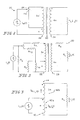
- FIG. 3 illustrates an ideal four-to-one step-down transformer 40 .
- transformer cores have been omitted from the illustrations that follow.
- any practical turns ratio is achievable.
- the transformer 40 is idealized.
- permeability of the core 44 is assumed to be infinite, and the core loss is assumed to be zero. Winding resistance is also assumed to be zero.
- the current from the current source must divide such that the ampere turns created by the two sections 42 a, 42 b of the winding 42 in the autotransformer 40 neutralize each other. Since section 42 b of winding 42 has three times the turns of section 42 a, the current must divide such that 3 ⁇ 4 of the current of i in (t) flows into section 42 a of winding 42 and 1 ⁇ 4 of the current flows into section 42 b of winding 42 . This provides 3 ⁇ 4 i in (t) ⁇ n ampere-turns flowing in each of sections 42 a , 42 b , but in opposite directions. Since the current in section 42 b of winding 42 is 1 ⁇ 4 i in (t) and this is also the output current, i o (t), autotransformer 40 is a four-to-one step-down transformer.
- FIG. 4 A similar analysis can be performed for a step-up current autotransformer configuration. Such a configuration is illustrated in FIG. 4 .
- the transformer 50 is considered ideal. Permeability of the core 54 is infinite and the core loss is zero. Winding 52 resistance is zero. The load resistor R L is also assumed to be zero (a short circuit).
- the currents in sections 52 a , 52 b of the winding 52 must be such that the ampere turns created by these two sections 52 a , 52 b of the winding 52 neutralize each other. Since there are 3n ⁇ i in (t) ampere-turns in section 52 b there must be a current of 3i in (t) in the n turn coil section 52 a .
- the current into the load R L is the sum of the currents in the n and 3n turn coil sections 52 b , 52 a , respectively, and therefore equals 4i in (t).
- a four-to-one step-up transformer has been realized with autotransformer 50 .
- the current flow in the output is directly proportional to the input current and inversely proportional to the ratio of the number of turns of the winding which drive the load divided by the number of turns of the winding driven by the input current source.
- FIG. 5 illustrates a schematic diagram of a practical step-down current ranger using an autotransformer.
- current ranger autotransformer 60 is illustrated as a one-to-one and a four-to-one step-down transformer. Other ratios and other numbers of taps are clearly available, and do not impact the availability of autotransformers as current transformers.
- the ideal transformer 60 is the transformer formed by the 3n turn and n turn windings 62 b and 62 a.
- the resistors R 1 and R 2 represent the resistances associated with the 3n turn and n turn winding sections 62 b and 62 a.
- the resistor R 1 represents the core loss.
- the inductor L m represents the magnetizing current of the autotransformer 60 .
- the resistor R L represents the load resistance.
- the resistor R g represents the source impedance of the non-ideal current source i in (t).
- resistors R c , R 1 and R 2 are to reduce the size of the core.
- the core losses decrease, and the effective value of R c increases.
- the mean length per turn of the windings 62 also decreases.
- the winding resistances R 1 and R 2 decrease as direct results of the decrease in the mean length per turn of the windings 62 .
- transformer cost usually decreases.
- the value of the magnetizing inductance L m also decreases.
- L m permits current to flow in (a) section(s) 62 a , 62 b of the autotransformer 60 that are not counterbalanced by ampere-turns of current flow in the other section(s) 62 b , 62 a of the windings 62 .
- the transformer action is thus bypassed.
- the values of the parasitic elements determine the magnitude(s) of this (these) current flow(s). This results in errors in the current ratios in the different sections 62 a , 62 b of the autotransformer 60 . Reducing the value of L m increases this effect. Even with electronic compensation, it may be difficult to make the value of L m high enough to render the unbalanced current error negligible for the accuracy desired.
- resistor R g is normally much, much larger than R 1 , R 2 , and R L , and since it only affects the error of the non-ideal current source i in (t), and not the transformer 60 , R g can be ignored for the purposes of this analysis.
- the output current i o (t) is proportional to the input current i in (t) and inversely proportional to the ratio of the resistance encompassed by the output load, R 1 +R 2 , divided by the resistance encompassed by the input current source, R 1 .
- This is very similar to the current division produced by the autotransformer 60 itself. If the values of R 1 and R 2 are arranged to be proportional to the number of turns in each coil section 62 a , 62 b , then the current division caused by the winding resistances' resistive divider exactly matches the current division caused by the autotransformer 60 's action.
- the effect of the loss in accuracy caused by the presence of the parasitic inductance L m can be substantially reduced.
- the parasitic winding resistances have been arranged to provide the same current division as that provided by the transformer 60 's action.
- the autotransformer 60 tends to maintain its accuracy without regard to variation in the value of L m , whether resulting from shrinking core size, changing drive frequency, or whatever other source. If the resistances can be perfectly balanced, there is no error, even at DC. By making the winding resistances proportional to their turns, more accurate step-down autotransformers can be constructed with less material and thus less cost.
- R L be negligible when compared to R 2 . Because considerable effort is expended to make R 2 as small as possible, R L must be made very close to zero for this assumption, and the circuit analysis based upon it, to hold.
- One method for making R L approach zero is to use the virtual ground characteristics of an operational amplifier (hereinafter sometimes op-amp) to make R L approach zero ohms. This approach is illustrated in FIG. 7 .
- the non-inverting (+) input terminal of an op-amp 66 is one terminal of R L and the inverting ( ⁇ ) input terminal of op-amp 66 is the other terminal of R L .
- the + input terminal of op-amp 66 is coupled to ground to help prevent the common mode range of op-amp 66 from being exceeded. Typically, this does not cause any problems in the rest of the circuit.
- a resistor 68 is coupled from the output terminal of op-amp 66 to its ⁇ input terminal.
- the output voltage of op-amp 66 varies in such a way that any current at its ⁇ input terminal passes through resistor 68 .
- Op-amp 66 performs a current-to-voltage conversion.
- the output voltage of op-amp 66 is roughly equal to the current at its ⁇ input terminal times the value of resistor 68 . If op-amp 66 has infinite gain, no voltage appears across its + and ⁇ input terminals, and the load impedance R L is zero. If op-amp 66 has a finite gain A, then the output voltage divided by the op-amp gain A appears across the + and ⁇ input terminals.
- FIG. 8 An improved circuit is illustrated in FIG. 8 .
- the circuit illustrated in FIG. 8 reduces to zero the resistance of the feedback resistor 68 .
- the circuit of FIG. 8 also adds two floating, two-terminal operating voltage supplies 72 , 74 for op-amp 76 , for reasons that will become clear.
- the circuit illustrated in FIG. 8 makes use of the virtual ground of the op-amp 76 to provide an essentially zero ohm load, but avoids the need for a current-to-voltage conversion.
- This circuit presents substantially zero ohms as its effective impedance R L ′, but outputs a current i o (t) which is nearly independent of the value of the load resistor R L .
- the op-amp 76 attempts to keep the voltage difference across its + and ⁇ input terminals at zero. Since no current can flow into the + or ⁇ input terminals of op-amp 76 , the current i L (t) must flow into the output terminal of op-amp 76 . Because the power supplies 72 , 74 are floating, that is, coupled only to the op-amp 76 , the current into the output of op-amp 76 goes through the op-amp 76 , out through the power supply terminals of op-amp 76 , through the floating supplies 72 , 74 , and into the load resistor R L of the circuit as i o (t). Additional circulating current flows through the power supplies 72 , 74 and op-amp 76 in order to power the op-amp 76 , but it cannot leave the loop.
- the effectiveness of the circuit illustrated in FIG. 8 is somewhat harder to evaluate than the circuit illustrated in FIG. 7 .
- Error from the finite gain A of the op-amp 76 and the finite common mode rejection of the op-amp 76 appear as voltage at v L ′(t).
- the output voltage of the op-amp 76 must first be determined.
- the output voltage, v L ′(t), of the op-amp 76 is the difference between the voltage at the output terminal of op-amp 76 and the ground of the power supplies 72 , 74 of op-amp 76 .
- the output voltage of op-amp 76 is the difference between the voltage, v L (t), across R L and the output v L ′(t) of the op-amp 76 .
- v L ′(t) is much, much smaller-than v L (t)
- v L (t) will be used throughout the remainder of this analysis as the output voltage of the op-amp 76 .
- This voltage divided by the op-amp gain, A appears across the input terminals of the op amp 76 .
- the common mode rejection of the op-amp 76 also contributes to the output voltage of the op-amp 76 . Because the + and ⁇ input terminals of op-amp 76 remain at ground potential, and the supplies move with v L (t), the + and ⁇ inputs see a common mode voltage equal to v L (t). From the definition of the common mode rejection ratio G, the common mode voltage divided by the common mode rejection ratio, G, also appears across the + and ⁇ input terminals. As noted, the voltage v L (t) is the common mode voltage and that this voltage divided by the common mode rejection ratio, G, appears across the + and ⁇ input terminals of the op-amp 76 .
- R L ′ is v L ′/i L (t)
- the effective impedance R L ′ of the circuit is ⁇ (A+G) ⁇ R L ⁇ /AG.
- a and G are very large, as they tend to be in an op-amp, and R L is small, as it usually is by design, the impedance R L ′ is quite small.
- the circuit illustrated in FIG. 8 thus improves upon the performance of the circuit illustrated in FIG. 7 , first in the magnitude of the load impedance it presents, and second in that it does not require the next stage to have a floating input, nor does it require a current-to-voltage-to-current conversion.
- FIG. 9 illustrates the limiting case in which L m has shorted out the transformer 80 and current is being steered by the parasitic winding resistances R 1 and R 2 .
- the op-amp current buffer 82 as described in connection with FIG. 8 has been incorporated into this model. As can be seen, the current from the current source passes through R 2 and then directly into the output of the current buffer 82 . Because the current buffer 82 has substantially zero ohms output impedance, even when compared to the typically quite low resistance of R 1 , no current flows through R 1 .
- R 1 and R 2 a current divider that mirrors the current divider formed by the autotransformer winding. This variation is illustrated in FIG. 10 .
- the negative feedback to the op-amp 86 has been moved from the output of the op-amp 86 to the node at which R 2 is coupled to the current source i in (t).
- the source impedance R g for the non-ideal current source i in (t) has been added back to the model for reasons which will become clear. Moving the negative feedback to the op-amp 86 to the node at which R 2 is coupled to the current source i in (t) changes the manner in which voltage is applied to resistors R 1 and R 2 .
- op-amp 86 adjusts the voltage applied at its output to keep the voltage at the node at which R 2 is coupled to the current source i in (t) the same as the voltage at the node at which R 1 is coupled to the current source i in (t). Since i in (t) must flow through R 2 , the voltage across R 2 must be i in (t) ⁇ R 2 . Because the node at which R 1 is coupled to the current source i in (t) is at the same potential as the node at which R 2 is coupled to the current source i in (t) and the remaining terminals of R 1 and R 2 are joined, R 1 and R 2 have equal and opposite potentials across them.
- Another benefit of relocating the feedback winding to the common node of R 2 and the current source i in (t) is that the entire load of the winding resistances is supplied by the op-amp 86 .
- the voltage seen by the current source i in (t) is zero. This means that the current source i in (t) is working into a short and no error current flows in R g . This eliminates another source of error.
- the voltage across the autotransformer is clamped at zero volts, there is no flux in the core of the autotransformer.
- Both step-up and step-down transformers can be combined in a switching arrangement that creates an autotransformer providing both step-up and step-down capabilities.
- Such an arrangement provides a wide range of ratios.
- FIG. 11 A three-section current ranger 90 provides windings 90 a , 90 b, 90 c with ratios 90 a :( 90 a + 90 b ), ( 90 a + 90 b ):( 90 a + 90 b + 90 c ) in multiples of 4. (The windings' parasitic resistances are illustrated.)
- Such a current ranger can, of course, be designed with any desired step sizes and any number of winding sections.
- Two switches 92 , 94 are provided for selecting the taps.
- Switch 94 selects the tap 96 a, 96 b , 96 c used by the load R L as reflected at the output terminal of op-amp 98 , and switch 92 selects the tap 96 a , 96 b , 96 c used by the input i in (t).
- the ratios that can be achieved in this specific example are illustrated in the following table.
- n taps there are n 2 unique settings. There are not, however, n 2 unique ratios. Many of the ratios are duplicated. In the illustrated embodiment, there are three ways of achieving the 1:1 ratio, two ways of achieving the 4:1 ratio, and two ways of achieving the 1:4 ratio. There are five unique ratios. This is a significant improvement over prior art current rangers, because without the step-up, step-down technique two additional windings would have had to be added to a current ranger to achieve five ratios. Adding the required switching is far less expensive than adding the two more windings to a prior art current ranger.
Landscapes
- Engineering & Computer Science (AREA)
- Power Engineering (AREA)
- Automation & Control Theory (AREA)
- Electromagnetism (AREA)
- General Physics & Mathematics (AREA)
- Radar, Positioning & Navigation (AREA)
- Physics & Mathematics (AREA)
- Ac-Ac Conversion (AREA)
- Transformers For Measuring Instruments (AREA)
- Amplifiers (AREA)
- Control Of Electrical Variables (AREA)
- Measurement Of Optical Distance (AREA)
- Coils Or Transformers For Communication (AREA)
Priority Applications (1)
| Application Number | Priority Date | Filing Date | Title |
|---|---|---|---|
| US10/380,397 US6879232B2 (en) | 2000-09-15 | 2001-09-11 | Wide ratio autotransformer-type current ranging |
Applications Claiming Priority (4)
| Application Number | Priority Date | Filing Date | Title |
|---|---|---|---|
| US23271900P | 2000-09-15 | 2000-09-15 | |
| US60232719 | 2000-09-15 | ||
| PCT/US2001/042116 WO2002023301A1 (fr) | 2000-09-15 | 2001-09-11 | Mesure de courant du type a autotransformateur a rapport large |
| US10/380,397 US6879232B2 (en) | 2000-09-15 | 2001-09-11 | Wide ratio autotransformer-type current ranging |
Publications (2)
| Publication Number | Publication Date |
|---|---|
| US20030151482A1 US20030151482A1 (en) | 2003-08-14 |
| US6879232B2 true US6879232B2 (en) | 2005-04-12 |
Family
ID=22874259
Family Applications (1)
| Application Number | Title | Priority Date | Filing Date |
|---|---|---|---|
| US10/380,397 Expired - Lifetime US6879232B2 (en) | 2000-09-15 | 2001-09-11 | Wide ratio autotransformer-type current ranging |
Country Status (9)
| Country | Link |
|---|---|
| US (1) | US6879232B2 (fr) |
| EP (1) | EP1325394B1 (fr) |
| AU (1) | AU2001293271A1 (fr) |
| BR (1) | BRPI0113913B1 (fr) |
| CA (2) | CA2689788C (fr) |
| DE (1) | DE60139265D1 (fr) |
| DK (1) | DK1325394T3 (fr) |
| ES (1) | ES2330922T3 (fr) |
| WO (1) | WO2002023301A1 (fr) |
Cited By (2)
| Publication number | Priority date | Publication date | Assignee | Title |
|---|---|---|---|---|
| US20140160820A1 (en) * | 2012-12-10 | 2014-06-12 | Grid Sentry LLC | Electrical Current Transformer for Power Distribution Line Sensors |
| US9337638B2 (en) | 2013-01-29 | 2016-05-10 | Grid Sentry LLC | Clamp mechanism for power distribution line sensors |
Families Citing this family (4)
| Publication number | Priority date | Publication date | Assignee | Title |
|---|---|---|---|---|
| US8922315B2 (en) * | 2011-05-17 | 2014-12-30 | Bae Systems Information And Electronic Systems Integration Inc. | Flexible ultracapacitor cloth for feeding portable electronic device |
| KR101514491B1 (ko) * | 2011-12-08 | 2015-04-23 | 삼성전기주식회사 | 코일 부품 및 그 제조방법 |
| KR101792274B1 (ko) * | 2012-08-08 | 2017-11-01 | 삼성전기주식회사 | 노이즈 제거 필터 |
| US10044187B2 (en) | 2015-04-30 | 2018-08-07 | Abb Schweiz Ag | AC network power flow control |
Citations (8)
| Publication number | Priority date | Publication date | Assignee | Title |
|---|---|---|---|---|
| US3814866A (en) * | 1971-09-30 | 1974-06-04 | Reliable Electric Co | Negative resistance repeater |
| US3952256A (en) * | 1974-07-25 | 1976-04-20 | Unicord Incorporated | Multi-impedance output for transistor power amplifier |
| US4107620A (en) * | 1976-10-12 | 1978-08-15 | Forbro Design Corp. | Regulated power supply with auto-transformer output and direct current feedback |
| US5054076A (en) * | 1989-11-13 | 1991-10-01 | Lowell Manufacturing Company | Key-actuated volume control |
| US6087738A (en) * | 1998-08-20 | 2000-07-11 | Robicon Corporation | Variable output three-phase transformer |
| US6348782B1 (en) * | 1998-10-02 | 2002-02-19 | Powerware Corporation | Uninterruptible power supply systems, voltage regulators and operating methods employing controlled ferroresonant transformer circuits |
| US6414412B1 (en) * | 2000-08-21 | 2002-07-02 | Chung-Hsin Hao | Variable speed motor with tapped starting winding |
| US6417651B1 (en) * | 2000-05-02 | 2002-07-09 | James W. Kronberg | Digitally-controlled AC voltage stabilizer |
Family Cites Families (9)
| Publication number | Priority date | Publication date | Assignee | Title |
|---|---|---|---|---|
| US2885639A (en) * | 1956-05-28 | 1959-05-05 | Duncan Electric Co Inc | Dual-range meters |
| US3815013A (en) * | 1972-06-14 | 1974-06-04 | Gen Electric | Current transformer with active load termination |
| US4480214B2 (en) * | 1982-04-16 | 1991-04-16 | Starter circuit for gaseous discharge lamp | |
| US4733158A (en) * | 1986-08-21 | 1988-03-22 | Datametrics Corporation | Control circuit for tap-switching power supplies and multi-tap transformers |
| US5276394A (en) * | 1992-06-26 | 1994-01-04 | Radian Research, Inc. | Compensated transformers |
| US5652479A (en) * | 1995-01-25 | 1997-07-29 | Micro Linear Corporation | Lamp out detection for miniature cold cathode fluorescent lamp system |
| US5754012A (en) * | 1995-01-25 | 1998-05-19 | Micro Linear Corporation | Primary side lamp current sensing for minature cold cathode fluorescent lamp system |
| US5604669A (en) * | 1995-03-28 | 1997-02-18 | Northrop Grumman Corporation | Resonant, current mode regulated, half-bridge power supply |
| WO1998057417A1 (fr) * | 1997-06-13 | 1998-12-17 | Koninklijke Philips Electronics N.V. | Alimentation a decoupage |
-
2001
- 2001-09-11 EP EP01973718A patent/EP1325394B1/fr not_active Expired - Lifetime
- 2001-09-11 DE DE60139265T patent/DE60139265D1/de not_active Expired - Lifetime
- 2001-09-11 CA CA2689788A patent/CA2689788C/fr not_active Expired - Lifetime
- 2001-09-11 US US10/380,397 patent/US6879232B2/en not_active Expired - Lifetime
- 2001-09-11 WO PCT/US2001/042116 patent/WO2002023301A1/fr active Application Filing
- 2001-09-11 BR BRPI0113913-4A patent/BRPI0113913B1/pt active IP Right Grant
- 2001-09-11 DK DK01973718T patent/DK1325394T3/da active
- 2001-09-11 CA CA2422689A patent/CA2422689C/fr not_active Expired - Lifetime
- 2001-09-11 ES ES01973718T patent/ES2330922T3/es not_active Expired - Lifetime
- 2001-09-11 AU AU2001293271A patent/AU2001293271A1/en not_active Abandoned
Patent Citations (8)
| Publication number | Priority date | Publication date | Assignee | Title |
|---|---|---|---|---|
| US3814866A (en) * | 1971-09-30 | 1974-06-04 | Reliable Electric Co | Negative resistance repeater |
| US3952256A (en) * | 1974-07-25 | 1976-04-20 | Unicord Incorporated | Multi-impedance output for transistor power amplifier |
| US4107620A (en) * | 1976-10-12 | 1978-08-15 | Forbro Design Corp. | Regulated power supply with auto-transformer output and direct current feedback |
| US5054076A (en) * | 1989-11-13 | 1991-10-01 | Lowell Manufacturing Company | Key-actuated volume control |
| US6087738A (en) * | 1998-08-20 | 2000-07-11 | Robicon Corporation | Variable output three-phase transformer |
| US6348782B1 (en) * | 1998-10-02 | 2002-02-19 | Powerware Corporation | Uninterruptible power supply systems, voltage regulators and operating methods employing controlled ferroresonant transformer circuits |
| US6417651B1 (en) * | 2000-05-02 | 2002-07-09 | James W. Kronberg | Digitally-controlled AC voltage stabilizer |
| US6414412B1 (en) * | 2000-08-21 | 2002-07-02 | Chung-Hsin Hao | Variable speed motor with tapped starting winding |
Cited By (2)
| Publication number | Priority date | Publication date | Assignee | Title |
|---|---|---|---|---|
| US20140160820A1 (en) * | 2012-12-10 | 2014-06-12 | Grid Sentry LLC | Electrical Current Transformer for Power Distribution Line Sensors |
| US9337638B2 (en) | 2013-01-29 | 2016-05-10 | Grid Sentry LLC | Clamp mechanism for power distribution line sensors |
Also Published As
| Publication number | Publication date |
|---|---|
| CA2689788A1 (fr) | 2002-03-21 |
| WO2002023301A8 (fr) | 2002-07-04 |
| EP1325394A1 (fr) | 2003-07-09 |
| AU2001293271A1 (en) | 2002-03-26 |
| CA2422689C (fr) | 2010-03-30 |
| CA2689788C (fr) | 2012-08-07 |
| BRPI0113913B1 (pt) | 2015-07-14 |
| DK1325394T3 (da) | 2009-10-26 |
| DE60139265D1 (de) | 2009-08-27 |
| US20030151482A1 (en) | 2003-08-14 |
| BR0113913A (pt) | 2004-02-10 |
| ES2330922T3 (es) | 2009-12-17 |
| WO2002023301A9 (fr) | 2002-12-27 |
| WO2002023301A1 (fr) | 2002-03-21 |
| EP1325394B1 (fr) | 2009-07-15 |
| CA2422689A1 (fr) | 2002-03-21 |
| EP1325394A4 (fr) | 2006-04-19 |
Similar Documents
| Publication | Publication Date | Title |
|---|---|---|
| US7768369B2 (en) | Method and apparatus for substantially reducing electrical earth displacement current flow generated by wound components without requiring additional windings | |
| US7378929B2 (en) | Method and apparatus for substantially reducing electrical displacement current flow between input and output circuits coupled to input and output windings of an energy transfer element | |
| JP4125903B2 (ja) | 巻かれた部品によって生成される電気アース変位電流をほぼ低減する方法および装置 | |
| US5345169A (en) | Current measuring device | |
| US20080192960A1 (en) | Hybrid Filter for Audio Switching Amplifier | |
| US6879232B2 (en) | Wide ratio autotransformer-type current ranging | |
| EP3739601B1 (fr) | Convertisseur llc entrelacé | |
| US10840012B2 (en) | Single input circuit for receiving output from a di/dt sensor or current transformer and circuit breaker including same | |
| JPH01223520A (ja) | 直流電源 | |
| JPH07506180A (ja) | 交流電流によって励磁される複数の負荷を多重化するための電子装置 | |
| KR100737061B1 (ko) | 이중 정격 전류 변압기 회로 | |
| EP0528658A1 (fr) | Technique pour examiner un courant de travail | |
| WO1995011549A1 (fr) | Circuit appliquant un courant continu | |
| SU1449930A1 (ru) | Симметричный трансформаторный преобразователь сопротивлени | |
| JPS6328015A (ja) | 単巻変圧器 | |
| Driessen et al. | Reduction of the number of power amplifiers for an advanced single-stage planar actuator | |
| JPH0697243B2 (ja) | 反射係数測定用ブリッジ | |
| CN112509898A (zh) | 一种电子束加工设备扫描系统 | |
| JPS646402B2 (fr) | ||
| JPH0514070A (ja) | プツシユプル増幅器バイアス回路 | |
| JPS63175567A (ja) | 直流重畳回路 |
Legal Events
| Date | Code | Title | Description |
|---|---|---|---|
| AS | Assignment |
Owner name: RADIAN RESEARCH, INC., INDIANA Free format text: ASSIGNMENT OF ASSIGNORS INTEREST;ASSIGNOR:MAYFIELD, GLENN A.;REEL/FRAME:012378/0553 Effective date: 20010907 |
|
| STCF | Information on status: patent grant |
Free format text: PATENTED CASE |
|
| FPAY | Fee payment |
Year of fee payment: 4 |
|
| AS | Assignment |
Owner name: KEYBANK NATIONAL ASSOCIATION, INDIANA Free format text: SECURITY AGREEMENT;ASSIGNOR:RADIAN RESEARCH, INC.;REEL/FRAME:026838/0463 Effective date: 20110819 |
|
| FPAY | Fee payment |
Year of fee payment: 8 |
|
| AS | Assignment |
Owner name: RADIAN RESEARCH, INC., INDIANA Free format text: RELEASE BY SECURED PARTY;ASSIGNOR:KEYBANK NATIONAL ASSOCIATION;REEL/FRAME:030608/0682 Effective date: 20130531 Owner name: FIRST FINANCIAL BANK, NATIONAL ASSOCIATION, OHIO Free format text: SECURITY AGREEMENT;ASSIGNOR:RADIAN RESEARCH, INC.;REEL/FRAME:030611/0186 Effective date: 20130531 |
|
| FPAY | Fee payment |
Year of fee payment: 12 |
|
| AS | Assignment |
Owner name: RADIAN RESEARCH, INC., INDIANA Free format text: RELEASE BY SECURED PARTY;ASSIGNOR:FIRST FINANCIAL BANK, OHIO STATE CHARTERED BANK F/K/A FIRST FINANCIAL BANK, NATIONAL ASSOCIATION;REEL/FRAME:056837/0478 Effective date: 20210630 |