US6856888B2 - Vehicular control system - Google Patents
Vehicular control system Download PDFInfo
- Publication number
- US6856888B2 US6856888B2 US10/806,374 US80637404A US6856888B2 US 6856888 B2 US6856888 B2 US 6856888B2 US 80637404 A US80637404 A US 80637404A US 6856888 B2 US6856888 B2 US 6856888B2
- Authority
- US
- United States
- Prior art keywords
- value
- target
- error
- gain
- multiplying
- Prior art date
- Legal status (The legal status is an assumption and is not a legal conclusion. Google has not performed a legal analysis and makes no representation as to the accuracy of the status listed.)
- Expired - Fee Related
Links
Images
Classifications
-
- F—MECHANICAL ENGINEERING; LIGHTING; HEATING; WEAPONS; BLASTING
- F02—COMBUSTION ENGINES; HOT-GAS OR COMBUSTION-PRODUCT ENGINE PLANTS
- F02D—CONTROLLING COMBUSTION ENGINES
- F02D41/00—Electrical control of supply of combustible mixture or its constituents
- F02D41/02—Circuit arrangements for generating control signals
- F02D41/14—Introducing closed-loop corrections
- F02D41/1401—Introducing closed-loop corrections characterised by the control or regulation method
- F02D41/1402—Adaptive control
-
- F—MECHANICAL ENGINEERING; LIGHTING; HEATING; WEAPONS; BLASTING
- F02—COMBUSTION ENGINES; HOT-GAS OR COMBUSTION-PRODUCT ENGINE PLANTS
- F02D—CONTROLLING COMBUSTION ENGINES
- F02D11/00—Arrangements for, or adaptations to, non-automatic engine control initiation means, e.g. operator initiated
- F02D11/06—Arrangements for, or adaptations to, non-automatic engine control initiation means, e.g. operator initiated characterised by non-mechanical control linkages, e.g. fluid control linkages or by control linkages with power drive or assistance
- F02D11/10—Arrangements for, or adaptations to, non-automatic engine control initiation means, e.g. operator initiated characterised by non-mechanical control linkages, e.g. fluid control linkages or by control linkages with power drive or assistance of the electric type
-
- F—MECHANICAL ENGINEERING; LIGHTING; HEATING; WEAPONS; BLASTING
- F02—COMBUSTION ENGINES; HOT-GAS OR COMBUSTION-PRODUCT ENGINE PLANTS
- F02D—CONTROLLING COMBUSTION ENGINES
- F02D41/00—Electrical control of supply of combustible mixture or its constituents
- F02D41/24—Electrical control of supply of combustible mixture or its constituents characterised by the use of digital means
- F02D41/2406—Electrical control of supply of combustible mixture or its constituents characterised by the use of digital means using essentially read only memories
- F02D41/2425—Particular ways of programming the data
- F02D41/2429—Methods of calibrating or learning
- F02D41/2451—Methods of calibrating or learning characterised by what is learned or calibrated
- F02D41/2454—Learning of the air-fuel ratio control
- F02D41/2461—Learning of the air-fuel ratio control by learning a value and then controlling another value
-
- F—MECHANICAL ENGINEERING; LIGHTING; HEATING; WEAPONS; BLASTING
- F02—COMBUSTION ENGINES; HOT-GAS OR COMBUSTION-PRODUCT ENGINE PLANTS
- F02D—CONTROLLING COMBUSTION ENGINES
- F02D41/00—Electrical control of supply of combustible mixture or its constituents
- F02D41/02—Circuit arrangements for generating control signals
- F02D41/14—Introducing closed-loop corrections
- F02D41/1401—Introducing closed-loop corrections characterised by the control or regulation method
- F02D2041/141—Introducing closed-loop corrections characterised by the control or regulation method using a feed-forward control element
-
- F—MECHANICAL ENGINEERING; LIGHTING; HEATING; WEAPONS; BLASTING
- F02—COMBUSTION ENGINES; HOT-GAS OR COMBUSTION-PRODUCT ENGINE PLANTS
- F02D—CONTROLLING COMBUSTION ENGINES
- F02D41/00—Electrical control of supply of combustible mixture or its constituents
- F02D41/02—Circuit arrangements for generating control signals
- F02D41/14—Introducing closed-loop corrections
- F02D41/1401—Introducing closed-loop corrections characterised by the control or regulation method
- F02D2041/1413—Controller structures or design
- F02D2041/1423—Identification of model or controller parameters
Definitions
- the present invention relates to a vehicular control system disposed with a feedforward control function.
- vehicular control systems such as described in Japanese Patent No. 3316955 where a controlled system is modeled, a model constant is calculated in real time, a feedback gain is calculated on the basis of the model constant, and a controlled value of a controlled system is made to follow a target value to conduct feedback control.
- An object of the present invention is to provide a vehicular control system that can conduct feedforward control reflecting the effects resulting from characteristic variations in a controlled system and can execute highly responsive and highly precise feedforward control.
- the invention provides a vehicular control system that conducts feedforward control so that a controlled value of a controlled system disposed in a vehicle is made to follow a target value
- the vehicular control system comprising: gain calculating means for adaptively determining a gain based on a value obtained by multiplying a derivative value of the target value by the error between the target value and the actual controlled value; and feedforward corrected value calculating means for determining, as a feedforward corrected value, a value obtained by multiplying the gain by the derivative value of the target value.
- the gain can be automatically adjusted in accordance with characteristic variations in the controlled system, feedforward control reflecting effects resulting from characteristic variations in the controlled system can be conducted, and the control precision of feedforward control can be improved.
- control equation that calculates the input (control input) of the controlled system from the target value serves as an inverse model of the transfer function of the controlled system, as will be described later, the output (controlled value) of the controlled system can be made to match the target value and highly responsive feedforward control can be realized.
- the derivative value of the target value used in calculating the feedforward corrected value becomes 0 in a steady state where the target value does not change, the effects of steady-state deviation between the target value and the actual controlled value can be eliminated by multiplying the derivative value of the target value.
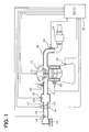
- FIG. 1 is a diagram showing the schematic configuration of an entire engine control system in a first embodiment of the invention
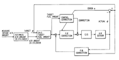
- FIG. 2 is a block diagram describing a derivation method of a control expression used in the first embodiment
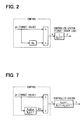
- FIG. 3 is a flow chart showing the flow of processing of an electronic throttle control program of the first embodiment
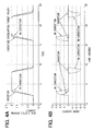
- FIGS. 4A and 4B are time charts describing an example of the electronic throttle control of the first embodiment
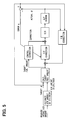
- FIG. 5 is a block diagram describing an air-fuel ratio control system of a second embodiment
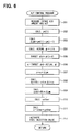
- FIG. 6 is a flow chart showing the flow of processing of an air-fuel control program of the second embodiment
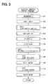
- FIG. 7 is a block diagram describing a derivation method of a control expression used in a third embodiment
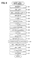
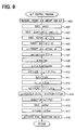
- FIG. 8 is a flow chart showing the flow of processing of an electronic throttle control program of the third embodiment
- FIG. 9 is a flow chart showing the flow of processing of an air-fuel ratio control program of a fourth embodiment.
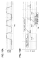
- FIGS. 10A and 10B are time charts describing an example of the air-fuel ratio control of the fourth embodiment.
- FIGS. 1 to 4 B A first embodiment where the invention is applied to an electronic throttle system will be described below on the basis of FIGS. 1 to 4 B.
- FIG. 1 A schematic configuration of an entire engine control system is described on the basis of FIG. 1 .
- An air cleaner 13 is disposed at the most upstream portion of an intake pipe 12 of an engine 11 , which is an internal combustion engine, and an air flow meter 14 that detects the intake air amount is disposed at a downstream side of the air cleaner 13 .
- a throttle valve 15 whose opening is adjusted by a motor 17 such as a DC motor and a throttle opening sensor 16 that detects the throttle opening are disposed at a downstream side of the air flow meter 14 .
- a surge tank 12 a is disposed at a downstream side of the throttle valve 15 , and an intake pipe pressure sensor 18 that detects the intake pipe pressure is disposed at the surge tank 12 a .
- An intake manifold 19 that introduces air to each cylinder of the engine 11 is disposed at the surge tank 12 a , and a fuel injection valve 20 that injects fuel is attached in the vicinity of an intake port of the intake manifold 19 of each cylinder.
- a spark plug 21 is attached to each cylinder at a cylinder head of the engine 11 . Mixed air inside the pipes is combusted by the spark discharge of each spark plug 21 .
- a catalyst 23 such as a three-way catalyst that purifies CO, HC and NOx in exhaust gas is disposed at an exhaust pipe 22 of the engine 11 , and an air-fuel ratio sensor 24 (or oxygen sensor) that detects the air-fuel ratio of the exhaust gas is disposed at an upstream side of the catalyst 23 .
- a water temperature sensor 25 that detects the cooling water temperature and a crank angle sensor 26 that outputs a pulse signal each time a crankshaft of the engine 11 revolves by a constant crank angle (e.g., 30° CA) are disposed at a cylinder block of the engine 11 . The crank angle and the engine revolving speed are detected on the basis of the output signal of the crank angle sensor 26 .
- the output of each sensor is inputted to an engine control circuit (represented below as “ECU”) 27 .
- the ECU 27 is mainly configured by a microcomputer and executes various engine control programs stored in an internally disposed ROM (Read Only Memory), whereby the ECU 27 controls the fuel injection amount of the fuel injection valve 20 and the ignition timing of the spark plugs 21 depending on an operation state of the engine.
- the ECU 27 uses an electronic throttle system as feedforward control (represented below as “F/F control”) and feedback control (represented below as “F/B control”) to control the throttle opening to a target throttle opening set in accordance with an accelerator opening (accelerator control input) detected by an accelerator sensor (not shown).
- F/F control feedforward control
- F/B control feedback control
- the ECU 27 executes a later-described electronic throttle control program of FIG. 3 , whereby the ECU 27 corrects, by adaptive control, excess and deficiency with the F/F control and the F/B control.
- a control used in the electronic throttle control program of FIG. 3 will be described below.
- a controlled system electronic throttle system
- a first-order lag system In this case, an output y (actual throttle opening) of the controlled system can be made to match a target value ym (target throttle opening) as long as the control (inverse model of transfer function of the controlled system) in the dotted lines of FIG. 2 can be realized.
- Kh ⁇ K is guaranteed by adjusting Kh (estimated value of the time constant K).
- the controlled value y can be made to match the target value ym.
- the ECU 27 periodically executes the electronic throttle control program of FIG. 3 , whereby it functions as gain calculating means and feedforward corrected value calculating means which are referred to in the present invention, the ECU 27 adaptively determines the gain Kh (estimated value of the time constant K) on the basis of a value z obtained by multiplying a derivative value ⁇ ym of the target throttle opening by the error e between the target throttle opening ym (target value) and the actual throttle opening y (actual controlled value), and determines, as the F/F corrected value ucmp, a value obtained by multiplying the derivative value ⁇ ym of the target throttle opening by the gain Kh.
- Kh estimated value of the time constant K
- step 101 the actual throttle opening y (actual controlled value) is measured in step 101 by the throttle opening sensor 16 , and the target throttle opening ym (i) is calculated in step 102 on the basis of the accelerator opening. Thereafter, the program proceeds to step 103 , where the difference value ⁇ ym (derivative value of the target value) between the current value ym (i) of the target throttle opening and the previous value ym (i ⁇ 1) is calculated.
- ⁇ ym ym ( i ) ⁇ ym ( i ⁇ 1)
- Kh (i ⁇ 1) is the previous gain
- ⁇ k is a constant (>0)
- ⁇ t is the control period.
- step 108 the target throttle opening difference value ⁇ ym is multiplied by the gain Kh to determine the F/F corrected value ucmp.
- step 109 another corrected value uother such as an F/B corrected value is calculated.
- step 110 the other corrected value uother is added to the F/F corrected value ucmp to determine the control input u.
- u ucmp+uother
- the program may also be configured so that ucmp and uother are determined by a correction factor and ucmp and uother are multiplied by a base value to determine the control input u.
- step 111 the motor 17 is driven by the control input u so that the actual throttle opening y is made to match the target throttle opening ym.
- the electronic throttle system is configured so that the F/F control is corrected by adaptive control.
- the gain Kh of the F/F control can be automatically adjusted in accordance with characteristic variations in the controlled system (electronic throttle system), F/F control reflecting effects resulting from changes in the characteristics of the controlled system can be conducted, and the control precision of the F/F control can be improved.
- the control equation calculating the input (control input u) of the controlled system from the target throttle opening ym (target value) serves as an inverse model of the transfer function of the controlled system, the output of the controlled system (actual throttle opening y) can be made to match the target value (target throttle opening ym), and highly responsive F/F control can be realized.
- the target throttle opening ym target value
- the actual throttle opening y actual controlled value
- highly responsive and highly precise electronic throttle control can be realized by correction resulting from adaptive control in comparison to a conventional system where there is no correction resulting from adaptive control.
- the gain Kh is adaptively determined on the basis of the value z obtained by multiplying the target fuel amount difference value ⁇ ym (derivative value of the target fuel amount) by the error e between the target excess fuel ratio (represented below as “target ⁇ ”) and the actual excess fuel ratio (represented below as “actual ⁇ ”) detected by the air-fuel ratio sensor 24 , and a value obtained by multiplying the target fuel amount difference value ⁇ ym by the gain Kh is determined as the F/F corrected value ucmp.
- step 201 When the program is started, first the intake air amount and the air-fuel ratio are measured in step 201 , and the target fuel amount ym (i) is calculated in step 202 on the basis of the intake air amount. Thereafter, the program proceeds to step 203 , where the difference value ⁇ ym (derivative value of the target value) between the current value ym (i) of the target fuel amount and the previous value ym (i ⁇ 1) is calculated.
- ⁇ ym ym ( i ) ⁇ ym ( i ⁇ 1)
- Kh (i ⁇ 1) is the previous gain
- ⁇ k is a constant (>0)
- ⁇ t is the control period.
- step 209 the target fuel amount difference value ⁇ ym is multiplied by the gain Kh to determine the F/F corrected value ucmp.
- ucmp Kh ⁇ ym
- step 210 another corrected value uother such as a basic injection amount and an F/B corrected value is calculated.
- step 211 the other corrected value uother is added to the F/F corrected value ucmp to determine the control input u.
- u ucmp+uother
- the program may also be configured so that ucmp and uother are determined by a correction factor and ucmp and uother are multiplied by a base value to determine the control input u.
- step 212 the fuel injection valve 20 is driven by the control input u so that the actual ⁇ is made to match the target ⁇ .
- the air-fuel ratio control system is configured so that the F/F control is corrected by adaptive control.
- highly responsive and highly precise air-fuel ratio control can be realized.
- the excess fuel ratio ⁇ which is the inverse number (1/ ⁇ ) of the excess air ratio, is used as the air-fuel ratio information rather than the excess air ratio ⁇ .
- FIGS. 7 and 8 A third embodiment where the invention is applied to an electronic throttle system will be described on the basis of FIGS. 7 and 8 .
- a controlled system was approximated by a first-order lag system, but in the third embodiment, the controlled system is approximated as shown in FIG. 7 in order to more accurately model the controlled system.
- the output y (actual throttle opening) of the controlled system can be made to match the target value ym (target throttle opening) as long as the control (inverse model of the transfer function of the controlled system) in the dotted lines of FIG. 7 can be realized.
- ⁇ h represents the estimated value of ⁇
- ⁇ h represents the estimated value of ⁇
- ⁇ ⁇ ⁇ ⁇ ( s + c 1 ) ( 1 + ⁇ ) ⁇ s 2 + ⁇ ( 1 + ⁇ ) ⁇ ⁇ ⁇ ⁇ h + ⁇ ⁇ ⁇ s + ⁇ ⁇ ⁇ h ⁇ ( 0 ⁇ ⁇ ⁇ h - ⁇ ) ⁇ ⁇ ( d ym d t ym ) ⁇ ⁇ d ⁇ ′ 2
- ⁇ h and ⁇ h are determined from the relation of equation [3] and equation [4].
- the ECU 27 periodically executes the electronic throttle control program of FIG. 8 , whereby it functions as gain calculating means and feedforward corrected value calculating means which are referred to in the scope of the patent claims, the ECU 27 adaptively determines the gain K 2 h on the basis of a value z 2 obtained by multiplying the derivative value ⁇ ym of the target throttle opening by the sum (e+c ⁇ edt) of the error e between the target throttle opening ym (target value) and the actual throttle opening y (actual controlled value) and the integral value of that error, and determines, as the F/F corrected value ucmp, a value obtained by multiplying the gain K 2 h by the difference value (ym ⁇ u 1 ) between the target throttle opening ym and a value u 1 of the first-order lag of the target throttle opening.
- step 301 the actual throttle opening y (actual controlled value) is measured in step 301 by the throttle opening sensor 16 , and the target throttle opening ym (i) that is the target value is calculated in step 302 on the basis of the accelerator opening. Thereafter, the program proceeds to step 303 , where the difference value ⁇ ym (derivative value of the target value) between the current value ym(i) of the target throttle opening and the previous value ym (i ⁇ 1) is calculated.
- ⁇ ym ym ( i ) ⁇ ym ( i ⁇ 1)
- z 1 ⁇ ym ⁇ ucmp
- step 310 the first-order lag time constant K 1 h used in calculating the value u 1 of the first-order lag of the target throttle opening ym is calculated by the following equation using ⁇ h.
- K 1 h 1 / ⁇ h
- K 2 h K 2 h ( i ⁇ 1)+ ⁇ 2 ⁇ z 2
- K 2 h (i ⁇ 1) represents the previous gain and ⁇ 2 represents a constant (>0).
- step 313 the value u 1 of the first-order lag of the target throttle opening ym is calculated by the following equation using the first-order lag time constant K 1 h.
- u 1 K 1 h /( K 1 h+ ⁇ t ) ⁇ u 1 + ⁇ t /( K 1 h+ ⁇ t ) ⁇ ym
- step 314 the value obtained by multiplying the gain K 2 h by the difference value (ym ⁇ u 1 ) between the target throttle opening ym and the value u 1 of the first-order lag of the target throttle opening ym is determined as the F/F corrected value ucmp.
- ucmp ( ym ⁇ u 1 ) ⁇ K 2 h
- step 315 another corrected value uother such as an F/B corrected value is calculated. Thereafter, the program proceeds to step 316 , where the other corrected value uother is added to the F/F corrected value ucmp to determine the control input u.
- u ucmp+uother
- the program may also be configured so that ucmp and uother are determined by a correction factor and ucmp and uother are multiplied by a base value to determine the control input u.
- step 317 the motor 17 is driven by the control input u so that the actual throttle opening y is made to match the target throttle opening ym.
- control precision can be further improved over the first embodiment because the precision of the model of the controlled system is improved over the first embodiment.
- the gain K 2 h is adaptively determined on the basis of the value z 2 obtained by multiplying the derivative value ⁇ ym of the target fuel amount by the sum (e+c ⁇ edt) of the error e between the target ⁇ (target excess fuel ratio) and the actual ⁇ detected by the air-fuel ratio sensor 24 and the integral value of that error, and a value obtained by multiplying the gain K 2 h by the difference value (ym ⁇ u 1 ) between the target fuel amount ym and the value u 1 of the first-order lag of the target fuel amount is determined as the F/F corrected value ucmp.
- the controlled system is modeled by a commonly known fuel behavior model as shown in FIG. 7 . The specific processing content of the air-fuel ratio control program of FIG. 9 will be described below.
- step 401 When the program is started, first the intake air amount and the air-fuel ratio are measured in step 401 , and the target fuel amount ym (i) is calculated in step 402 on the basis of the intake air amount. Thereafter, the program proceeds to step 403 , where the difference value ⁇ ym (derivative value of the target value) between the current value ym (i) of the target fuel amount and the previous value ym (i ⁇ 1) is calculated.
- ⁇ ym ym ( i ) ⁇ ym ( i ⁇ 1)
- step 411 the first-order lag constant K 1 h used in calculating the value u 1 of the first-order lag of the target fuel amount ym is calculated by the following equation using ⁇ h.
- K 1 h 1 / ⁇ h
- K 2 h (i ⁇ 1) represents the previous gain and ⁇ 2 represents a constant (>0).
- step 414 the value u 1 of the first-order lag of the target fuel amount ym is calculated by the following equation using the first-order lag time constant K 1 h.
- u 1 K 1 h /( K 1 h+ ⁇ t ) ⁇ u 1 + ⁇ t /( K 1 h+ ⁇ t ) ⁇ ym
- step 415 a value obtained by multiplying the gain K 2 h by the difference value (ym ⁇ u 1 ) between the target fuel amount ym and the value u 1 of the first-order lag of the target fuel amount is determined as the F/F corrected value ucmp.
- step 416 another corrected value uother such as a basic injection amount and an F/B corrected value is calculated.
- step 417 the other corrected value uother is added to the F/F corrected value ucmp to determine the control input u.
- u ucmp+uother
- the program may also be configured so that ucmp and uother are determined by a correction factor and ucmp and uother are multiplied by a base value to determine the control input u.
- step 418 the fuel injection valve 20 is driven by the control input u so that the actual ⁇ is made to match the target ⁇ .
- control precision can be further improved over the second embodiment because the precision of the model of the controlled system is improved over the second embodiment.
- FIGS. 10A and 10B show the behavior of the air-fuel ratio control of the fourth embodiment. Because the fourth embodiment is configured so that F/F control is corrected by adaptive control, variations in the actual ⁇ of the transient state can be effectively reduced by the F/F corrected value ucmp resulting from adaptive control, and driveability in the transient state and exhaust emissions can be improved.
- equations [3] and [4] of expression [1] described in the third embodiment ⁇ (sum of the error e between the target value and the actual controlled value and the integral value ee of that error) was used, but in the fifth embodiment, the error e between the target value and the actual controlled value is used in place of ⁇ and equations [3] and [4] of expression [1] are changed to the following equations [3′] and [4′].
- d ⁇ h/dt ⁇ dym/dt ⁇ e [3′]
- d ⁇ h/dt ⁇ ym ⁇ e [4′]
- the fifth embodiment uses “error e” in place of “ ⁇ ” in the third embodiment.
- the range of application of the invention is not limited to an electronic throttle system and an air-fuel ratio control system.
- the invention can also be applied to and implemented in various control systems disposed in vehicles, such as idle speed control, value valve control and cruise control systems.
Landscapes
- Engineering & Computer Science (AREA)
- Chemical & Material Sciences (AREA)
- Combustion & Propulsion (AREA)
- Mechanical Engineering (AREA)
- General Engineering & Computer Science (AREA)
- Electrical Control Of Air Or Fuel Supplied To Internal-Combustion Engine (AREA)
- Feedback Control In General (AREA)
- Combined Controls Of Internal Combustion Engines (AREA)
Abstract
Description
u=ym+Khsym
-
- u: input of controlled system
- s: Laplace operator
y=(Khs+1)/(Ks+1)·ym
d(K−Kh)/dt=−γ·dym/dt·e(γ>0)
dKh/dt=γ·dym/dt·e
u=ym+Kh·dym/dt
ucmp=Kh·dym/dt
Δym=ym(i)−ym(i−1)
Kh=Kh(i−1)+γk ×Δt×z
u=ucmp+uother
Δym=ym(i)−ym(i−1)
Kh=Kh(i−1)+γk ×Δt×z
ucmp=Kh×Δym
u=ucmp+uother
K 1 K 2 s/(K 1 s+1)=K 2 s/(s+1/K 1)=βs/(s+α)
y=(s+α)/{(1+β)s+α}·u [1]
u={1+βhs/(s+αh)}ym [2]
Δym=ym(i)−ym(i−1)
ee=ee+c×Δt×e
z 1 =ε×ym×ucmp
αh=αh−γα×Δt×z 1
K 1 h=1/αh
u 1 =K 1 h/(K 1 h+Δt)·u 1 +Δt/(K 1 h+Δt)·ym
ucmp=(ym−u 1)×K 2 h
u=ucmp+uother
Δym=ym(i)−ym(i−1)
ee=ee+c×Δt×e
αh=αh−γα×Δt×z 1
K 1 h=1/αh
K 2 h=K 2 h(i−1)+γ2 ×z 2
u 1 =K 1 h/(K 1 h+Δt)·u 1 +Δt/(K 1 h+Δt)·ym
u=ucmp+uother
dβh/dt=−γβ·dym/dt·e [3′]
dαh/dt=−γα·ym·e [4′]
Claims (10)
Applications Claiming Priority (2)
| Application Number | Priority Date | Filing Date | Title |
|---|---|---|---|
| JP2003-79368 | 2003-03-24 | ||
| JP2003079368A JP4174821B2 (en) | 2003-03-24 | 2003-03-24 | Vehicle control device |
Publications (2)
| Publication Number | Publication Date |
|---|---|
| US20040193356A1 US20040193356A1 (en) | 2004-09-30 |
| US6856888B2 true US6856888B2 (en) | 2005-02-15 |
Family
ID=32984894
Family Applications (1)
| Application Number | Title | Priority Date | Filing Date |
|---|---|---|---|
| US10/806,374 Expired - Fee Related US6856888B2 (en) | 2003-03-24 | 2004-03-23 | Vehicular control system |
Country Status (2)
| Country | Link |
|---|---|
| US (1) | US6856888B2 (en) |
| JP (1) | JP4174821B2 (en) |
Cited By (9)
| Publication number | Priority date | Publication date | Assignee | Title |
|---|---|---|---|---|
| US20110093128A1 (en) * | 2009-10-20 | 2011-04-21 | Zhikui Wang | Supplying a resource to an entity from a resource actuator |
| US9119655B2 (en) | 2012-08-03 | 2015-09-01 | Stryker Corporation | Surgical manipulator capable of controlling a surgical instrument in multiple modes |
| US9226796B2 (en) | 2012-08-03 | 2016-01-05 | Stryker Corporation | Method for detecting a disturbance as an energy applicator of a surgical instrument traverses a cutting path |
| US9480534B2 (en) | 2012-08-03 | 2016-11-01 | Stryker Corporation | Navigation system and method for removing a volume of tissue from a patient |
| TWI564478B (en) * | 2014-11-19 | 2017-01-01 | 國立臺北科技大學 | Adaptive control method for engine idle speed control |
| US9820818B2 (en) | 2012-08-03 | 2017-11-21 | Stryker Corporation | System and method for controlling a surgical manipulator based on implant parameters |
| US9921712B2 (en) | 2010-12-29 | 2018-03-20 | Mako Surgical Corp. | System and method for providing substantially stable control of a surgical tool |
| US11202682B2 (en) | 2016-12-16 | 2021-12-21 | Mako Surgical Corp. | Techniques for modifying tool operation in a surgical robotic system based on comparing actual and commanded states of the tool relative to a surgical site |
| US12004836B2 (en) | 2023-03-15 | 2024-06-11 | Stryker Corporation | Surgical manipulator and method of operating the same using virtual rigid body modeling preliminary |
Families Citing this family (7)
| Publication number | Priority date | Publication date | Assignee | Title |
|---|---|---|---|---|
| JP4725478B2 (en) * | 2006-10-10 | 2011-07-13 | トヨタ自動車株式会社 | Air-fuel ratio control device for internal combustion engine |
| DE102006053104B4 (en) * | 2006-11-10 | 2019-10-31 | Robert Bosch Gmbh | Method for adapting a map |
| US20140182298A1 (en) * | 2012-12-28 | 2014-07-03 | Exxonmobil Upstream Research Company | Stoichiometric combustion control for gas turbine system with exhaust gas recirculation |
| JP6237654B2 (en) * | 2015-01-14 | 2017-11-29 | トヨタ自動車株式会社 | Control device for internal combustion engine |
| KR20180069942A (en) * | 2016-12-15 | 2018-06-26 | 현대자동차주식회사 | Control method for injector of vehicle |
| US11492008B2 (en) * | 2020-02-21 | 2022-11-08 | Baidu Usa Llc | Model reference adaptive control algorithm to address the vehicle actuation dynamics |
| CN113006960B (en) * | 2021-04-21 | 2023-04-18 | 潍柴动力股份有限公司 | Control method and device of engine |
Citations (6)
| Publication number | Priority date | Publication date | Assignee | Title |
|---|---|---|---|---|
| US3758762A (en) * | 1972-07-10 | 1973-09-11 | Leeds & Northrup Co | Decoupled feedforward-feedback control system |
| JPS6121505A (en) * | 1984-07-09 | 1986-01-30 | Toshiba Corp | Process controller |
| US4714988A (en) * | 1982-03-26 | 1987-12-22 | Kabushiki Kaisha Toshiba | Feedforward feedback control having predictive disturbance compensation |
| JPS6464003A (en) * | 1987-09-04 | 1989-03-09 | Toshiba Corp | Process controller |
| US5479897A (en) | 1993-08-20 | 1996-01-02 | Nippondenso Co., Ltd. | Control apparatus for internal combustion engine |
| JP2001061292A (en) * | 1999-08-20 | 2001-03-06 | Koyo Seiko Co Ltd | Control device for drive mechanism having motor |
-
2003
- 2003-03-24 JP JP2003079368A patent/JP4174821B2/en not_active Expired - Fee Related
-
2004
- 2004-03-23 US US10/806,374 patent/US6856888B2/en not_active Expired - Fee Related
Patent Citations (6)
| Publication number | Priority date | Publication date | Assignee | Title |
|---|---|---|---|---|
| US3758762A (en) * | 1972-07-10 | 1973-09-11 | Leeds & Northrup Co | Decoupled feedforward-feedback control system |
| US4714988A (en) * | 1982-03-26 | 1987-12-22 | Kabushiki Kaisha Toshiba | Feedforward feedback control having predictive disturbance compensation |
| JPS6121505A (en) * | 1984-07-09 | 1986-01-30 | Toshiba Corp | Process controller |
| JPS6464003A (en) * | 1987-09-04 | 1989-03-09 | Toshiba Corp | Process controller |
| US5479897A (en) | 1993-08-20 | 1996-01-02 | Nippondenso Co., Ltd. | Control apparatus for internal combustion engine |
| JP2001061292A (en) * | 1999-08-20 | 2001-03-06 | Koyo Seiko Co Ltd | Control device for drive mechanism having motor |
Cited By (25)
| Publication number | Priority date | Publication date | Assignee | Title |
|---|---|---|---|---|
| US8812166B2 (en) * | 2009-10-20 | 2014-08-19 | Hewlett-Packard Development Company, L.P. | Supplying a resource to an entity from a resource actuator |
| US20110093128A1 (en) * | 2009-10-20 | 2011-04-21 | Zhikui Wang | Supplying a resource to an entity from a resource actuator |
| US9921712B2 (en) | 2010-12-29 | 2018-03-20 | Mako Surgical Corp. | System and method for providing substantially stable control of a surgical tool |
| US10314661B2 (en) | 2012-08-03 | 2019-06-11 | Stryker Corporation | Surgical robotic system and method for controlling an instrument feed rate |
| US10420619B2 (en) | 2012-08-03 | 2019-09-24 | Stryker Corporation | Surgical manipulator and method for transitioning between operating modes |
| US11672620B2 (en) | 2012-08-03 | 2023-06-13 | Stryker Corporation | Robotic system and method for removing a volume of material from a patient |
| US9566122B2 (en) | 2012-08-03 | 2017-02-14 | Stryker Corporation | Robotic system and method for transitioning between operating modes |
| US9566125B2 (en) | 2012-08-03 | 2017-02-14 | Stryker Corporation | Surgical manipulator having a feed rate calculator |
| US9681920B2 (en) | 2012-08-03 | 2017-06-20 | Stryker Corporation | Robotic system and method for reorienting a surgical instrument moving along a tool path |
| US9795445B2 (en) | 2012-08-03 | 2017-10-24 | Stryker Corporation | System and method for controlling a manipulator in response to backdrive forces |
| US9820818B2 (en) | 2012-08-03 | 2017-11-21 | Stryker Corporation | System and method for controlling a surgical manipulator based on implant parameters |
| US9226796B2 (en) | 2012-08-03 | 2016-01-05 | Stryker Corporation | Method for detecting a disturbance as an energy applicator of a surgical instrument traverses a cutting path |
| US9119655B2 (en) | 2012-08-03 | 2015-09-01 | Stryker Corporation | Surgical manipulator capable of controlling a surgical instrument in multiple modes |
| US10350017B2 (en) | 2012-08-03 | 2019-07-16 | Stryker Corporation | Manipulator and method for controlling the manipulator based on joint limits |
| US9480534B2 (en) | 2012-08-03 | 2016-11-01 | Stryker Corporation | Navigation system and method for removing a volume of tissue from a patient |
| US10426560B2 (en) | 2012-08-03 | 2019-10-01 | Stryker Corporation | Robotic system and method for reorienting a surgical instrument moving along a tool path |
| US10463440B2 (en) | 2012-08-03 | 2019-11-05 | Stryker Corporation | Surgical manipulator and method for resuming semi-autonomous tool path position |
| US11045958B2 (en) | 2012-08-03 | 2021-06-29 | Stryker Corporation | Surgical robotic system and method for commanding instrument position based on iterative boundary evaluation |
| US11179210B2 (en) | 2012-08-03 | 2021-11-23 | Stryker Corporation | Surgical manipulator and method for controlling pose of an instrument based on virtual rigid body modelling |
| US11639001B2 (en) | 2012-08-03 | 2023-05-02 | Stryker Corporation | Robotic system and method for reorienting a surgical instrument |
| US11471232B2 (en) | 2012-08-03 | 2022-10-18 | Stryker Corporation | Surgical system and method utilizing impulse modeling for controlling an instrument |
| TWI564478B (en) * | 2014-11-19 | 2017-01-01 | 國立臺北科技大學 | Adaptive control method for engine idle speed control |
| US11202682B2 (en) | 2016-12-16 | 2021-12-21 | Mako Surgical Corp. | Techniques for modifying tool operation in a surgical robotic system based on comparing actual and commanded states of the tool relative to a surgical site |
| US11850011B2 (en) | 2016-12-16 | 2023-12-26 | Mako Surgical Corp. | Techniques for modifying tool operation in a surgical robotic system based on comparing actual and commanded states of the tool relative to a surgical site |
| US12004836B2 (en) | 2023-03-15 | 2024-06-11 | Stryker Corporation | Surgical manipulator and method of operating the same using virtual rigid body modeling preliminary |
Also Published As
| Publication number | Publication date |
|---|---|
| US20040193356A1 (en) | 2004-09-30 |
| JP2004285915A (en) | 2004-10-14 |
| JP4174821B2 (en) | 2008-11-05 |
Similar Documents
| Publication | Publication Date | Title |
|---|---|---|
| US7143741B2 (en) | Torque controller for internal combustion engine | |
| JP4251081B2 (en) | Control device for internal combustion engine | |
| JP4144272B2 (en) | Fuel injection amount control device for internal combustion engine | |
| US6856888B2 (en) | Vehicular control system | |
| US8380422B2 (en) | Control apparatus and control method for internal combustion engine | |
| US20060037596A1 (en) | Calculation of air charge amount in internal combustion engine | |
| US4736724A (en) | Adaptive lean limit air fuel control using combustion pressure sensor feedback | |
| US9926873B2 (en) | Internal combustion engine control apparatus | |
| US6196197B1 (en) | Engine control apparatus and method having cylinder-charged air quantity correction by intake/exhaust valve operation | |
| US7689345B2 (en) | Systems and methods for estimating residual gas fraction for internal combustion engines using altitude compensation | |
| US7448360B2 (en) | Controller of internal combustion engine | |
| JP2715207B2 (en) | Electronic control fuel supply device for internal combustion engine | |
| US6397830B1 (en) | Air-fuel ratio control system and method using control model of engine | |
| US20030075158A1 (en) | Method and device for a mass flow determination via a control valve and for determining a modeled induction pipe pressure | |
| JP3064346B2 (en) | Engine speed control device | |
| JP2009115012A (en) | Air-fuel ratio control device of internal combustion engine | |
| JP2012172653A (en) | Controller for internal combustion engine | |
| JP2006170075A (en) | Variable valve control device for internal combustion engine | |
| JPH09287507A (en) | Throttle valve controller for internal combustion engine | |
| JP4475207B2 (en) | Control device for internal combustion engine | |
| JP2002309990A (en) | Control device for internal combustion engine | |
| US6901920B2 (en) | Engine control apparatus having cylinder-by-cylinder feedback control | |
| JP3337339B2 (en) | Apparatus for estimating intake air amount of internal combustion engine | |
| JP4304411B2 (en) | Fuel injection control device for internal combustion engine | |
| JPH06185396A (en) | Basic fuel injection method |
Legal Events
| Date | Code | Title | Description |
|---|---|---|---|
| AS | Assignment |
Owner name: DENSO CORPORATION, JAPAN Free format text: ASSIGNMENT OF ASSIGNORS INTEREST;ASSIGNOR:KAWAI, KATSUHIKO;REEL/FRAME:015130/0008 Effective date: 20040315 |
|
| FPAY | Fee payment |
Year of fee payment: 4 |
|
| FPAY | Fee payment |
Year of fee payment: 8 |
|
| FEPP | Fee payment procedure |
Free format text: PAYOR NUMBER ASSIGNED (ORIGINAL EVENT CODE: ASPN); ENTITY STATUS OF PATENT OWNER: LARGE ENTITY |
|
| REMI | Maintenance fee reminder mailed | ||
| LAPS | Lapse for failure to pay maintenance fees | ||
| STCH | Information on status: patent discontinuation |
Free format text: PATENT EXPIRED DUE TO NONPAYMENT OF MAINTENANCE FEES UNDER 37 CFR 1.362 |
|
| FP | Lapsed due to failure to pay maintenance fee |
Effective date: 20170215 |