US6855152B2 - Laser pointer - Google Patents
Laser pointer Download PDFInfo
- Publication number
- US6855152B2 US6855152B2 US10/203,996 US20399602A US6855152B2 US 6855152 B2 US6855152 B2 US 6855152B2 US 20399602 A US20399602 A US 20399602A US 6855152 B2 US6855152 B2 US 6855152B2
- Authority
- US
- United States
- Prior art keywords
- markers
- laser
- laser beam
- emitted
- waves
- Prior art date
- Legal status (The legal status is an assumption and is not a legal conclusion. Google has not performed a legal analysis and makes no representation as to the accuracy of the status listed.)
- Expired - Lifetime, expires
Links
- 230000003287 optical effect Effects 0.000 claims description 5
- 239000003550 marker Substances 0.000 description 7
- 238000001514 detection method Methods 0.000 description 2
- 230000005693 optoelectronics Effects 0.000 description 2
- 208000010392 Bone Fractures Diseases 0.000 description 1
- 238000013459 approach Methods 0.000 description 1
- 230000001419 dependent effect Effects 0.000 description 1
- 238000006073 displacement reaction Methods 0.000 description 1
- 230000006870 function Effects 0.000 description 1
- 238000003384 imaging method Methods 0.000 description 1
- 238000005259 measurement Methods 0.000 description 1
- 238000012978 minimally invasive surgical procedure Methods 0.000 description 1
- 239000000523 sample Substances 0.000 description 1
- 238000001356 surgical procedure Methods 0.000 description 1
- 230000002123 temporal effect Effects 0.000 description 1
- 238000013519 translation Methods 0.000 description 1
- 238000012800 visualization Methods 0.000 description 1
Images


Classifications
-
- A—HUMAN NECESSITIES
- A61—MEDICAL OR VETERINARY SCIENCE; HYGIENE
- A61B—DIAGNOSIS; SURGERY; IDENTIFICATION
- A61B6/00—Apparatus or devices for radiation diagnosis; Apparatus or devices for radiation diagnosis combined with radiation therapy equipment
- A61B6/12—Arrangements for detecting or locating foreign bodies
-
- A—HUMAN NECESSITIES
- A61—MEDICAL OR VETERINARY SCIENCE; HYGIENE
- A61B—DIAGNOSIS; SURGERY; IDENTIFICATION
- A61B18/00—Surgical instruments, devices or methods for transferring non-mechanical forms of energy to or from the body
- A61B18/18—Surgical instruments, devices or methods for transferring non-mechanical forms of energy to or from the body by applying electromagnetic radiation, e.g. microwaves
- A61B18/20—Surgical instruments, devices or methods for transferring non-mechanical forms of energy to or from the body by applying electromagnetic radiation, e.g. microwaves using laser
- A61B2018/2015—Miscellaneous features
- A61B2018/2025—Miscellaneous features with a pilot laser
-
- A—HUMAN NECESSITIES
- A61—MEDICAL OR VETERINARY SCIENCE; HYGIENE
- A61B—DIAGNOSIS; SURGERY; IDENTIFICATION
- A61B34/00—Computer-aided surgery; Manipulators or robots specially adapted for use in surgery
- A61B34/20—Surgical navigation systems; Devices for tracking or guiding surgical instruments, e.g. for frameless stereotaxis
- A61B2034/2046—Tracking techniques
- A61B2034/2055—Optical tracking systems
-
- A—HUMAN NECESSITIES
- A61—MEDICAL OR VETERINARY SCIENCE; HYGIENE
- A61B—DIAGNOSIS; SURGERY; IDENTIFICATION
- A61B90/00—Instruments, implements or accessories specially adapted for surgery or diagnosis and not covered by any of the groups A61B1/00 - A61B50/00, e.g. for luxation treatment or for protecting wound edges
- A61B90/39—Markers, e.g. radio-opaque or breast lesions markers
- A61B2090/3937—Visible markers
- A61B2090/3945—Active visible markers, e.g. light emitting diodes
-
- A—HUMAN NECESSITIES
- A61—MEDICAL OR VETERINARY SCIENCE; HYGIENE
- A61B—DIAGNOSIS; SURGERY; IDENTIFICATION
- A61B90/00—Instruments, implements or accessories specially adapted for surgery or diagnosis and not covered by any of the groups A61B1/00 - A61B50/00, e.g. for luxation treatment or for protecting wound edges
- A61B90/39—Markers, e.g. radio-opaque or breast lesions markers
- A61B2090/3983—Reference marker arrangements for use with image guided surgery
-
- A—HUMAN NECESSITIES
- A61—MEDICAL OR VETERINARY SCIENCE; HYGIENE
- A61B—DIAGNOSIS; SURGERY; IDENTIFICATION
- A61B34/00—Computer-aided surgery; Manipulators or robots specially adapted for use in surgery
- A61B34/20—Surgical navigation systems; Devices for tracking or guiding surgical instruments, e.g. for frameless stereotaxis
-
- Y—GENERAL TAGGING OF NEW TECHNOLOGICAL DEVELOPMENTS; GENERAL TAGGING OF CROSS-SECTIONAL TECHNOLOGIES SPANNING OVER SEVERAL SECTIONS OF THE IPC; TECHNICAL SUBJECTS COVERED BY FORMER USPC CROSS-REFERENCE ART COLLECTIONS [XRACs] AND DIGESTS
- Y10—TECHNICAL SUBJECTS COVERED BY FORMER USPC
- Y10S—TECHNICAL SUBJECTS COVERED BY FORMER USPC CROSS-REFERENCE ART COLLECTIONS [XRACs] AND DIGESTS
- Y10S430/00—Radiation imagery chemistry: process, composition, or product thereof
- Y10S430/146—Laser beam
Definitions
- the invention relates to a device to be used in combination with a surgical navigation system for defining the position of a straight line determined by an operating surgeon within a three-dimensional coordinate system in an operating theatre as claimed in the precharacterising part of claim 1 .
- CAS Computer Assisted Surgery Systems
- these devices permit the utilisation of minimally invasive surgical procedures by enabling a position measuring of surgical instruments and devices within a three-dimensional coordinate system which is stationary relative to the operating theatre.
- This enables a computer-controlled displacement and positioning of devices such as medical robots or movable X-ray apparatuses, in particular those having an X-ray source mounted on one end of a three-dimensionally movable, C-shaped bow and an X-ray receiver mounted on the other end thereof (in the following briefly referred to as C-bow).
- a motor-driven and computer-controlled, movable C-bow of this type is disclosed in the international patent application PCT/CH00/00022.
- Surgical navigation systems including a computer and a position detector for measuring the position of three-dimensionally movable, surgical instruments and devices are disclosed, for example, in U.S. Pat. No. 5,383,454 BUCHOLZ and in EP 0,359,773 SCHL ⁇ NDORFF.
- Surgical navigation systems of this type are put on the market, for example, by the company MEDIVISION, Oberdorf, Switzerland, under the trade name “Surgigate”.
- these systems comprise at least one position detector.
- Optoelectronic position detectors are used which are capable of measuring the positions of optical markers applied to said surgical instruments or devices within a three-dimensional coordinate system in the operating theatre.
- Optoelectronic position detectors are commercially available, for example, under the trade name Optotrak 3020 (manufactured by Northern Digital, Ontario, Canada).
- LEDs light emitting diodes
- IREDs infrared light-emitting diodes
- CCDs charge-coupled devices
- Other position detectors may function on the basis of acoustic waves or magnetic fields, instead of electromagnetic waves.
- a pointer provided with markers may be positioned by the operating surgeon with its tip on the body of a patient while the shaft of the pointer is oriented in a selected direction corresponding to the image normal of the x-ray photograph to be taken.
- Pointers of this type are commercially available, for example, under the trade name Optotrak Digitizing Probes (manufactured by Northern Digital, Ontario, Canada).
- the positions of the markers fixed to the pointer are measured by the position detector and, based on these data, the position and orientation of the straight line defined by the longitudinal axis of the pointer within the three-dimensional coordinate system of the operating theatre is calculated by the computer. Subsequently, the C-bow may be displaced in a computer-controlled manner so as to occupy a position and projection the image normal of which corresponds to the longitudinal axis of the pointer.
- a disadvantage with the utilisation of such pointers resides in the fact that they are relatively short, which makes it necessary for the operating surgeon to approach the patient very closely when working with the pointer.
- the position of the image normal relative to the patient is not visualised with these known pointers, so that only inaccurate predictions of the resulting projection can be made. Due to the presence of the operating surgeon, the patient, and the C-bow, the visibility of the markers fixed on such small-sized pointers may be strongly limited for the navigation system and the markers may temporarily be even completely invisible.
- the invention is intended to provide a remedy for this. It is accordingly an object of the invention to create a pointer embodied in such a way as to permit the operating surgeon to indicate the image normal or the projection plane from a greater distance.
- the greater spatial distances between the operating surgeon, the patient, and the surgical devices made possible by the invention permit an undisturbed detection of the markers by the sensors of the position detector.
- this object is achieved by means of a device to be used in combination with a surgical navigation system which shows the features of claim 1 .
- the inventive device to be used in combination with a surgical navigation system serves for defining the position of a straight line determined by the operating surgeon and of a plane extending vertically thereto within a three-dimensional coordinate system in an operating theatre. It comprises a body provided with at least three markers said markers emitting waves. A laser is integrated into said body in such a way that the laser beam, emitted concentrically to a central beam, is directed away from the body.
- the wave length of the laser beam is in the visible range, so that it is possible for the operating surgeon by directing the device and the laser beam adequately with respect to a patient to be treated so as to define a straight line in the operating theatre which intersects the patient and which corresponds, for example, to the image normal of a position and projection of a C-bow that is to be adjusted.
- the laser is fixed within the body in a defined position relative to the markers, so that the direction of the central beam is defined relative to the positions of the markers.
- the positions of the markers are measured by a position detector which is part of the surgical navigation system, so that the position of a straight line within a three-dimensional coordinate system in the operating theatre may be determined by means of a computer which is equally part of the surgical navigation system and the C-bow may be displaced to the desired position and projection in a computer-controlled manner.
- the device according to the invention comprises a handle which in the case of a battery-operated laser may be provided with a cavity for receiving the batteries.
- the wattage of the laser is in a range of between 2 mw and 1 W, preferably between 2 mw and 25 mw.
- the waves emitted by the markers are either electromagnetic or acoustic waves, depending on the type of position detector used. If markers emitting electromagnetic waves are used, the following embodiments of the markers are envisageable:
- markers emitting acoustic waves are used, the markers are embodied as acoustic emitters.
- the body is shaped in the form of a prismatic or cylindrical rod provided with a longitudinal axis.
- the laser is integrated in the rod in such a way that the central beam coincides with the longitudinal axis of the rod and that the emitted laser beam is directed away from one of the rod ends.
- Three markers may be fixed in a non-collinear way to the rod or may be arranged on a straight line, preferably on the longitudinal axis, the three markers being arranged, in the latter case, at distances (A) or (B), respectively, relative to one another, with (A) being unequal to (B), so that it is possible to determine the direction of emission of the laser beam.
- the body is realised in the form of a planar plate, the markers being preferably arranged in a non-collinear way and emitting waves directed away from the surface of the plate.
- the laser is inserted substantially on centre in the plate, so that the laser beam emitted is directed away from the bottom surface of the plate.
- the markers are arranged in a plane extending parallel to the top surface, said plane and said top surface being likely to coincide and the laser beam is emitted vertically to said plane.
- the laser comprises a system of lenses adapted to the wave length of the laser beam in order to allow the laser beam to be emitted in a geometrically defined position and direction relative to the positions of the markers.
- a fibre-optic appliance a system of optical reflectors or any other suitable beam deflection system may be used.
- the device according to the invention makes it possible to define a straight line and a plane extending vertically thereto, relative to a patient in the operating theatre, which serves as a simple visualisation means for the computer-controlled positioning of a medical apparatus, such as the adjustment of the position and projection of a C-bow. Due to the reach of the laser beam, the operating surgeon may freely move in the operating theatre when indicating the straight line by means of the inventive device, so that it is possible, for example, to position the C-bow without getting in the way of the operating surgeon.
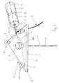
- FIG. 1 is a perspective view of one embodiment of the device according to the invention.
- FIG. 2 is a side view of another embodiment of the device according to the invention.
- FIG. 1 shows an embodiment of the device according to the invention having a body 1 which is shaped in the form of a planar, triangular plate with a top surface 11 and a bottom surface 12 , and a laser 4 which is arranged on centre relative to the ground plan of the plate and emits the laser beam 5 away from the bottom surface 12 into the operating theatre.
- the emitted laser beam 5 has a wave length in the visible range and a geometrical central axis 6 .
- the laser 4 comprises means 20 , preferably realisable in the form of a system of lenses, which are arranged in the area of the bottom surface 12 on the front portion of the laser 4 .
- the body 1 is equally provided with three markers 3 embodied as LEDs placed each in one of the corners of the ground plan of the plate in such a way that the waves 19 embodied in the form of electromagnetic waves are emitted away from the top surface 11 into the operating theatre.
- a handle 8 is fixed on the side of the plate by means of which the body 1 is manually freely movable.
- the handle 8 comprises a cavity 10 wherein two batteries 9 serving as a source of energy for the laser 4 are accommodated.
- the power supply of the laser 4 is realised via a cable 14 which leads from the batteries 9 to the laser 4 and is integrated into the body 1 . It would also be possible to pass the cable 14 on the outside of the body 1 , either along the bottom surface 12 or along the top surface 11 .
- the cables 13 which assure the power supply of the markers 3 , are integrated into the body 1 on part of their lengths.
- the markers 3 embodied as LEDs, are supplied in a centralised way by the navigation system.
- the markers 3 embodied as LEDs are controlled in pulsed mode by the navigation system.
- the temporal correlation between the control pulses and the lighting up of the individual markers 3 enables the positional detection by the navigation system of the surgical instruments provided with markers 3 in the operating theatre.
- the embodiment of the inventive device shown in FIG. 2 differs from the embodiment shown in FIG. 1 only in so far as the body 1 is shaped in the form of a cylindrical or prismatic rod 15 .
- the rod 15 has a central axis 16 , a front end portion 18 , and a rear end portion 17 .
- the laser 4 is integrated into the rod 15 and extends coaxially to the central axis 16 .
- the means 20 permitting the laser beam 5 to be emitted in a geometrically defined position and direction relative to the markers 3 which as in the above example are preferably realised in the form of a system of lenses, are arranged on the front portion of the laser 4 and extend in the direction of the front end portion 18 , so that the geometrical central beam 6 of the laser beam 5 coincides with the central axis 16 .
- the handle 8 with the cavity 10 for receiving two batteries 9 assuring the power supply of the laser 4 is arranged on the rod 15 at a right angle to the central axis 16 .
- the power supply of the laser 4 is realised via the cable 14 which is integrated into the rod 15 and connects the laser 4 to the batteries 9 .
- Three markers 3 are arranged on a straight line coinciding with the central axis 16 , one marker 3 being arranged close to the front end portion 18 , another marker 3 close to the rear end portion 17 , and the third marker 3 being located in an intermediate position on the rod 15 .
- the intermediate marker 3 and the marker 3 arranged close to the rear end portion 17 are separated by a distance A, whereas the intermediate marker 3 and the marker 3 arranged close to the front end portion 18 are separated by a distance B.
- the distances A and B are of unequal length (A ⁇ B) so as to make it possible to determine the direction of emission of the laser beam 5 from the measurement of the positions of the markers 3 by the navigation system.
- the cables 13 which assure the power supply of the markers 3 , are integrated into the body 1 on part of their lengths and lead away from the handle 8 towards the navigation system.
Landscapes
- Health & Medical Sciences (AREA)
- Life Sciences & Earth Sciences (AREA)
- Medical Informatics (AREA)
- Engineering & Computer Science (AREA)
- Heart & Thoracic Surgery (AREA)
- Molecular Biology (AREA)
- Biophysics (AREA)
- Nuclear Medicine, Radiotherapy & Molecular Imaging (AREA)
- Optics & Photonics (AREA)
- Pathology (AREA)
- Radiology & Medical Imaging (AREA)
- Biomedical Technology (AREA)
- Physics & Mathematics (AREA)
- High Energy & Nuclear Physics (AREA)
- Surgery (AREA)
- Animal Behavior & Ethology (AREA)
- General Health & Medical Sciences (AREA)
- Public Health (AREA)
- Veterinary Medicine (AREA)
- Length Measuring Devices By Optical Means (AREA)
- Laser Surgery Devices (AREA)
- Optical Fibers, Optical Fiber Cores, And Optical Fiber Bundles (AREA)
- Lasers (AREA)
- Glass Compositions (AREA)
Applications Claiming Priority (3)
| Application Number | Priority Date | Filing Date | Title |
|---|---|---|---|
| DE20002604U DE20002604U1 (de) | 2000-02-15 | 2000-02-15 | Laserpointer |
| DE20002604.6 | 2000-02-15 | ||
| PCT/CH2000/000668 WO2001060259A1 (de) | 2000-02-15 | 2000-12-18 | Laserpointer |
Publications (2)
| Publication Number | Publication Date |
|---|---|
| US20030012342A1 US20030012342A1 (en) | 2003-01-16 |
| US6855152B2 true US6855152B2 (en) | 2005-02-15 |
Family
ID=7937283
Family Applications (1)
| Application Number | Title | Priority Date | Filing Date |
|---|---|---|---|
| US10/203,996 Expired - Lifetime US6855152B2 (en) | 2000-02-15 | 2000-12-18 | Laser pointer |
Country Status (10)
| Country | Link |
|---|---|
| US (1) | US6855152B2 (de) |
| EP (1) | EP1255487B1 (de) |
| JP (1) | JP2003522984A (de) |
| AT (1) | ATE286365T1 (de) |
| AU (1) | AU770048B2 (de) |
| CA (1) | CA2399804A1 (de) |
| DE (2) | DE20002604U1 (de) |
| ES (1) | ES2231288T3 (de) |
| WO (1) | WO2001060259A1 (de) |
| ZA (1) | ZA200205118B (de) |
Cited By (4)
| Publication number | Priority date | Publication date | Assignee | Title |
|---|---|---|---|---|
| US20050154397A1 (en) * | 2002-03-15 | 2005-07-14 | Alan Ashby | Surgical navigation tool |
| US20070073296A1 (en) * | 2005-09-13 | 2007-03-29 | Panchbhavi Vinod K | Surgical laser guide and method of use |
| US20100220482A1 (en) * | 2010-03-26 | 2010-09-02 | Abbatiello Robert J | Low-divergence light pointer apparatus for use through and against transparent surfaces |
| USD1121826S1 (en) | 2023-08-18 | 2026-04-07 | Stryker European Operations Limited | Surgical tracker |
Families Citing this family (11)
| Publication number | Priority date | Publication date | Assignee | Title |
|---|---|---|---|---|
| CA2637290C (en) * | 2006-01-25 | 2012-08-14 | Orthosoft Ulc | Cas system for condyle measurement |
| US8945147B2 (en) | 2009-04-27 | 2015-02-03 | Smith & Nephew, Inc. | System and method for identifying a landmark |
| RU2413396C1 (ru) * | 2009-12-23 | 2011-02-27 | Виктор Яковлевич Маклашевский | Лазерный центратор для рентгеновского излучателя |
| RU2421948C1 (ru) * | 2010-01-29 | 2011-06-20 | Виктор Яковлевич Маклашевский | Лазерный центратор для рентгеновского излучателя |
| RU2421950C1 (ru) * | 2010-01-29 | 2011-06-20 | Виктор Яковлевич Маклашевский | Лазерный центратор для рентгеновского излучателя |
| RU2421949C1 (ru) * | 2010-01-29 | 2011-06-20 | Виктор Яковлевич Маклашевский | Лазерный центратор для рентгеновского излучателя |
| US9693748B2 (en) * | 2011-07-23 | 2017-07-04 | Broncus Medical Inc. | System and method for automatically determining calibration parameters of a fluoroscope |
| WO2016096675A1 (en) * | 2014-12-16 | 2016-06-23 | Koninklijke Philips N.V. | Pulsed-light emitting marker device |
| EP3691558B1 (de) * | 2017-10-05 | 2025-07-23 | Mobius Imaging LLC | Systeme zur durchführung von computerunterstützter chirurgie |
| JP6974275B2 (ja) * | 2018-08-21 | 2021-12-01 | 株式会社スギノマシン | レーザーポインタ |
| CN114967166B (zh) * | 2022-06-17 | 2023-11-21 | 苏州铸正机器人有限公司 | 一种方向可调指示光单元及具有其的图像校正器 |
Citations (8)
| Publication number | Priority date | Publication date | Assignee | Title |
|---|---|---|---|---|
| US5230623A (en) * | 1991-12-10 | 1993-07-27 | Radionics, Inc. | Operating pointer with interactive computergraphics |
| US5279309A (en) * | 1991-06-13 | 1994-01-18 | International Business Machines Corporation | Signaling device and method for monitoring positions in a surgical operation |
| US5537453A (en) | 1994-11-23 | 1996-07-16 | Williams; Terry N. | Coaxial laser targeting device for use with X-ray equipment |
| US5661775A (en) | 1992-07-01 | 1997-08-26 | Oec, Inc. | X-ray device having a co-axial laser aiming system in an opposed configuration |
| US5676673A (en) * | 1994-09-15 | 1997-10-14 | Visualization Technology, Inc. | Position tracking and imaging system with error detection for use in medical applications |
| US5732703A (en) | 1992-11-30 | 1998-03-31 | The Cleveland Clinic Foundation | Stereotaxy wand and tool guide |
| US6187018B1 (en) * | 1999-10-27 | 2001-02-13 | Z-Kat, Inc. | Auto positioner |
| US6368332B1 (en) * | 1999-03-08 | 2002-04-09 | Septimiu Edmund Salcudean | Motion tracking platform for relative motion cancellation for surgery |
Family Cites Families (7)
| Publication number | Priority date | Publication date | Assignee | Title |
|---|---|---|---|---|
| DE3205404A1 (de) * | 1982-02-16 | 1983-09-15 | Patrick Dr.med. 3590 Bad Wildungen Kluger | Vorrichtung zum kontrollieren des richtungsgenauen fuehrens eines chirurgischen werkzeuges |
| DE3717871C3 (de) * | 1987-05-27 | 1995-05-04 | Georg Prof Dr Schloendorff | Verfahren und Vorrichtung zum reproduzierbaren optischen Darstellen eines chirururgischen Eingriffes |
| EP0553246B1 (de) | 1990-10-19 | 2000-09-13 | St. Louis University | Lokalisierungssystem für eine chirurgische sonde zur anwendung am kopf |
| DE4225112C1 (de) * | 1992-07-30 | 1993-12-09 | Bodenseewerk Geraetetech | Einrichtung zum Messen der Position eines Instruments relativ zu einem Behandlungsobjekt |
| DE19502356A1 (de) * | 1995-01-26 | 1996-08-08 | Laser Applikationan Gmbh | Zielvorrichtung für das geradlinige Einführen eines Instruments in einen menschlichen Körper |
| JP3792257B2 (ja) * | 1996-04-29 | 2006-07-05 | ノーザン・デジタル・インコーポレーテッド | 画像誘導手術システム |
| DE19801446A1 (de) * | 1997-03-13 | 1998-09-17 | Siemens Ag | Vorrichtung und Markierung des Führungsweges eines Instruments |
-
2000
- 2000-02-15 DE DE20002604U patent/DE20002604U1/de not_active Expired - Lifetime
- 2000-12-18 DE DE50009176T patent/DE50009176D1/de not_active Expired - Lifetime
- 2000-12-18 CA CA002399804A patent/CA2399804A1/en not_active Abandoned
- 2000-12-18 ES ES00979323T patent/ES2231288T3/es not_active Expired - Lifetime
- 2000-12-18 AT AT00979323T patent/ATE286365T1/de active
- 2000-12-18 WO PCT/CH2000/000668 patent/WO2001060259A1/de not_active Ceased
- 2000-12-18 EP EP00979323A patent/EP1255487B1/de not_active Expired - Lifetime
- 2000-12-18 JP JP2001559360A patent/JP2003522984A/ja active Pending
- 2000-12-18 US US10/203,996 patent/US6855152B2/en not_active Expired - Lifetime
- 2000-12-18 AU AU16864/01A patent/AU770048B2/en not_active Ceased
-
2002
- 2002-06-25 ZA ZA200205118A patent/ZA200205118B/xx unknown
Patent Citations (8)
| Publication number | Priority date | Publication date | Assignee | Title |
|---|---|---|---|---|
| US5279309A (en) * | 1991-06-13 | 1994-01-18 | International Business Machines Corporation | Signaling device and method for monitoring positions in a surgical operation |
| US5230623A (en) * | 1991-12-10 | 1993-07-27 | Radionics, Inc. | Operating pointer with interactive computergraphics |
| US5661775A (en) | 1992-07-01 | 1997-08-26 | Oec, Inc. | X-ray device having a co-axial laser aiming system in an opposed configuration |
| US5732703A (en) | 1992-11-30 | 1998-03-31 | The Cleveland Clinic Foundation | Stereotaxy wand and tool guide |
| US5676673A (en) * | 1994-09-15 | 1997-10-14 | Visualization Technology, Inc. | Position tracking and imaging system with error detection for use in medical applications |
| US5537453A (en) | 1994-11-23 | 1996-07-16 | Williams; Terry N. | Coaxial laser targeting device for use with X-ray equipment |
| US6368332B1 (en) * | 1999-03-08 | 2002-04-09 | Septimiu Edmund Salcudean | Motion tracking platform for relative motion cancellation for surgery |
| US6187018B1 (en) * | 1999-10-27 | 2001-02-13 | Z-Kat, Inc. | Auto positioner |
Cited By (6)
| Publication number | Priority date | Publication date | Assignee | Title |
|---|---|---|---|---|
| US20050154397A1 (en) * | 2002-03-15 | 2005-07-14 | Alan Ashby | Surgical navigation tool |
| US20070073296A1 (en) * | 2005-09-13 | 2007-03-29 | Panchbhavi Vinod K | Surgical laser guide and method of use |
| US8388627B2 (en) | 2005-09-13 | 2013-03-05 | Board Of Regents, The University Of Texas System | Surgical laser guide and method of use |
| US20100220482A1 (en) * | 2010-03-26 | 2010-09-02 | Abbatiello Robert J | Low-divergence light pointer apparatus for use through and against transparent surfaces |
| US8376586B2 (en) | 2010-03-26 | 2013-02-19 | Robert J. Abbatiello | Low-divergence light pointer apparatus for use through and against transparent surfaces |
| USD1121826S1 (en) | 2023-08-18 | 2026-04-07 | Stryker European Operations Limited | Surgical tracker |
Also Published As
| Publication number | Publication date |
|---|---|
| ATE286365T1 (de) | 2005-01-15 |
| AU770048B2 (en) | 2004-02-12 |
| JP2003522984A (ja) | 2003-07-29 |
| ES2231288T3 (es) | 2005-05-16 |
| WO2001060259A1 (de) | 2001-08-23 |
| US20030012342A1 (en) | 2003-01-16 |
| CA2399804A1 (en) | 2001-08-23 |
| EP1255487B1 (de) | 2005-01-05 |
| EP1255487A1 (de) | 2002-11-13 |
| ZA200205118B (en) | 2003-03-26 |
| DE50009176D1 (de) | 2005-02-10 |
| AU1686401A (en) | 2001-08-27 |
| DE20002604U1 (de) | 2001-06-21 |
Similar Documents
| Publication | Publication Date | Title |
|---|---|---|
| US6478802B2 (en) | Method and apparatus for display of an image guided drill bit | |
| AU770048B2 (en) | Laser pointer | |
| US8224423B2 (en) | Means of tracking movement of bodies during medical treatment | |
| US6887245B2 (en) | Surgical drill for use with a computer assisted surgery system | |
| JP5741885B2 (ja) | 物体の空間位置そして/または空間方位の非接触決定及び測定用システムと方法、特に医療器具に関するパターン又は構造体を含む特に医療器具の較正及び試験方法 | |
| AU742207B2 (en) | Fiducial matching by means of fiducial screws | |
| US6428547B1 (en) | Detection of the shape of treatment devices | |
| CN101410070B (zh) | 图像引导外科系统 | |
| US7029477B2 (en) | Surgical instrument and positioning method | |
| US5212720A (en) | Dual radiation targeting system | |
| US7458977B2 (en) | Surgical navigation instrument useful in marking anatomical structures | |
| EP1219259B1 (de) | Anordnung zur Bestimmung der gegenseitigen Lage von Körpern | |
| US20070299334A1 (en) | Medical instrument with a touch-sensitive tip and light emission source | |
| US20110190637A1 (en) | Medical measuring system, method for surgical intervention as well as use of a medical measuring system | |
| US20150117601A1 (en) | X-ray source with module and detector for optical radiation | |
| JP2002516690A (ja) | 赤外線を用いた手術場所を位置付けする装置および方法 | |
| JP2002035007A (ja) | 光ポイントの照射による医療用ナビゲーションシステムにおける患者または患者の身体部分の参照または記録 | |
| KR20000070400A (ko) | 에너지를 사용하여 안내하는 장치 및 방법 | |
| JPH09507130A (ja) | 顕微鏡外科手術用をはじめとする、光学的指示装置 | |
| ES2357837T3 (es) | Dispositivo para la determinación de los agujeros de un clavo intramedular. | |
| JP7029932B2 (ja) | 器具類の深さを測定するためのシステム及び方法 | |
| US6895266B1 (en) | Laser light emitter surgical site locating device and method | |
| US5792215A (en) | Laser integrated targeting and entry system and method | |
| GB2443432A (en) | Optical guidance apparatus for x-ray imaging device | |
| MXPA00011403A (en) | Fiducial matching by means of fiducial screws |
Legal Events
| Date | Code | Title | Description |
|---|---|---|---|
| AS | Assignment |
Owner name: AO-ENTWICKLUNGSINSTITUT DAVOS, SWITZERLAND Free format text: ASSIGNMENT OF ASSIGNORS INTEREST;ASSIGNORS:SUHM, NORBERT;MESSMER, PETER;REGAZZONI, PIETRO;AND OTHERS;REEL/FRAME:013285/0180 Effective date: 20020812 |
|
| AS | Assignment |
Owner name: SYNTHES AG CHUR, SWITZERLAND Free format text: ASSIGNMENT OF ASSIGNORS INTEREST;ASSIGNOR:AO-ENTWICKLUNGSINSTITUT DAVOS;REEL/FRAME:014249/0458 Effective date: 20031218 |
|
| STCF | Information on status: patent grant |
Free format text: PATENTED CASE |
|
| AS | Assignment |
Owner name: AO TECHNOLOGY AG, SWITZERLAND Free format text: CHANGE OF NAME;ASSIGNOR:SYNTHES AG CHUR;REEL/FRAME:018923/0236 Effective date: 20070117 |
|
| FEPP | Fee payment procedure |
Free format text: PAYER NUMBER DE-ASSIGNED (ORIGINAL EVENT CODE: RMPN); ENTITY STATUS OF PATENT OWNER: LARGE ENTITY |
|
| FPAY | Fee payment |
Year of fee payment: 4 |
|
| FPAY | Fee payment |
Year of fee payment: 8 |
|
| FPAY | Fee payment |
Year of fee payment: 12 |