US6830447B2 - Valve gate assembly for injection molding - Google Patents
Valve gate assembly for injection molding Download PDFInfo
- Publication number
- US6830447B2 US6830447B2 US09/944,109 US94410901A US6830447B2 US 6830447 B2 US6830447 B2 US 6830447B2 US 94410901 A US94410901 A US 94410901A US 6830447 B2 US6830447 B2 US 6830447B2
- Authority
- US
- United States
- Prior art keywords
- valve pin
- gate
- nozzle
- head portion
- section
- Prior art date
- Legal status (The legal status is an assumption and is not a legal conclusion. Google has not performed a legal analysis and makes no representation as to the accuracy of the status listed.)
- Expired - Lifetime
Links
Images


Classifications
-
- B—PERFORMING OPERATIONS; TRANSPORTING
- B29—WORKING OF PLASTICS; WORKING OF SUBSTANCES IN A PLASTIC STATE IN GENERAL
- B29C—SHAPING OR JOINING OF PLASTICS; SHAPING OF MATERIAL IN A PLASTIC STATE, NOT OTHERWISE PROVIDED FOR; AFTER-TREATMENT OF THE SHAPED PRODUCTS, e.g. REPAIRING
- B29C45/00—Injection moulding, i.e. forcing the required volume of moulding material through a nozzle into a closed mould; Apparatus therefor
- B29C45/17—Component parts, details or accessories; Auxiliary operations
- B29C45/26—Moulds
- B29C45/27—Sprue channels ; Runner channels or runner nozzles
- B29C45/28—Closure devices therefor
- B29C45/2896—Closure devices therefor extending in or through the mould cavity, e.g. valves mounted opposite the sprue channel
-
- B—PERFORMING OPERATIONS; TRANSPORTING
- B29—WORKING OF PLASTICS; WORKING OF SUBSTANCES IN A PLASTIC STATE IN GENERAL
- B29C—SHAPING OR JOINING OF PLASTICS; SHAPING OF MATERIAL IN A PLASTIC STATE, NOT OTHERWISE PROVIDED FOR; AFTER-TREATMENT OF THE SHAPED PRODUCTS, e.g. REPAIRING
- B29C45/00—Injection moulding, i.e. forcing the required volume of moulding material through a nozzle into a closed mould; Apparatus therefor
- B29C45/17—Component parts, details or accessories; Auxiliary operations
- B29C45/26—Moulds
- B29C45/27—Sprue channels ; Runner channels or runner nozzles
- B29C45/28—Closure devices therefor
- B29C45/2806—Closure devices therefor consisting of needle valve systems
- B29C2045/2882—Closure devices therefor consisting of needle valve systems closing by a movement in the counterflow direction
-
- B—PERFORMING OPERATIONS; TRANSPORTING
- B29—WORKING OF PLASTICS; WORKING OF SUBSTANCES IN A PLASTIC STATE IN GENERAL
- B29L—INDEXING SCHEME ASSOCIATED WITH SUBCLASS B29C, RELATING TO PARTICULAR ARTICLES
- B29L2017/00—Carriers for sound or information
- B29L2017/001—Carriers of records containing fine grooves or impressions, e.g. disc records for needle playback, cylinder records
- B29L2017/003—Records or discs
- B29L2017/005—CD''s, DVD''s
Definitions
- This invention relates generally to the injection molding of articles with an aperture therein and, more particularly, to an improved gating apparatus for injection molding articles having large apertures.
- Injection molding can be used advantageously to mold plastic articles of all shapes and description.
- articles include those having an aperture therethrough, typically centrally located, such as in an audio compact disc or a lamp shade, or the like.
- Various apparatus are known in the art for accomplishing the molding of such articles, as shown in U.S. Pat. No. 4,368,028 to Grish et al., U.S. Pat. No. 4,530,654 to Rose and U.S. Pat. No. 5,423,672 to Gordon and Japanese Patent No. JP10-16005, each of which is incorporated herein by reference.
- These references disclose an injection molding apparatus having a nozzle with a central valve pin therein, creating an annular passage for melt to flow therearound to a gated tip.
- the valve pin permits the flow of melt to be positively selectively controlled and, when extended from the nozzle, also causes an annular ring ‘gate’ form between the pin and the nozzle tip, thereby permitting an annular article to be formed having a central aperture therethrough.
- a possible solution to the problem of reducing melt volume in the nozzle is to increase the pin diameter correspondingly to reduce the overall volume of melt in the nozzle. If the pin diameter is so increased, however, the melt is exposed to an increased overall surface area in the nozzle which results in increased pressure losses in the runner system.
- the present invention provides an injection molding apparatus for forming articles having a hole, comprising:
- At least one injection molding nozzle having an annular gate, the nozzle connectable to a source of molten material and capable of feeding molten material from the source to the gate through at least one melt channel through the nozzle, the gate communicating with the mold cavity and having a cross-section that is wider than the cross-section of the melt channel;
- valve pin disposed interior of the melt channel and the gate, the valve pin defining an unrestricted melt flow passage through the melt channel around and along the valve pin, the valve pin moveable between a closed position in which the valve pin substantially contacts the gate sufficiently to stop the flow of molten material through the gate, and an open position in which molten material can flow unrestricted to the gate.
- the present invention provides an injection molding apparatus for forming articles having a hole, comprising:
- At least one injection molding nozzle having an annular gate, the nozzle connectable to a source of molten material and capable of feeding molten material from the source to the gate through at least one melt channel through the nozzle, the gate communicating with the mold cavity and having a cross-section that is wider than the cross-section of the melt channel;
- valve pin disposed interior of the melt channel and the gate, the valve pin defining an unobstructed melt flow passage through the melt channel around and along the valve pin, the valve pin moveable between a closed position in which the valve pin substantially contacts the gate sufficiently to stop the flow of molten material through the gate, and an open position in which molten material can flow unobstructed to the gate.
- the present invention provides an injection molding apparatus for forming articles having a hole, comprising:
- a mold having a cavity plate and an adjacent core which enclose a mold cavity therebetween;
- an injection molding nozzle having a melt channel therethrough, the melt channel communicating with the mold cavity through an annular gate at the tip of the nozzle;
- valve pin disposed interior of the melt channel, the valve pin and the melt channel defining a melt flow passage around and along the valve pin, the valve pin having a head portion adjacent the nozzle tip and a stem portion remote from the nozzle tip, the head portion having a wider cross-section than the stem portion;
- an actuator operatively linked to the stem portion of the valve pin to move the valve pin between an open position with its head portion adjacent the gate in which molten material can flow through the gate into the mold cavity, and a closed position with its head portion blocking the gate to seal the communication between the nozzle and the mold cavity.
- the present invention provides an injection molding system for forming articles having a hole, comprising:
- a mold cavity plate and a plurality of mold cores defining with the mold cavity plate a plurality of mold cavities
- melt distribution manifold for delivering molten material to the mold cavities
- each nozzle having a melt channel therethrough, the melt channel communicating with its respective mold cavity through an annular gate at the tip of the nozzle;
- each of the nozzles having a valve pin disposed interior of the melt channel, the valve pin and the melt channel defining a melt flow passage around and along the valve pin, the valve pin having a head portion adjacent the nozzle tip and a stem portion remote from the nozzle tip, the head portion having a wider cross-section than the stem portion;
- actuating means operatively linked to the stem portion of each of the valve pins to move each valve pin between an open position with its head portion adjacent the gate in which molten material can flow through the gate into the mold cavity, and a closed position with its head portion blocking the gate to seal the communication between the nozzle and the mold cavity.
- the valve pin preferably has a smooth transition portion between the stem portion and the head portion.
- the distal end of the head portion may have a guide portion which engages the core for guiding the valve pin between its open and closed positions.
- a core sleeve may be provided for engaging the perimeter of the head portion of the valve pin. Further, the perimeter of the head portion of the valve pin may form part of the surface of the core when the valve pin is in its closed position to at least partly define and form the hole.
- the shape of the annular gate (and the parts that form the gate) may be chosen to form a hole of any desired shape in the articles to be molded.
- the gate cross-section may be circular, oval, square, rectangular, or irregular.
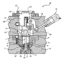
- FIG. 1 is a sectional side view of an injection molding apparatus according to the present invention
- FIG. 2 is an enlarged partial view of the apparatus of FIG. 1 at circle A, the apparatus being shown in the “closed” position;
- FIG. 3 is an enlarged view similar to FIG. 2, showing the apparatus in an intermediate position
- FIG. 4 is an enlarged view similar to FIG. 2, showing the apparatus in the “open” position;
- FIG. 5 is a sectional side view of a core and molded article, namely a lamp shade, in accordance with the present invention
- FIG. 6 is a partial sectional view of a multi-cavity injection molding apparatus according to the invention.
- FIG. 7 is a partial sectional view of another multi-cavity injection molding apparatus according to the invention.
- FIG. 8 is a plan view of a circular hole that can be molded into a product using apparatus according to the invention.
- FIG. 9 is a plan view of an oval hole that can be molded into a product using apparatus according to the invention.
- FIG. 10 is a plan view of a square hole that can be molded into a product using apparatus according to the invention.
- FIG. 11 is a plan view of a rectangular hole that can be molded into a product using apparatus according to the invention.
- FIG. 12 is a plan view of an irregular hole that can be molded into a product using apparatus according to the invention.
- Apparatus M comprises a nozzle mold plate 20 and a cavity plate 13 cooperating with a mold core 10 along a parting line PL to form a mold cavity 11 therebetween.
- An injection molding machine (not shown) has an injection nozzle (not shown) which communicates with a heated runner system 30 via a sprue bushing 32 to provide molten plastic therethrough, under pressure.
- a locating ring 21 is provided to position the molding machine.
- Runner system 30 communicates through an inlet sleeve or body 17 with a melt channel 12 centrally located in an injection nozzle 7 .
- Injection nozzle 7 has a nozzle head 15 and is positioned in a nozzle plate 6 positioned substantially in cavity plate 13 .
- Runner system 30 is maintained at a desired operating temperature by inlet body heater elements 16 , nozzle heater elements 14 and a thermocouple 9 communicating with a suitable control system (not shown), as is well known in the art.
- Centrally disposed in melt channel 12 of nozzle 7 is a valve pin 1 which is axially movable in nozzle 7 , for reasons described in more detail below, by the cooperation of an activating cylinder 19 (which may be pneumatic or hydraulic, as is well known in the art), and a rack and pinion motion transfer gear train 18 .
- an activating cylinder 19 which may be pneumatic or hydraulic, as is well known in the art
- valve pin 1 has a stem 1 ′, a neck 4 , a plate or head 2 and a guiding lug or spigot 3 .
- a removable nozzle tip 8 and a nozzle plate 6 cooperate with neck 4 and head 2 to selectively connect melt channel 12 with mold cavity 11 depending on the position of valve pin 1 , as will be described in more detail below.
- a spigot notch or bore 5 is provided in core 10 for receiving and guiding valve spigot 3 .
- Spigot bore 5 has a shoulder 34 for receiving valve head 2 , and a core sleeve space 23 is present between shoulder 34 and head 2 when valve pin 1 is in any position other than the “open” position, as will be described below.
- a core sleeve 22 surrounds core sleeve space 23 to prevent melt from penetrating therein.
- Nozzle tip 8 has an enlarged opening 36 in the mold end thereof which cooperates with valve pin 1 to create a nozzle tip gate 24 therebetween.
- Melt channel 12 communicates with opening 36 via a substantially smooth transition zone 38 .
- Valve pin 1 , valve stem 1 ′, valve head 2 , melt channel 12 , transition 38 and opening 36 are substantially circular in cross-section so as to define an annular melt passage (between valve pin 1 and nozzle 7 ) and give gate 24 an annular entry into mold cavity 11 .
- Valve stem 1 ′ has an outside diameter D 1 and head 2 has an outside diameter D 2
- melt channel 12 has a diameter of M 1 and opening 36 has an inside diameter M 2 .
- head 2 diameter D 2 is slightly less than opening 36 diameter M 2 to permit head 2 to be inserted into opening 36 to close gate 24 , as will be described in more detail below.
- head 2 When in the “closed” position, as shown in FIG. 2, head 2 is positioned so as to substantially contact tip 8 at opening 36 to close gate 24 . Pressurized melt in runner system 30 is thus prevented from entering mold cavity 11 .
- core sleeve space 23 has a height of ⁇ 2 , as shown, and part of the outer annular surface of head 2 forms part of the core surface that will shape the hole in the molded part.
- cylinder 19 may be selectively actuated and controlled by an appropriate system (not shown) to activate rack and pinion gear 18 to effect an axial movement of valve pin 1 within nozzle 7 . From the “closed” position (FIG. 2 ), cylinder 19 , when driven, advances valve pin 1 axially in nozzle 7 through an intermediate position (FIG. 3) to a fully “open” position (FIG. 4 ).
- valve pin 1 when valve pin 1 is in the “open” position, valve pin 1 has moved axially away from nozzle tip 8 , so that gate 24 is opened between head 2 and opening 36 .
- Gate 24 thus provides a passage for heated melt to pass from melt channel 12 in nozzle 7 and into cavity 11 , in response to pressure from the injection molding machine (not shown).
- core sleeve space 23 In the intermediate position (FIG. 3 ), core sleeve space 23 has a height of ⁇ 1 , but in the fully “open” position, there is essentially no core sleeve space at 23 ′ (see FIG. 4 ).
- runner system 30 is annular, unobstructed and continuous throughout melt channel 12 , gate 24 and ultimately mold cavity 11 .
- the melt flow path around and along valve pin 1 is unrestricted substantially up to the gate 24 , i.e., the cross-sectional area of this portion of the melt flow path does not appreciably diminish substantially up to the gate.
- This free-flow is advantageous because it assists in reducing pressure losses in the system and permits resin colour changes to be achieved more quickly in the apparatus.
- the enlarged opening 36 and the cooperation of transition zone 38 and valve neck 4 advantageously permit a larger aperture ring gate 24 to be achieved than is possible with the prior art and without the need for the spreading or distribution means of the prior art, such as those shown variously in U.S. Pat. No. 4,340,353 to Mayer, U.S. Pat. No. 5,324,190 to Frei, U.S. Pat. No. 5,460,763 to Asai, U.S. Pat. No. 4,394,117 to Taylor, U.S. Pat. No. 5,783,234 to Teng and U.S. Pat. No. 5,840,231 to Teng, each of which is incorporated herein by reference.
- Diameter M 2 of opening 36 is chosen according to the particular application, as will be understood by one skilled in the art, and will be larger than diameter M 1 of melt bore 12 in order to achieve the benefit of an ability to mold larger aperture parts according to the present invention. As shown in the Figures, a diameter M 2 that is much larger than M 1 is preferred, and a diameter M 2 of roughly the diameter of tip 8 , or greater, is yet more preferable.
- valve pin 1 may be achieved by other known means. See, e.g., U.S. Pat. No. 4,053,271 to Gellert; U.S. Pat. No. 5,916,605 to Swenson; U.S. Pat. No. 5,948,450 to Swenson; U.S. Pat. No. 5,984,661 to Vorkoper; U.S. Pat. No. 6,159,000 to Puri; and U.S. Pat. No. 6,086,357 to Steil, all of which are incorporated herein by reference.
- melt typically flows through one or more melt distribution manifolds and is injected into each cavity through a respective nozzle, the valve pins of the nozzles being actuated simultaneously, as is well-known in the art. See, e.g., the camming mechanisms disclosed in U.S. Pat. No. 4,212,627 to Gellert, and U.S. Pat. No. 6,113,381 to Gellert, both of which are incorporated herein by reference.
- FIG. 6 shows the multi-cavity arrangement with common valve pin actuating mechanism of the latter patent in which nozzles according to the invention can be used.
- multiple nozzles 40 are seated in a retainer plate 42 and have commonly actuated valve pins 44 .
- a melt distribution manifold 46 feeds melt to the nozzles via melt passages 48 .
- FIG. 7 shows the fluid drive disclosed in this patent, which can be used in conjunction with nozzles according to the invention.
- each nozzle 50 is seated in a plate 52 and has a valve pin 54 actuated by a fluid-driven piston 56 that reciprocates within a cylinder 58 .
- the piston and cylinder drive 56 , 58 are coaxial with the valve pin 54 .
- Melt is fed to each nozzle laterally from a melt distribution manifold 60 via melt passages 62 .
- valve head 2 , surrounding opening 36 and core sleeve 22 have circular cross-sections and form a ring-shaped gate 24 , resulting in a molded part that has a circular hole as shown in FIG. 8 .
- apparatus according to the invention can be used to make parts having large holes of any other regular shape, e.g., oval (FIG. 9 ), square (FIG. 10 ), rectangular (FIG. 11 ), etc., or holes of any irregular shape (see, e.g., FIG. 12 ), by using mating parts of selected shape.
- the term “annular” as applied to the gate and the mating parts that define the gate are not limited to circular shapes, and can encompass virtually any closed shape.
Landscapes
- Engineering & Computer Science (AREA)
- Manufacturing & Machinery (AREA)
- Mechanical Engineering (AREA)
- Moulds For Moulding Plastics Or The Like (AREA)
Applications Claiming Priority (3)
| Application Number | Priority Date | Filing Date | Title |
|---|---|---|---|
| CA2,317,779 | 2000-09-06 | ||
| CA2317779 | 2000-09-06 | ||
| CA002317779A CA2317779A1 (en) | 2000-09-06 | 2000-09-06 | Valve gate assembly for injection molding |
Publications (2)
| Publication Number | Publication Date |
|---|---|
| US20020028266A1 US20020028266A1 (en) | 2002-03-07 |
| US6830447B2 true US6830447B2 (en) | 2004-12-14 |
Family
ID=4167047
Family Applications (1)
| Application Number | Title | Priority Date | Filing Date |
|---|---|---|---|
| US09/944,109 Expired - Lifetime US6830447B2 (en) | 2000-09-06 | 2001-09-04 | Valve gate assembly for injection molding |
Country Status (6)
| Country | Link |
|---|---|
| US (1) | US6830447B2 (de) |
| JP (1) | JP2002127202A (de) |
| CA (1) | CA2317779A1 (de) |
| DE (1) | DE10143737A1 (de) |
| LU (1) | LU90822B1 (de) |
| NL (1) | NL1018890C2 (de) |
Cited By (3)
| Publication number | Priority date | Publication date | Assignee | Title |
|---|---|---|---|---|
| US20050046082A1 (en) * | 2003-08-29 | 2005-03-03 | Mold-Masters Limited | Guided valve pin for an injection molding apparatus |
| US20090098233A1 (en) * | 2007-10-12 | 2009-04-16 | Mold-Masters (2007) Limited | Injection Molding Actuator Position Sensing |
| US20150158224A1 (en) * | 2013-12-09 | 2015-06-11 | Jtekt Corporation | Ring valve gate mold device |
Families Citing this family (4)
| Publication number | Priority date | Publication date | Assignee | Title |
|---|---|---|---|---|
| SE524000C2 (sv) * | 2001-10-10 | 2004-06-15 | Nolato Ab | Back, och backmekanism vid ett formsprutningsverktyg |
| US20080224353A1 (en) * | 2007-03-14 | 2008-09-18 | Husky Injection Molding Systems Ltd. | Hydraulic Valve of Molding System |
| CN103252618A (zh) * | 2012-02-15 | 2013-08-21 | 上海占瑞模具设备有限公司 | 热流道紧固套环安装治具及其使用方法 |
| CH706993A1 (de) * | 2012-09-19 | 2014-03-31 | Alpla Werke | Spritzgiessvorrichtung und Verfahren zur Herstellung eines Tubenkopfes, sowie Tubenkopf. |
Citations (22)
| Publication number | Priority date | Publication date | Assignee | Title |
|---|---|---|---|---|
| US4053271A (en) | 1976-02-04 | 1977-10-11 | Gellert Jobst U | Valve-gated injection molding mechanism |
| US4212627A (en) | 1978-12-08 | 1980-07-15 | Gellert Jobst U | Injection molding valve pin actuator mechanism |
| US4330258A (en) * | 1980-10-15 | 1982-05-18 | Gellert Jobst U | Injection molding mechanical double acting valve pin actuator |
| US4340353A (en) | 1980-10-31 | 1982-07-20 | Discovision Associates | Hot sprue valve assembly for an injection molding machine |
| US4368028A (en) | 1981-02-02 | 1983-01-11 | Grish Anthony J | Annular flow plastic extrusion nozzle or gate |
| US4394117A (en) | 1981-06-10 | 1983-07-19 | Discovision Associates | Hot sprue sleeve valve assembly for an injection molding machine |
| US4530654A (en) | 1984-05-29 | 1985-07-23 | Mold-Masters Limited | Injection molding peripheral opening core ring gate |
| US5324190A (en) | 1990-11-09 | 1994-06-28 | Gpt Axxicon B.V. | Injection mould for manufacturing disc-shaped plastic articles |
| US5423672A (en) | 1993-02-25 | 1995-06-13 | Sony Electronics Inc. | Molding device having a ring-gating and hole forming valve gate pin |
| US5443381A (en) | 1994-07-18 | 1995-08-22 | Gellert; Jobst U. | Injection molding one-piece insert having cooling chamber with radial rib portions |
| US5460763A (en) * | 1993-12-24 | 1995-10-24 | Kabushiki Kaisha Meiki Seisakusho | Sprueless disc mold and disc molding method thereof |
| US5695793A (en) * | 1996-05-02 | 1997-12-09 | Mold-Masters Limited | Injection molding valve member with head and neck portions |
| JPH1016005A (ja) | 1996-06-27 | 1998-01-20 | Victor Co Of Japan Ltd | 射出成形機のバルブゲート装置 |
| US5783234A (en) | 1996-07-25 | 1998-07-21 | Husky Injection Molding Systems Ltd. | Hot runner valve gate for eliminating unidirectional molecular orientation and weld lines from solidified resin used for forming molded articles |
| US5785915A (en) | 1996-09-13 | 1998-07-28 | Osuna-Diaz; Jesus M. | Injection molding with annular gate and sleeve shutoff valve |
| US5840231A (en) | 1997-08-14 | 1998-11-24 | Husky Injection Molding Systems Ltd. | Valve gate assembly |
| US5916605A (en) | 1996-09-27 | 1999-06-29 | Dynisco Hotrunners, Inc. | Valve actuated injection molding apparatus |
| WO1999046108A1 (en) * | 1998-03-13 | 1999-09-16 | Axxicon Moulds Eindhoven B.V. | Injection mould for disc-like plastic objects and multiple injection moulding unit |
| US5984661A (en) | 1996-09-30 | 1999-11-16 | Eurotool Beheer B.V. | Valve-gated injection moulding device |
| US6086357A (en) | 1998-12-21 | 2000-07-11 | D-M-E Company | Actuator for an injection molding valve gate |
| US6113381A (en) | 1999-02-08 | 2000-09-05 | Mold-Masters Limited | Injection molding valve member actuating mechanism |
| US6159000A (en) | 1999-03-12 | 2000-12-12 | Husky Injection Molding Systems Ltd. | Valve gated injection molding device |
Family Cites Families (14)
| Publication number | Priority date | Publication date | Assignee | Title |
|---|---|---|---|---|
| JPS5561438A (en) * | 1978-11-02 | 1980-05-09 | Hokoku Jushi Kogyo Kk | Hot runner system injection molding method and nozzle used for the said injection molding |
| JPS585238A (ja) * | 1981-07-01 | 1983-01-12 | Asahi Chem Ind Co Ltd | フアンゲ−ト型ホツトランナ金型 |
| JP2683949B2 (ja) * | 1990-07-20 | 1997-12-03 | 株式会社名機製作所 | スプルレスディスク金型 |
| JPH0710547B2 (ja) * | 1990-11-09 | 1995-02-08 | プラストロン株式会社 | 内外加熱ディスクゲート装置 |
| DE69412704T2 (de) * | 1993-06-10 | 1999-02-04 | Idemitsu Petrochemical Co., Ltd., Tokio/Tokyo | Spritzgiessform |
| JP2873786B2 (ja) * | 1994-11-14 | 1999-03-24 | 株式会社名機製作所 | スプルーレスディスク金型およびそのディスク成形方法 |
| JP2973158B2 (ja) * | 1993-12-24 | 1999-11-08 | 株式会社名機製作所 | スプルーレスディスク金型 |
| JP2975862B2 (ja) * | 1994-12-27 | 1999-11-10 | 三洋電機株式会社 | ディスクの製造装置 |
| JP3213932B2 (ja) * | 1996-03-29 | 2001-10-02 | 三菱マテリアル株式会社 | 射出成形方法 |
| JP4136023B2 (ja) * | 1996-11-27 | 2008-08-20 | 株式会社日本製鋼所 | 光ディスク成形装置 |
| CA2203741C (en) * | 1997-04-25 | 2007-02-20 | Mold-Masters Limited | Injection molding apparatus with a one-piece gate insert locating a cylindrical valve member |
| JPH11170308A (ja) * | 1997-12-05 | 1999-06-29 | Victor Co Of Japan Ltd | 射出成形機のバルブゲート装置 |
| NL1010868C2 (nl) * | 1998-12-22 | 2000-06-27 | Axxicon Moulds Eindhoven Bv | Spuitgietmatrijs voor schijfvormige kunststof voorwerpen en spuitgieteenheid. |
| JP2002011763A (ja) * | 2000-06-28 | 2002-01-15 | Mitsubishi Materials Corp | 射出成形用金型装置 |
-
2000
- 2000-09-06 CA CA002317779A patent/CA2317779A1/en not_active Abandoned
-
2001
- 2001-08-30 LU LU90822A patent/LU90822B1/fr active
- 2001-09-04 US US09/944,109 patent/US6830447B2/en not_active Expired - Lifetime
- 2001-09-05 NL NL1018890A patent/NL1018890C2/nl not_active IP Right Cessation
- 2001-09-06 JP JP2001270861A patent/JP2002127202A/ja active Pending
- 2001-09-06 DE DE10143737A patent/DE10143737A1/de not_active Ceased
Patent Citations (23)
| Publication number | Priority date | Publication date | Assignee | Title |
|---|---|---|---|---|
| US4053271A (en) | 1976-02-04 | 1977-10-11 | Gellert Jobst U | Valve-gated injection molding mechanism |
| US4212627A (en) | 1978-12-08 | 1980-07-15 | Gellert Jobst U | Injection molding valve pin actuator mechanism |
| US4330258A (en) * | 1980-10-15 | 1982-05-18 | Gellert Jobst U | Injection molding mechanical double acting valve pin actuator |
| US4340353A (en) | 1980-10-31 | 1982-07-20 | Discovision Associates | Hot sprue valve assembly for an injection molding machine |
| US4368028A (en) | 1981-02-02 | 1983-01-11 | Grish Anthony J | Annular flow plastic extrusion nozzle or gate |
| US4394117A (en) | 1981-06-10 | 1983-07-19 | Discovision Associates | Hot sprue sleeve valve assembly for an injection molding machine |
| US4530654A (en) | 1984-05-29 | 1985-07-23 | Mold-Masters Limited | Injection molding peripheral opening core ring gate |
| US5324190A (en) | 1990-11-09 | 1994-06-28 | Gpt Axxicon B.V. | Injection mould for manufacturing disc-shaped plastic articles |
| US5423672A (en) | 1993-02-25 | 1995-06-13 | Sony Electronics Inc. | Molding device having a ring-gating and hole forming valve gate pin |
| US5460763A (en) * | 1993-12-24 | 1995-10-24 | Kabushiki Kaisha Meiki Seisakusho | Sprueless disc mold and disc molding method thereof |
| US5443381A (en) | 1994-07-18 | 1995-08-22 | Gellert; Jobst U. | Injection molding one-piece insert having cooling chamber with radial rib portions |
| US5695793A (en) * | 1996-05-02 | 1997-12-09 | Mold-Masters Limited | Injection molding valve member with head and neck portions |
| JPH1016005A (ja) | 1996-06-27 | 1998-01-20 | Victor Co Of Japan Ltd | 射出成形機のバルブゲート装置 |
| US5783234A (en) | 1996-07-25 | 1998-07-21 | Husky Injection Molding Systems Ltd. | Hot runner valve gate for eliminating unidirectional molecular orientation and weld lines from solidified resin used for forming molded articles |
| US5785915A (en) | 1996-09-13 | 1998-07-28 | Osuna-Diaz; Jesus M. | Injection molding with annular gate and sleeve shutoff valve |
| US5916605A (en) | 1996-09-27 | 1999-06-29 | Dynisco Hotrunners, Inc. | Valve actuated injection molding apparatus |
| US5948450A (en) | 1996-09-27 | 1999-09-07 | Dynisco Hotrunners, Inc. | Valve actuated injection molding apparatus |
| US5984661A (en) | 1996-09-30 | 1999-11-16 | Eurotool Beheer B.V. | Valve-gated injection moulding device |
| US5840231A (en) | 1997-08-14 | 1998-11-24 | Husky Injection Molding Systems Ltd. | Valve gate assembly |
| WO1999046108A1 (en) * | 1998-03-13 | 1999-09-16 | Axxicon Moulds Eindhoven B.V. | Injection mould for disc-like plastic objects and multiple injection moulding unit |
| US6086357A (en) | 1998-12-21 | 2000-07-11 | D-M-E Company | Actuator for an injection molding valve gate |
| US6113381A (en) | 1999-02-08 | 2000-09-05 | Mold-Masters Limited | Injection molding valve member actuating mechanism |
| US6159000A (en) | 1999-03-12 | 2000-12-12 | Husky Injection Molding Systems Ltd. | Valve gated injection molding device |
Cited By (8)
| Publication number | Priority date | Publication date | Assignee | Title |
|---|---|---|---|---|
| US20050046082A1 (en) * | 2003-08-29 | 2005-03-03 | Mold-Masters Limited | Guided valve pin for an injection molding apparatus |
| US20050046083A1 (en) * | 2003-08-29 | 2005-03-03 | Neil Dewar | Multi-position valve pin for an injection molding apparatus |
| US7168943B2 (en) | 2003-08-29 | 2007-01-30 | Mold-Masters Limited | Guided valve pin for an injection molding apparatus |
| US7306455B2 (en) | 2003-08-29 | 2007-12-11 | Mold-Masters Limited | Multi-position valve pin for an injection molding apparatus |
| US20090098233A1 (en) * | 2007-10-12 | 2009-04-16 | Mold-Masters (2007) Limited | Injection Molding Actuator Position Sensing |
| US7918660B2 (en) | 2007-10-12 | 2011-04-05 | Mold-Masters (2007) Limited | Injection molding actuator position sensing |
| US20150158224A1 (en) * | 2013-12-09 | 2015-06-11 | Jtekt Corporation | Ring valve gate mold device |
| US9216531B2 (en) * | 2013-12-09 | 2015-12-22 | Jtekt Corporation | Ring valve gate mold device |
Also Published As
| Publication number | Publication date |
|---|---|
| US20020028266A1 (en) | 2002-03-07 |
| NL1018890A1 (nl) | 2002-03-07 |
| LU90822B1 (en) | 2009-11-23 |
| JP2002127202A (ja) | 2002-05-08 |
| DE10143737A1 (de) | 2002-05-23 |
| NL1018890C2 (nl) | 2003-08-05 |
| CA2317779A1 (en) | 2002-03-06 |
Similar Documents
| Publication | Publication Date | Title |
|---|---|---|
| CA2878559C (en) | Coinjection molding apparatus and related hot-runner nozzle | |
| EP1762359B1 (de) | Heißkanal-Koinjektionsdüse | |
| US5891381A (en) | Co-injection method apparatus for injection molding | |
| EP0283207B1 (de) | Spritzgiessvorrichtung | |
| CA2460729C (en) | Molding nozzle gate valve | |
| JPH02253911A (ja) | 弁ゲート式高温湯道射出成形装置 | |
| KR100549542B1 (ko) | 동심 핀 부재를 갖는 유체 보조식 밸브-게이트 부싱 | |
| TWI414411B (zh) | 共射出噴嘴總成 | |
| US6830447B2 (en) | Valve gate assembly for injection molding | |
| US5215762A (en) | Nozzle for injection molding machine | |
| US7329112B2 (en) | Injection molding system for injection molding a plurality of materials | |
| EP1838512A1 (de) | Ventilschaft mit umgekehrter konizität | |
| US7390184B2 (en) | Dual injection manifold | |
| AU2002232474B2 (en) | Gas valve pin mechanism | |
| AU2002250477B2 (en) | Molding nozzle gate valve | |
| AU2002232474A1 (en) | Gas valve pin mechanism | |
| WO1998013188A9 (en) | Method and apparatus for co-injection of plastic articles | |
| EP0929391A1 (de) | Verfahren und vorrichtung zum ko-spritzgiessen von plastikgegenständen | |
| CN101267926A (zh) | 用于喷射模塑多种物料的喷射模塑系统 |
Legal Events
| Date | Code | Title | Description |
|---|---|---|---|
| AS | Assignment |
Owner name: MOLD-MASTERS LIMITED, CANADA Free format text: ASSIGNMENT OF ASSIGNORS INTEREST;ASSIGNOR:BABIN, DENIS;REEL/FRAME:012303/0790 Effective date: 20011002 |
|
| STCF | Information on status: patent grant |
Free format text: PATENTED CASE |
|
| AS | Assignment |
Owner name: 4437667 CANADA INC., CANADA Free format text: GENERAL ASSIGNMENT OF PATENTS;ASSIGNOR:MOLD MASTERS LIMITED;REEL/FRAME:019955/0213 Effective date: 20071011 Owner name: 4437667 CANADA INC.,CANADA Free format text: GENERAL ASSIGNMENT OF PATENTS;ASSIGNOR:MOLD MASTERS LIMITED;REEL/FRAME:019955/0213 Effective date: 20071011 |
|
| AS | Assignment |
Owner name: SOCIETE GENERALE, NEW YORK Free format text: SECURITY AGREEMENT;ASSIGNOR:4437667 CANADA INC.;REEL/FRAME:020174/0241 Effective date: 20071011 Owner name: SOCIETE GENERALE,NEW YORK Free format text: SECURITY AGREEMENT;ASSIGNOR:4437667 CANADA INC.;REEL/FRAME:020174/0241 Effective date: 20071011 |
|
| FEPP | Fee payment procedure |
Free format text: PAYER NUMBER DE-ASSIGNED (ORIGINAL EVENT CODE: RMPN); ENTITY STATUS OF PATENT OWNER: LARGE ENTITY Free format text: PAYOR NUMBER ASSIGNED (ORIGINAL EVENT CODE: ASPN); ENTITY STATUS OF PATENT OWNER: LARGE ENTITY |
|
| FPAY | Fee payment |
Year of fee payment: 4 |
|
| FPAY | Fee payment |
Year of fee payment: 8 |
|
| AS | Assignment |
Owner name: MOLD-MASTERS (2007) LIMITED, CANADA Free format text: CHANGE OF NAME;ASSIGNOR:4437667 CANADA INC.;REEL/FRAME:029865/0890 Effective date: 20071026 |
|
| AS | Assignment |
Owner name: 4437667 CANADA INC. A/K/A MOLD-MASTERS (2007) LIMI Free format text: RELEASE BY SECURED PARTY;ASSIGNOR:SOCIETE GENERALE, A CORPORATION OF FRANCE;REEL/FRAME:030182/0506 Effective date: 20130328 Owner name: MOLD-MASTERS LUXEMBOURG HOLDINGS S.A.R.L., A LIMIT Free format text: RELEASE BY SECURED PARTY;ASSIGNOR:SOCIETE GENERALE, A CORPORATION OF FRANCE;REEL/FRAME:030182/0506 Effective date: 20130328 Owner name: MOLD-MASTERS LUXEMBOURG ACQUISITIONS S.A.R.L., A L Free format text: RELEASE BY SECURED PARTY;ASSIGNOR:SOCIETE GENERALE, A CORPORATION OF FRANCE;REEL/FRAME:030182/0506 Effective date: 20130328 |
|
| AS | Assignment |
Owner name: BANK OF AMERICA, N.A., AS COLLATERAL AGENT, WISCON Free format text: SUPPLEMENTAL SECURITY AGREEMENT;ASSIGNOR:MOLD-MASTERS (2007) LIMITED;REEL/FRAME:034013/0738 Effective date: 20141017 |
|
| FPAY | Fee payment |
Year of fee payment: 12 |