US6796761B2 - Bolt and nut - Google Patents
Bolt and nut Download PDFInfo
- Publication number
- US6796761B2 US6796761B2 US10/253,040 US25304002A US6796761B2 US 6796761 B2 US6796761 B2 US 6796761B2 US 25304002 A US25304002 A US 25304002A US 6796761 B2 US6796761 B2 US 6796761B2
- Authority
- US
- United States
- Prior art keywords
- screw thread
- constant diameter
- diameter cylindrical
- bolt
- cylindrical part
- Prior art date
- Legal status (The legal status is an assumption and is not a legal conclusion. Google has not performed a legal analysis and makes no representation as to the accuracy of the status listed.)
- Expired - Lifetime
Links
- 230000007704 transition Effects 0.000 claims abstract description 56
- 230000003247 decreasing effect Effects 0.000 claims description 9
- 239000011295 pitch Substances 0.000 description 24
- 238000010586 diagram Methods 0.000 description 2
- 238000005096 rolling process Methods 0.000 description 2
- 230000007547 defect Effects 0.000 description 1
Images


Classifications
-
- F—MECHANICAL ENGINEERING; LIGHTING; HEATING; WEAPONS; BLASTING
- F16—ENGINEERING ELEMENTS AND UNITS; GENERAL MEASURES FOR PRODUCING AND MAINTAINING EFFECTIVE FUNCTIONING OF MACHINES OR INSTALLATIONS; THERMAL INSULATION IN GENERAL
- F16B—DEVICES FOR FASTENING OR SECURING CONSTRUCTIONAL ELEMENTS OR MACHINE PARTS TOGETHER, e.g. NAILS, BOLTS, CIRCLIPS, CLAMPS, CLIPS OR WEDGES; JOINTS OR JOINTING
- F16B35/00—Screw-bolts; Stay-bolts; Screw-threaded studs; Screws; Set screws
- F16B35/04—Screw-bolts; Stay-bolts; Screw-threaded studs; Screws; Set screws with specially-shaped head or shaft in order to fix the bolt on or in an object
- F16B35/041—Specially-shaped shafts
- F16B35/044—Specially-shaped ends
- F16B35/047—Specially-shaped ends for preventing cross-threading, i.e. preventing skewing of bolt and nut
-
- F—MECHANICAL ENGINEERING; LIGHTING; HEATING; WEAPONS; BLASTING
- F16—ENGINEERING ELEMENTS AND UNITS; GENERAL MEASURES FOR PRODUCING AND MAINTAINING EFFECTIVE FUNCTIONING OF MACHINES OR INSTALLATIONS; THERMAL INSULATION IN GENERAL
- F16B—DEVICES FOR FASTENING OR SECURING CONSTRUCTIONAL ELEMENTS OR MACHINE PARTS TOGETHER, e.g. NAILS, BOLTS, CIRCLIPS, CLAMPS, CLIPS OR WEDGES; JOINTS OR JOINTING
- F16B37/00—Nuts or like thread-engaging members
Definitions
- the present invention relates to a bolt and a nut preventing seizure and biting in screwing the bolt into the nut.
- a bolt provided with a guide portion at the tip portion of a bolt shank has been known.
- Such a bolt is appropriately adjusted an orientation of the bolt with respect to the nut and is able to screw the bolt into the nut even in a case where the bolt is inserted into the nut with their axes not being aligned with each other.
- FIG. 9 illustrates the bolt.
- a constant diameter cylindrical part 4 with a diameter smaller than a bolt shank 2 is provided at the tip portion of the bolt shank 2 having a screw thread 1 formed thereon via a short tapered inclined part 3 .
- a complete screw thread 5 is formed on the constant diameter cylindrical part 4 .
- an edge tapered part 6 is further provided at the other end of the constant diameter cylindrical part 4 .
- an incomplete screw thread 10 is also formed in an opening of a female screw 7 of the nut.
- the height of the incomplete screw thread 10 is lower than that of a screw thread 8 of the female screw 7 and the crest thereof is sharper than that of the screw thread 8 .
- An object of the present invention is to provide a bolt and a nut capable of appropriately adjusting the orientation of the bolt and then fastening the bolt and the nut without fastening defects such as slipping and seizure and the like even when the bolt is obliquely inserted into the nut.
- the bolt according to the present invention is a bolt comprising a head part; and a shank part extending from the head part,
- the shank part comprises a first constant diameter cylindrical part having a first diameter which is constant along the axial direction and having a screw thread with a predetermined pitch formed on the side surface thereof; a transition part having a tapered shape with a diameter gradually decreasing with distance from the head part in the axial direction, concentrically extending from the tip portion of the first constant diameter cylindrical part, and having a screw thread with a predetermined pitch on the side surface thereof; a cylindrical connection part having a diameter smaller than the first diameter in the axial direction and concentrically extending from the tip portion of the transition part; and a second constant diameter cylindrical part having a second diameter which is constant and smaller than the first diameter in the axial direction, concentrically extending from the tip portion of the cylindrical connection part, and having a screw thread with a predetermined pitch on the side surface thereof, and a crest of the screw thread formed on the side surface of the transition part is truncated.
- the crest of the thread screw formed on the side surface of the transition part is truncated, the biting between the screw thread of the nut and the screw thread formed on the transition part can be prevented even when the bolt is inserted into the nut with their axes not being aligned with each other. Accordingly, it is possible to appropriately adjust an orientation of the bolt with respect to the nut. In addition, since the orientation of the bolt can be appropriately adjusted, it is possible to easily screw the bolt.
- FIG. 1 is a front view showing a bolt according to the first embodiment of the present invention
- FIG. 2 is a partially enlarged view of the bolt shown in FIG. 1;
- FIG. 3 is a front view showing a bolt according to the second embodiment of the present invention.
- FIG. 4 is a partially enlarged view of the bolt shown in FIG. 3;
- FIG. 5 is an explanatory diagram for biting between a deformed screw thread and an incomplete screw thread
- FIG. 6 is a partially sectional view showing a state in which the bolt according to the present invention is obliquely inserted into the nut;
- FIG. 7 is a view showing a bolt according to the third embodiment of the present invention.
- FIG. 8 is a view showing a bolt according to the fourth embodiment of the present invention.
- FIG. 9 is a partially sectional view of a tip portion of a conventional bolt and an opening of a nut
- FIG. 10 is an explanatory diagram for biting between an incomplete screws of a conventional bolt and nut
- FIG. 11 is a view showing a bolt according to the fifth embodiment of the present invention.
- FIG. 12 is a view showing a bolt according to the sixth embodiment of the present invention.
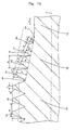
- FIG. 13 is a partially enlarged view illustrating the shank part of the bolt shown in FIG. 12;
- FIG. 14 is an enlarged sectional view illustrating the shank part when the transition part of the bolt shown in FIG. 12 is formed in an arc shape;
- FIG. 15 is an enlarged sectional view illustrating the shank part when the transition part of the bolt shown in FIG. 12 is formed in a linear shape
- FIG. 16 is an enlarged sectional view of the other embodiment of the bolt shown in FIG. 12;
- FIG. 17 a front view showing the first helix of the bolt shown in FIG. 12;
- FIG. 18 is a front view showing the first and second helixes of the bolt shown in FIG. 12;
- FIG. 19 is a sectional view of a nut according to the first embodiment of the present invention.
- FIG. 20 is a sectional view of a nut according to the second embodiment of the present invention.
- FIG. 21 is a partially sectional view showing the state in which the bolt is obliquely inserted into the nut according to the present invention.
- FIGS. 1 and 2 show the bolt according to the first embodiment of the present invention.
- the bolt has a bolt shank 2 , an inclined part 11 , and a constant diameter cylindrical part 12 .
- a normal screw thread 1 with a predetermined pitch is formed on the bolt shank 2 .
- the constant diameter cylindrical part 12 with a diameter smaller than that of the bolt shank 2 is provided at a tip portion of the bolt shank 2 via the tapered inclined part 11 .
- the inclined part 11 has a predetermined length in the axial direction, for example, a length 1 to 1.5 times as long as that of the one pitch of the normal screw thread 1 .
- a deformed screw thread 13 is formed on the tapered inclined part 11 with the same pitch as that of the normal screw thread 1 and in such a shape that the crest thereof is truncated.
- the cross sectional shape of the deformed screw thread 13 in the plane including the axis is approximately trapezoid.
- the deformed screw thread 13 is formed so as to be continuously connected to the screw thread formed on the constant diameter cylindrical part 12 at the tip portion of the bolt.
- the deformed screw thread 13 formed on the constant diameter cylindrical portion 12 is formed so as to have a major diameter a little smaller than the minor diameter of the female screw 7 formed on the nut (refer to FIG. 6) and to have a minor diameter almost equal to that of the screw thread 1 , a shallow screw groove 15 is formed on the constant diameter cylindrical part 12 .
- FIGS. 3 and 4 show the bolt according to the second embodiment of the present invention.
- an arc-shaped inclined part 14 which is slightly convex outwardly is formed instead of the tapered inclined part 11 .
- a deformed screw thread 18 is formed on the arc-shaped inclined part 14 and the constant diameter cylindrical part 12 . It is also possible to use an arc-shaped inclined part which slightly concave inwardly as the arc-shaped inclined part 14 .
- the bolt By forming the bolt having the shape as described above, an almost flat part is more widely formed on the crest of the screw thread formed on the tapered inclined part 11 or the arc-shaped inclined part 14 than on the normal screw thread 1 . Therefore, even when the bolt is obliquely screwed in the nut, the biting of the deformed screw thread 13 or 18 to the screw thread 10 of the nut can be prevented as shown in FIG. 5 . Furthermore, the major diameter of the deformed screw thread 13 or 18 formed on the constant diameter cylindrical part 12 is slightly smaller than the minor diameter of the female screw 7 of the nut. Therefore, it is possible to prevent the large inclination of the bolt with respect to the nut when the bolt is inserted into the nut as shown in FIG. 6 . In addition, since the depth of the screw groove 15 provided on the constant diameter cylindrical part 12 is small, even when the screw thread 8 of the female screw 7 screws into the screw groove 15 , the bolt is not largely inclined.
- the bolt according to the third embodiment of the present invention is shown in FIG. 7 .
- no screw thread is formed on the constant diameter cylindrical part 12 formed at the tip portion of the arc-shaped inclined part 14 .
- This constant diameter cylindrical part 12 is formed so as to have the major diameter a little smaller than the minor diameter of the female screw 7 . Therefore, the bolt is little inclined when the tip portion thereof is inserted into the nut.
- the bolt according to the fourth embodiment of the present invention is shown in FIG. 8 .
- the constant diameter cylindrical part 19 is provided at the tip portion of the arc-shaped inclined part 14 .
- a complete screw thread 16 has a major diameter a little smaller than the minor diameter of the female screw 7 and is formed at the same pitch as that of the normal screw thread 1 on this constant diameter cylindrical part 19 .
- the deformed screw thread 30 is formed on the arc-shaped inclined part 14 . Therefore, when the bolt is obliquely inserted into the nut, the biting between deformed screw thread 30 and the incomplete screw thread 10 of the female screw 7 is prevented. Furthermore, even when the bolt is obliquely inserted into the nut and then is tightened, a screw groove 27 between the incomplete screw thread 16 guides the female screw 7 to the normal screw thread 1 of the bolt shank 2 . Accordingly, the orientation of the bolt is appropriately adjusted, and the bolt can be precisely screwed in the nut.
- the above-mentioned arc-shaped inclined part 14 can be changed to the same shape as the tapered-shaped inclined part 14 .
- FIG. 11 the bolt according to the fifth embodiment of the present invention is shown in FIG. 11 .
- a spiral-shaped convex portion 17 is formed on a constant diameter cylindrical part 28 at the tip portion of the tapered inclined part 11 . It is possible to appropriately adjust the orientation of the bolt with respect to the nut as in the case of FIG. 6 .
- the cross sectional shape of the spiral-shaped convex portion 17 can be optionally selected from the square shape, the semicircular shape, and the like in addition to the triangle shape.
- the tapered shape means straight line shape.
- FIG. 12 is a front view showing the entire outline of a bolt 100
- FIG. 13 is a partially enlarged view illustrating the screw thread formed on the shank part.
- the bolt 100 shown in FIG. 12 is composed of the head part 102 and the shank part 104 .
- the shank part 104 includes a first constant diameter cylindrical part 120 , a transition part 140 , a cylindrical connection part 160 , and a second constant diameter cylindrical part 180 .
- the first constant diameter cylindrical part 120 extends from the head part 102 .
- the first constant diameter cylindrical part 120 is formed in an approximately cylindrical shape with a predetermined first diameter along the axis direction A shown by the arrow in FIGS. 12 and 13.
- a screw thread 122 with a predetermined pitch as shown in FIG. 13 is formed on the side surface of the first constant diameter cylindrical part 120 .
- the transition part 140 extends from a tip portion 124 of the first constant diameter cylindrical part 120 concentrically with the first constant diameter cylindrical part 120 .
- the transition part 140 has a tapered shape with a diameter gradually decreasing with distance from the head part 102 in the axial direction A.
- a screw thread 142 with a predetermined pitch is formed on the side surface of the transition part 140 .
- the screw thread 142 is formed on the entire side surface of the transition part 140 in this sixth embodiment as shown in FIG. 13 .
- it is also possible to form the screw thread 142 on a part of the side surface of the transition part 140 for example, only the adjacent region to the first constant diameter cylindrical part 120 .
- the cylindrical connection part 160 extends from a tip portion 144 of the transition part 140 concentrically with the transition part 140 .
- the cylindrical connection part 160 is formed in an approximately cylindrical shape, with a predetermined constant first diameter along the axial direction. As shown in FIG. 13 no screw thread is formed on the side surface of the cylindrical connection part 160 . However, it is also possible to form a screw thread with a predetermined pitch on the side surface of the cylindrical connection part 160 .
- the second constant diameter cylindrical part 180 extends from a tip portion 162 of the cylindrical connection part 160 concentrically with the cylindrical connection part 160 .
- a screw thread 182 with a predetermined pitch is formed on the side surface of the second constant diameter cylindrical part 180 as shown in FIG. 13 .
- the pitch of the screw thread 122 of the first constant diameter cylindrical part 120 is the same as that of the screw thread 182 of the second constant cylindrical part 180 in the sixth embodiment. However, these pitches may also be different from each other.
- FIGS. 14 and 15 are partially enlarged sectional views showing the above-described first constant diameter cylindrical part 120 , the transition part 140 , and the cylindrical connection part 160 . These figures are sectional views taken along the plane in the axial direction A and including the axial line Z.
- the screw thread 122 with a pitch P 1 and a height a is formed on the first constant diameter cylindrical part 120 .
- the screw thread 142 with a pitch P 2 and heights b 1 , b 2 , b 3 , b 4 , or b 1 ′, b 2 ′, b 3 ′, b 4 ′ is formed on the transition part 140 extending from the tip portion 124 of the first constant diameter cylindrical part 120 .
- the pitch is the distance between the corresponding two points of adjacent ridges each other measured in parallel to the axial line Z in the section including the axial line.
- the pitch of the transition part 140 is P 2 as shown in FIGS. 14 and 15.
- the height of the screw thread is the distance between the straight line connecting the crests of the ridge and the straight line connecting the roots measured perpendicularly to the straight line connecting the roots in a sectional shape including the axial line of the screw thread.
- the heights of the screw thread 142 formed on the side surface of the transition part 140 are b 1 , b 2 , b 3 and b 4 , and in FIG. 15, the heights of that are b 1 ′, b 2 ′, b 3 ′ and b 4 ′.
- the lengths of crest of the screw thread 142 on the transition part 140 in the cross section including the axial line Z are n 1 , n 2 , n 3 and n 4 in FIG. 14, or n 1 ′, n 2 ′, n 3 ′ and n 4 ′ in FIG. 15 .
- the screw thread 142 is formed on the transition part 140 so that these lengths are longer than the length m of the crest in the cross section including axial line Z of the screw thread 122 of the first constant diameter cylindrical part 120 .
- the crest means the surface at the top of the ridge connecting its both side flanks, and the flank means the surface connecting crest and the root.
- the screw thread 142 is formed on the transition part 140 so that the heights of the screw thread b 1 , b 2 , b 3 and b 4 , or b 1 ′, b 2 ′, b 3 ′ and b 4 ′ are gradually decreased with distance from the head part 102 (refer to FIG. 12 ), more specifically, in the lateral direction of FIGS. 14 and 15.
- the line L 1 obtained by connecting the crests of the screw thread 142 formed on the side surface of the transition part 140 is a curved line.
- line L 2 may also be a straight line.
- the heights of the screw thread 142 formed on the transition part 140 b 1 , b 2 , b 3 and b 4 , or b 1 ′, b 2 ′, b 3 ′ and b 4 ′ are simply decreased with distance from the head part 102 (refer to FIG. 12 ).
- FIG. 16 is a partially enlarged sectional view according to other embodiment of the first constant diameter cylindrical part 120 , the transition part 140 and the cylindrical connection part 160 .
- FIG. 16 is a sectional view in cross section including the axial line Z as in the case of FIG. 14 or 15 .
- the minor diameter R 2 of the screw thread 142 on the transition part 140 is the same as the minor diameter R 1 of the screw thread 122 on the first constant diameter cylindrical part 120 .
- the minor diameter is the diameter of imaginary cylinder tangential to the root of mail thread.
- the radius of the root of the screw thread 122 is represented by R 1 / 2 and that of the screw thread 142 is represented by R 2 / 2 in FIG. 16 .
- the screw thread 122 with a pitch P 1 and a height a is formed on the first constant diameter cylindrical part 120 .
- the screw thread 142 with a pitch P 3 and heights b 1 ′′, b 2 ′′ and b 3 ′′ is formed on the transition part 140 extending from tip portion 124 of the first constant diameter cylindrical part 120 .
- the pitch is the distance between the corresponding two points of adjacent ridges each other measured in parallel to the axial line Z in the section including the axial line Z.
- the height is the distance between the straight line connecting the crests ridges and the straight line connecting the roots measured perpendicularly to the axial line Z in the section including the axial line Z.
- Lengths of crest of the screw thread 142 on the transition part 140 in the cross section including the axial line Z are n 1 ′′, n 2 ′′ and n 3 ′′ in FIG. 16 .
- the screw thread 142 is formed on the transition part 140 so that these lengths are longer than the length m of the crest of the screw thread 122 of the first constant diameter cylindrical part 120 in the section including axial line Z as in the case of FIG. 14 or 15 .
- the crest is the surface at the top of the ridge connecting its both flanks, and the flank is the surface connecting the crest and the root.
- the screw thread 142 is formed on the transition part 140 so that the heights of the screw thread b 1 ′′, b 2 ′′ and b 3 ′′ are gradually decreased with distance from the head part 102 (refer to FIG. 12 ), more specifically, in the lateral direction of FIG. 16 .
- the line L 3 obtained by connecting the crests of the screw thread 142 formed on the side surface of the transition part 140 is a curved line.
- the line L 3 may also be a straight line.
- the screw thread 142 of the transition part 140 is formed in the shape like that obtained by truncating the crest of a complete screw thread such as the screw thread 122 of the first constant diameter cylindrical part 120 by a predetermined height. Since the crest of the screw thread is truncated as described above, the length of the crest in the cross section of the screw thread 142 of the transition part 140 is larger than that of the complete screw thread.
- the bolt according to the present invention can be manufactured by the form rolling process by preparing a blank on which no screw thread is formed.
- the bolt shown in FIG. 14, 15 or 16 can be manufactured by the manner in which the shape of blank corresponding with the transition part 140 and/or the shape of rolling die make a change as appropriate.
- FIG. 17 A helix H 1 of the screw thread 122 formed on the side surface of the first constant diameter cylindrical part 120 , and a helix H 2 of the screw thread 142 formed on the transition part 140 are shown in FIG. 17 .
- the helix mentioned above means the locus of a point of which ratio of the travel in axial direction to the rotary angle around the axial line is constant.
- the helix H 1 is represented by a dashed line
- the helix H 2 is represented by a chain line.
- FIG. 17 shows only the helixes H 1 and H 2 in the vicinity of the tip portion 124 of the first constant diameter cylindrical part 120 , and the helixes in the other region is omitted.
- the line along the root of the screw thread 122 formed on the side surface of the first constant diameter cylindrical part 120 and the line along the root of the screw thread 142 formed on the side surface of the transition part 140 are shown as an example of the helix.
- the screw threads 122 and 142 are formed so that the helix H 1 and H 2 are connected to each other at a point 126 in FIG. 17 .
- FIG. 18 shows an imaginary helix H 3 obtained on assumption that the helix of the screw thread 122 formed on the side surface of the first constant diameter cylindrical part 120 is extended and the screw thread is formed on the side surfaces of the transition part 140 and the cylindrical connection part 160 and a helix H 4 of the screw thread 182 formed on the second constant diameter cylindrical part 180 .
- the imaginary helix H 3 along the root of the screw thread 122 formed on the side surface of the first constant diameter cylindrical part 120 is represented by a dashed line
- the helix H 4 along the root of the screw thread 182 formed on the second constant diameter cylindrical part 180 is represented by a chain double-dashed line.
- the screw threads 142 and 182 are formed so as not to continuously connect the imaginary helix H 3 and helix H 4 as shown in a region 166 enclosed by the heavy line in FIG. 18 .
- the screw threads 142 and 182 may also be formed so as to continuously connect the imaginary helix H 3 and helix H 4 .
- the biting of the screw thread can be prevented similarly to the case shown in FIG. 5 . Furthermore, since the biting of the screw thread can be prevented, the orientation of the bolt 100 can be appropriately adjusted, and thus, it becomes possible to easily screw the bolt 100 into the nut 260 as the case of the FIG. 6 .
- transition part and the second constant diameter cylindrical part in the sixth embodiment correspond to the inclined part and the constant diameter cylindrical part in the first to fifth embodiments respectively.
- FIG. 19 shows the nut according to the first embodiment of the present invention.
- a screw hole 20 is formed in this nut.
- a tapered varying diameter part 22 that is linearly chamfered is formed in the vicinity of an opening 21 of the screw hole 20 .
- This varying diameter part 22 has a minor diameter gradually decreasing with distance from the opening 21 of the screw hole, and a screw thread 23 with a predetermined pitch is formed on the varying diameter part 22 .
- the screw hole 20 includes a constant diameter screw thread part 25 adjacent to the varying diameter part 22 , on which a screw thread 8 with a predetermined pitch is formed, and having an approximately constant minor diameter.
- the screw thread 23 formed on the above-described varying diameter part 22 is designed so that a length in the axial direction on the crest of the screw thread 23 is larger than that on the top of the screw thread 8 in the axial direction formed on the constant diameter screw thread part 25 .
- FIG. 20 shows the nut according to the second embodiment of the present invention.
- a varying diameter part 24 in an arc shape which is slightly convex inwardly is formed in the vicinity of an opening 21 of the screw hole 20 .
- the varying diameter part 24 has an minor diameter gradually decreasing with distance from the opening 21 of the screw hole, and a screw thread 26 with a predetermined pitch is formed on the varying diameter part 24 .
- the screw hole 20 includes a constant diameter screw thread part 25 adjacent to the varying diameter part 24 , on which the screw thread 8 with a predetermined pitch is formed, and having an approximately constant minor diameter.
- the screw thread 26 formed on the above-described varying diameter part 24 is designed so that a length in the axial direction on the top of the screw thread 26 is larger than that on the top of the screw thread 8 in the axial direction formed on the constant diameter screw thread part 25 .
- the varing diameter part is formed in the vicinity of the both opening 21 (upper side and lower side) of the screw hole 20 .
- the varing diameter part may also be formed in the vicinity of only one opening 21 to which the bolt is inserted.
Landscapes
- Engineering & Computer Science (AREA)
- General Engineering & Computer Science (AREA)
- Mechanical Engineering (AREA)
- Transmission Devices (AREA)
- Surgical Instruments (AREA)
- Forging (AREA)
- Mutual Connection Of Rods And Tubes (AREA)
Applications Claiming Priority (6)
| Application Number | Priority Date | Filing Date | Title |
|---|---|---|---|
| JP2001-291045 | 2001-09-25 | ||
| JP291045/2001 | 2001-09-25 | ||
| JP2001291045 | 2001-09-25 | ||
| JP2002274363A JP4171631B2 (ja) | 2001-09-25 | 2002-09-20 | ボルト |
| JP2002-274363 | 2002-09-20 | ||
| JP274363/2002 | 2002-09-20 |
Publications (2)
| Publication Number | Publication Date |
|---|---|
| US20030059275A1 US20030059275A1 (en) | 2003-03-27 |
| US6796761B2 true US6796761B2 (en) | 2004-09-28 |
Family
ID=26622793
Family Applications (1)
| Application Number | Title | Priority Date | Filing Date |
|---|---|---|---|
| US10/253,040 Expired - Lifetime US6796761B2 (en) | 2001-09-25 | 2002-09-24 | Bolt and nut |
Country Status (4)
| Country | Link |
|---|---|
| US (1) | US6796761B2 (fr) |
| EP (1) | EP1296070B1 (fr) |
| JP (1) | JP4171631B2 (fr) |
| DE (1) | DE60217782T2 (fr) |
Cited By (16)
| Publication number | Priority date | Publication date | Assignee | Title |
|---|---|---|---|---|
| WO2004113736A2 (fr) * | 2003-06-17 | 2004-12-29 | Newfrey Llc | Attache filetee inviolable |
| US20060222472A1 (en) * | 2001-08-20 | 2006-10-05 | Maclean-Fogg Company | Fastener assembly |
| US20070028741A1 (en) * | 2004-05-26 | 2007-02-08 | Bhs Corrugated Maschinen-Und Anlagenbau Gmbh | Brush cylinder |
| US20090060676A1 (en) * | 2005-06-13 | 2009-03-05 | Aoyama Seisakusho Co., Ltd. | Bolt |
| US20100068003A1 (en) * | 2008-09-16 | 2010-03-18 | Frank Wagner | Anti-Cross Threading Screw |
| US20110072927A1 (en) * | 2009-09-30 | 2011-03-31 | Gilbas Russel A | Method and apparatus for attachment of a lead screw to a motor shaft |
| US20110200410A1 (en) * | 2008-10-02 | 2011-08-18 | Aoyama Seisakusho Co., Ltd. | Anti cross-thread bolt |
| US20130006306A1 (en) * | 2006-09-26 | 2013-01-03 | Synthes Gmbh | Transconnector |
| US8419332B2 (en) | 2007-10-19 | 2013-04-16 | Atlas Bolt & Screw Company Llc | Non-dimpling fastener |
| US20150105829A1 (en) * | 2012-05-22 | 2015-04-16 | Austofix Group Limited | Bone fixation device |
| US20150316089A1 (en) * | 2014-05-01 | 2015-11-05 | Research Engineering & Manufacturing Inc. | Fastener system comprising an externally threaded bolt and an internally threaded nut for the avoidance of cross-threading of the mating threads during assembly |
| US20160177992A1 (en) * | 2014-12-19 | 2016-06-23 | Lung-Chang Lin | Connector for Steel Reinforcing Bars |
| US20180355904A1 (en) * | 2017-06-13 | 2018-12-13 | Iwata Bolt Co., Ltd. | Bolt |
| US10895227B2 (en) * | 2018-07-11 | 2021-01-19 | Mann+Hummel Gmbh | Assembly for receiving a fluid subjected to fluctuating pressure, in particular in the intake manifold of an internal combustion engine |
| US11174888B2 (en) * | 2017-07-10 | 2021-11-16 | Mr Industrial Fasteners S.R.L. | Threaded pin |
| US11209038B2 (en) * | 2016-11-11 | 2021-12-28 | Meidoh Co., Ltd. | Bolt |
Families Citing this family (14)
| Publication number | Priority date | Publication date | Assignee | Title |
|---|---|---|---|---|
| JP2005034939A (ja) * | 2003-07-14 | 2005-02-10 | Hitachi Tool Engineering Ltd | 切刃部材、工具保持具及び切削工具 |
| FR2916624B1 (fr) * | 2007-05-29 | 2009-08-21 | Small Bone Innovations Interna | Vis a os, notamment d'osteosynthese |
| JP2009257477A (ja) * | 2008-04-17 | 2009-11-05 | Nsk Ltd | 自在継手 |
| JP2010111435A (ja) * | 2008-10-09 | 2010-05-20 | Toho Kohan Kk | 容器の締付バンド及びその締結具の製造方法 |
| EP2550933A1 (fr) * | 2011-07-28 | 2013-01-30 | The Procter & Gamble Company | Aide pour la manipulation de fil dentaire |
| EP2752589A4 (fr) * | 2011-08-31 | 2015-04-22 | Aoyama Seisakusho | Écrou anti-grippage |
| JPWO2013030970A1 (ja) * | 2011-08-31 | 2015-03-23 | 株式会社青山製作所 | 焼付き防止ナット |
| WO2015072490A1 (fr) * | 2013-11-15 | 2015-05-21 | 株式会社小糸製作所 | Vis de visée |
| US9644665B2 (en) | 2015-03-27 | 2017-05-09 | Mathread Inc. | Method for correcting translational misalignment between male and female fastener members |
| US9644663B2 (en) | 2015-03-27 | 2017-05-09 | Mathread Inc. | Anti-false threading fastener system |
| US9644664B2 (en) | 2015-03-27 | 2017-05-09 | Mathread Inc. | Male anti-false thread fastener member |
| FR3039231B1 (fr) * | 2015-07-22 | 2018-03-16 | Rdo Alpha | Boulon a devissage freine |
| JP2020020457A (ja) * | 2018-08-03 | 2020-02-06 | 株式会社ブリヂストン | おねじ部材、めねじ部材、及び、ねじ締結構造 |
| US10927877B2 (en) * | 2019-01-11 | 2021-02-23 | Mathread, Inc. | Shortened fastener with locally controlled thread height |
Citations (8)
| Publication number | Priority date | Publication date | Assignee | Title |
|---|---|---|---|---|
| US1939737A (en) * | 1931-06-24 | 1933-12-19 | Dardelet Threadlock Corp | Latch pivot for pneumatic hammer devices |
| US2021704A (en) | 1932-01-25 | 1935-11-19 | United Screw And Bolt Corp | Screw |
| US3266363A (en) | 1964-04-21 | 1966-08-16 | Elastic Stop Nut Corp | Nuts with load distributing threads |
| US3878759A (en) | 1972-12-29 | 1975-04-22 | Textron Inc | Bi-lobular self-thread forming fastener |
| US4179976A (en) * | 1978-03-03 | 1979-12-25 | Illinois Tool Works Inc. | Extruding and tapping screw and blank for manufacture of such screw |
| US4621963A (en) * | 1984-03-26 | 1986-11-11 | Elco Industries, Inc. | Fastener for roof assemblies and the like |
| US6120227A (en) | 1998-07-07 | 2000-09-19 | Aoyama Seisakusho Co., Ltd | Self-aligning bolt |
| US6142186A (en) | 1997-01-17 | 2000-11-07 | Textron Inc. | Thread-forming pipe plug |
Family Cites Families (5)
| Publication number | Priority date | Publication date | Assignee | Title |
|---|---|---|---|---|
| EP0109528B1 (fr) * | 1982-11-23 | 1986-07-30 | Kerb-Konus-Vertriebs-GmbH | Insert taraudé autotaraudeur |
| JP2542275Y2 (ja) * | 1992-01-08 | 1997-07-23 | 株式会社トープラ | パイロット付きボルト |
| JP2001082430A (ja) * | 1999-09-14 | 2001-03-27 | Iwata Bolt Kk | ボルト |
| JP3469846B2 (ja) * | 1999-07-13 | 2003-11-25 | 株式会社メイドー | 案内ボス部溝付ボルト |
| JP2001124103A (ja) * | 1999-10-29 | 2001-05-08 | Nsk Ltd | 自在継手 |
-
2002
- 2002-09-20 JP JP2002274363A patent/JP4171631B2/ja not_active Expired - Fee Related
- 2002-09-24 US US10/253,040 patent/US6796761B2/en not_active Expired - Lifetime
- 2002-09-25 DE DE60217782T patent/DE60217782T2/de not_active Expired - Lifetime
- 2002-09-25 EP EP02021458A patent/EP1296070B1/fr not_active Expired - Lifetime
Patent Citations (8)
| Publication number | Priority date | Publication date | Assignee | Title |
|---|---|---|---|---|
| US1939737A (en) * | 1931-06-24 | 1933-12-19 | Dardelet Threadlock Corp | Latch pivot for pneumatic hammer devices |
| US2021704A (en) | 1932-01-25 | 1935-11-19 | United Screw And Bolt Corp | Screw |
| US3266363A (en) | 1964-04-21 | 1966-08-16 | Elastic Stop Nut Corp | Nuts with load distributing threads |
| US3878759A (en) | 1972-12-29 | 1975-04-22 | Textron Inc | Bi-lobular self-thread forming fastener |
| US4179976A (en) * | 1978-03-03 | 1979-12-25 | Illinois Tool Works Inc. | Extruding and tapping screw and blank for manufacture of such screw |
| US4621963A (en) * | 1984-03-26 | 1986-11-11 | Elco Industries, Inc. | Fastener for roof assemblies and the like |
| US6142186A (en) | 1997-01-17 | 2000-11-07 | Textron Inc. | Thread-forming pipe plug |
| US6120227A (en) | 1998-07-07 | 2000-09-19 | Aoyama Seisakusho Co., Ltd | Self-aligning bolt |
Cited By (27)
| Publication number | Priority date | Publication date | Assignee | Title |
|---|---|---|---|---|
| US20060222472A1 (en) * | 2001-08-20 | 2006-10-05 | Maclean-Fogg Company | Fastener assembly |
| US7410337B2 (en) | 2001-08-20 | 2008-08-12 | The Maclean-Fogg Company | Fastener assembly |
| WO2004113736A3 (fr) * | 2003-06-17 | 2007-01-18 | Newfrey Llc | Attache filetee inviolable |
| WO2004113736A2 (fr) * | 2003-06-17 | 2004-12-29 | Newfrey Llc | Attache filetee inviolable |
| US20070028741A1 (en) * | 2004-05-26 | 2007-02-08 | Bhs Corrugated Maschinen-Und Anlagenbau Gmbh | Brush cylinder |
| US8468921B2 (en) * | 2004-05-26 | 2013-06-25 | Bhs Corrugated Maschinen-Und Anlagenbau Gmbh | Brush cylinder |
| US20090060676A1 (en) * | 2005-06-13 | 2009-03-05 | Aoyama Seisakusho Co., Ltd. | Bolt |
| US7866930B2 (en) * | 2005-06-13 | 2011-01-11 | Aoyama Seisakusho Co., Ltd. | Bolt |
| US20130006306A1 (en) * | 2006-09-26 | 2013-01-03 | Synthes Gmbh | Transconnector |
| US8784452B2 (en) * | 2006-09-26 | 2014-07-22 | DePuy Synthes Products, LLC | Transconnector |
| US8419332B2 (en) | 2007-10-19 | 2013-04-16 | Atlas Bolt & Screw Company Llc | Non-dimpling fastener |
| US20100068003A1 (en) * | 2008-09-16 | 2010-03-18 | Frank Wagner | Anti-Cross Threading Screw |
| US8197170B2 (en) | 2008-09-16 | 2012-06-12 | Kamax-Werke Rudolf Kellermann Gmbh & Co. Kg | Anti-cross threading screw |
| DE102008042141A1 (de) * | 2008-09-16 | 2010-03-25 | Kamax-Werke Rudolf Kellermann Gmbh & Co. Kg | Selbstzentrierende Schraube |
| US20110200410A1 (en) * | 2008-10-02 | 2011-08-18 | Aoyama Seisakusho Co., Ltd. | Anti cross-thread bolt |
| US8632288B2 (en) * | 2008-10-02 | 2014-01-21 | Aoyama Seisakusho Co., Ltd. | Anti cross-thread bolt |
| US20110072927A1 (en) * | 2009-09-30 | 2011-03-31 | Gilbas Russel A | Method and apparatus for attachment of a lead screw to a motor shaft |
| US20150105829A1 (en) * | 2012-05-22 | 2015-04-16 | Austofix Group Limited | Bone fixation device |
| US20150316089A1 (en) * | 2014-05-01 | 2015-11-05 | Research Engineering & Manufacturing Inc. | Fastener system comprising an externally threaded bolt and an internally threaded nut for the avoidance of cross-threading of the mating threads during assembly |
| US9835193B2 (en) * | 2014-05-01 | 2017-12-05 | Research Engineering & Manufacturing Inc. | Fastener system comprising an externally threaded bolt and an internally threaded nut for the avoidance of cross-threading of the mating threads during assembly |
| US10690170B2 (en) | 2014-05-01 | 2020-06-23 | Research Engineering & Manufacturing, Inc. | Fastener system comprising an externally threaded bolt and an internally threaded nut for the avoidance of cross-threading of the mating threads during assembly |
| US20160177992A1 (en) * | 2014-12-19 | 2016-06-23 | Lung-Chang Lin | Connector for Steel Reinforcing Bars |
| US11209038B2 (en) * | 2016-11-11 | 2021-12-28 | Meidoh Co., Ltd. | Bolt |
| US20180355904A1 (en) * | 2017-06-13 | 2018-12-13 | Iwata Bolt Co., Ltd. | Bolt |
| US10837484B2 (en) * | 2017-06-13 | 2020-11-17 | Iwata Bolt Co., Ltd. | Bolt |
| US11174888B2 (en) * | 2017-07-10 | 2021-11-16 | Mr Industrial Fasteners S.R.L. | Threaded pin |
| US10895227B2 (en) * | 2018-07-11 | 2021-01-19 | Mann+Hummel Gmbh | Assembly for receiving a fluid subjected to fluctuating pressure, in particular in the intake manifold of an internal combustion engine |
Also Published As
| Publication number | Publication date |
|---|---|
| EP1296070B1 (fr) | 2007-01-24 |
| US20030059275A1 (en) | 2003-03-27 |
| JP4171631B2 (ja) | 2008-10-22 |
| DE60217782D1 (de) | 2007-03-15 |
| JP2003172330A (ja) | 2003-06-20 |
| DE60217782T2 (de) | 2007-11-15 |
| EP1296070A2 (fr) | 2003-03-26 |
| EP1296070A3 (fr) | 2003-08-13 |
Similar Documents
| Publication | Publication Date | Title |
|---|---|---|
| US6796761B2 (en) | Bolt and nut | |
| US5088869A (en) | Thread rolling screw | |
| US7101133B2 (en) | Thread-forming screw fastener | |
| US6062786A (en) | Anti-cross treading fastener lead-in point | |
| US10274002B2 (en) | Self-tapping screw and screwed fastening as well as blank for manufacturing the screw | |
| US8360701B2 (en) | Threaded fastener | |
| US20080080953A1 (en) | Screw for plastic articles | |
| EP2396561B1 (fr) | Vis formant des filets à auto-filetage autonome et matrice à rouleaux correspondante | |
| JP4225546B2 (ja) | タッピンねじ | |
| JP2010249321A (ja) | ネジ山付留め具のための渦巻型駆動システム | |
| US4981406A (en) | Fastener screw thread and pilot to avoid cross threading | |
| JPS584207B2 (ja) | ネジヤマスエコミネジ | |
| EP1775483A1 (fr) | Vis anti-desserrage | |
| US6561741B2 (en) | Fastener with aligning lead thread | |
| JP2001082430A (ja) | ボルト | |
| JPH09184506A (ja) | タッピンねじ | |
| US6516650B1 (en) | Rolling dies for producing dog point threads | |
| CN113251054B (zh) | 外螺纹部件 | |
| US5842923A (en) | Screw and method for its production | |
| JP2002349536A (ja) | 緩み止めねじ | |
| JP3048317B2 (ja) | ボルト及びこのボルトとナットを用いた締結装置 | |
| US5868536A (en) | Male screw and method for manufacturing same | |
| JPH07269542A (ja) | タッピンねじ | |
| EP0942181A3 (fr) | Elément de fixation fileté empêchant l'engagement de travers | |
| AU2003204363B2 (en) | Fastener with aligning lead thread |
Legal Events
| Date | Code | Title | Description |
|---|---|---|---|
| AS | Assignment |
Owner name: AOYAMA SEISAKUSHO CO., LTD., JAPAN Free format text: ASSIGNMENT OF ASSIGNORS INTEREST;ASSIGNORS:MIZUNO, HIROMICHI;HAMADA, MASAHIKO;OSAWA, TETSUYA;AND OTHERS;REEL/FRAME:013508/0727 Effective date: 20021025 |
|
| STCF | Information on status: patent grant |
Free format text: PATENTED CASE |
|
| FPAY | Fee payment |
Year of fee payment: 4 |
|
| FPAY | Fee payment |
Year of fee payment: 8 |
|
| FPAY | Fee payment |
Year of fee payment: 12 |