US6792380B2 - Attitude angle detecting apparatus - Google Patents
Attitude angle detecting apparatus Download PDFInfo
- Publication number
- US6792380B2 US6792380B2 US10/356,614 US35661403A US6792380B2 US 6792380 B2 US6792380 B2 US 6792380B2 US 35661403 A US35661403 A US 35661403A US 6792380 B2 US6792380 B2 US 6792380B2
- Authority
- US
- United States
- Prior art keywords
- attitude
- integer ambiguity
- attitude angles
- detecting apparatus
- angle detecting
- Prior art date
- Legal status (The legal status is an assumption and is not a legal conclusion. Google has not performed a legal analysis and makes no representation as to the accuracy of the status listed.)
- Expired - Lifetime
Links
Images

Classifications
-
- G—PHYSICS
- G01—MEASURING; TESTING
- G01S—RADIO DIRECTION-FINDING; RADIO NAVIGATION; DETERMINING DISTANCE OR VELOCITY BY USE OF RADIO WAVES; LOCATING OR PRESENCE-DETECTING BY USE OF THE REFLECTION OR RERADIATION OF RADIO WAVES; ANALOGOUS ARRANGEMENTS USING OTHER WAVES
- G01S19/00—Satellite radio beacon positioning systems; Determining position, velocity or attitude using signals transmitted by such systems
- G01S19/38—Determining a navigation solution using signals transmitted by a satellite radio beacon positioning system
- G01S19/39—Determining a navigation solution using signals transmitted by a satellite radio beacon positioning system the satellite radio beacon positioning system transmitting time-stamped messages, e.g. GPS [Global Positioning System], GLONASS [Global Orbiting Navigation Satellite System] or GALILEO
- G01S19/53—Determining attitude
- G01S19/54—Determining attitude using carrier phase measurements; using long or short baseline interferometry
- G01S19/55—Carrier phase ambiguity resolution; Floating ambiguity; LAMBDA [Least-squares AMBiguity Decorrelation Adjustment] method
Definitions
- This invention relates to an attitude angle detecting apparatus for detecting the heading and attitude of a mobile unit, such as an aircraft or a ship.
- attitude angle detecting apparatus for detecting the heading and attitude of a mobile unit.
- One type of such apparatus receives radio waves transmitted from a plurality of position-fixing satellites with multiple antennas located at specific positions of a mobile unit, one of the antennas being used as a reference antenna, measures phases of carrier signals of the radio waves, and determines relative positions of the antennas other than the reference antenna with respect to the reference antenna to determine the heading and attitude of a mobile unit.
- Another type of such apparatus determines the attitude of a mobile unit by use of an angular velocity sensor like a rate gyro for measuring the turning rate of a mobile unit.
- the aforementioned apparatus designed to determine the heading and attitude of a mobile unit from the radio waves transmitted from a plurality of position-fixing satellites makes use of important elementary technology for resolving carrier phase ambiguities.
- the apparatus estimates the attitude angles by using an attitude angle detecting device, such as the aforementioned angular velocity sensor.
- attitude angle detecting device such as the aforementioned angular velocity sensor.
- the length of a baseline is 3 m and the radio waves from the position-fixing satellites are interrupted for one minute, for example, it will take one to two minutes on average up to about 15 minutes at maximum to redetermine initial integer ambiguity values after the interruption.
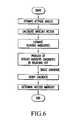
- a conventional attitude angle detecting apparatus employing this previously known approach determines the carrier phase ambiguities upon restoring normal reception of the radio waves according to a procedure shown in a flowchart of FIG. 6 .
- the apparatus calculates a baseline vector based on the attitude angles which have been uninterruptedly estimated by the angular velocity sensor while the radio waves have been interrupted.
- the apparatus calculates floating ambiguities from the baseline vector and rounds off fractional parts of the floating ambiguities to obtain candidates (integer values) of a potentially true integer ambiguity.
- the candidates of the potentially true integer ambiguity so obtained are then examined and one candidate regarded as being correct is taken as the true integer ambiguity.
- the aforementioned time needed for determining the integer ambiguity can be reduced to approximately 8 seconds on average, approximately 30 seconds at maximum.
- the aforementioned conventional attitude angle detecting apparatus has a problem to be solved as described below.
- the accuracy of estimated attitude angles achieved by the aforementioned conventional attitude angle detecting apparatus deteriorates when the radio waves from the position-fixing satellites are interrupted for more than a specific period of time, although this period of time varies from one minute to 5 minutes depending on various conditions.
- the degree of deterioration of the estimated attitude angles is considerably affected by measurement errors of the angular velocity sensor. It is likely that integer ambiguity candidates calculated from estimated values of attitude angles containing such errors do not agree with the true integer ambiguity.
- the integer ambiguity candidates thus calculated are more likely to disagree with the true integer ambiguity as baseline lengths (distances between multiple antennas mounted on a mobile unit) increase and as the period of interruption of the radio waves increases.
- the conventional attitude angle detecting apparatus has a potential to incorrectly determine integer ambiguity candidates and provide wrong attitude angles as mentioned above. If the baseline length is 3 m and the period of interruption of the radio waves from the position-fixing satellites is one minute, for example, the probability of providing incorrect integer ambiguities could be approximately 1%.
- an attitude angle detecting apparatus comprises means for observing a single phase difference or a double phase difference and determining an integer ambiguity from the single or double phase difference, means for calculating the relative position of an antenna other than a reference antenna with respect to the reference antenna from the phase difference of which integer ambiguity has been determined, means for calculating attitude angles of a mobile unit and an error covariance of the attitude angles, and integer ambiguity redetermination means for calculating at least one integer ambiguity candidate from the single or double phase difference based on the attitude angles and the error covariance of the attitude angles and redetermining the integer ambiguity from the integer ambiguity candidate.
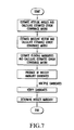
- the attitude angle detecting apparatus thus constructed calculates estimated values of attitude angles, baseline vectors and floating ambiguities as well as covariances of their estimation errors, calculates a plurality of integer ambiguity candidates based on these estimated values and the covariances of their estimation errors and verifies the integer ambiguity candidates so obtained, whereby the apparatus determines a single integer ambiguity and outputs the attitude angles as shown in FIG. 7 .
- attitude angles and the attitude angle error covariance are used in producing the integer ambiguity candidates, it is possible to redetermine the integer ambiguity from the single or double phase difference for measuring the relative positions of the antennas quickly and accurately when it is necessary to redetermine the integer ambiguity after recovery from an interruption of radio waves from position-fixing satellites of the Global Positioning System (GPS).
- GPS Global Positioning System
- an attitude angle detecting apparatus comprises means for observing a single phase difference or a double phase difference and determining an integer ambiguity from the single or double phase difference, means for calculating the relative position of an antenna other than a reference antenna with respect to the reference antenna from the phase difference of which integer ambiguity has been determined, means for calculating attitude angles of a mobile unit and an error covariance of the attitude angles and correcting the error covariance of the attitude angles, and integer ambiguity redetermination means for calculating at least one integer ambiguity candidate from the single or double phase difference based on the attitude angles and the corrected error covariance of the attitude angles and redetermining the integer ambiguity from the integer ambiguity candidate.
- the attitude angle detecting apparatus thus constructed redetermines the integer ambiguity using the attitude angles which have been obtained when it has become impossible to determine the integer ambiguity from the single or double phase difference as well as the error covariance of the attitude angles corrected by a specific correction term.
- the attitude angle detecting apparatus uses both the aforementioned means for determining the integer ambiguity from the attitude angles and the error covariance of the attitude angles and the aforementioned means for determining the integer ambiguity from the single or double phase difference, or selectively uses one of these means, in redetermining the integer ambiguity.
- the apparatus redetermines the integer ambiguity in accordance with situations in which the mobile unit is placed. Specifically, the apparatus redetermines the integer ambiguity quickly and accurately by using or not using the attitude angles and the error covariance of the attitude angles when the radio waves from the position-fixing satellites are not received for a specific period of time or over depending on the duration of interruption of the radio waves, for example.
- the aforementioned means for calculating the attitude angles of the mobile unit and the error covariance of the attitude angles includes an angular velocity sensor and means for calculating the attitude angles from an output of the angular velocity sensor.
- the aforementioned means for calculating the attitude angles of the mobile unit and the error covariance of the attitude angles includes means for predicting the attitude angles and the error covariance of the attitude angles based on an assumed model depending on conditions of the mobile unit.
- the apparatus can determine the integer ambiguity quickly and accurately.
- the integer ambiguity redetermination means includes means for calculating floating ambiguities and an error covariance of the floating ambiguities and/or means for determining the integer ambiguity candidate by the Least-squares AMBiguity Decorrelation Adjustment (LAMBDA) method.
- LAMBDA Least-squares AMBiguity Decorrelation Adjustment
- the apparatus can calculate an estimated value of the integer ambiguity and an estimated error covariance and output a plurality of integer ambiguity candidates.
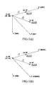
- FIGS. 1A and 1B are diagrams showing an example of an antenna layout depicted in a local coordinate system and an antenna coordinate system, respectively;
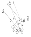
- FIG. 2 is a diagram showing the relationship between a baseline vector and a single phase difference and other parameters
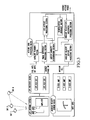
- FIG. 3 is a block diagram showing the construction of an attitude determining system for a mobile unit according to the invention.
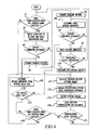
- FIG. 4 is a flowchart showing operations performed by a reinitialization judgment section and an angular velocity/GPS integration processing section of an attitude data processing block shown in FIG. 3;
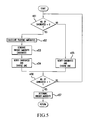
- FIG. 5 is a flowchart showing a procedure of FIG. 4 for determining integer ambiguities from attitude angles and attitude angle error covariance;
- FIG. 6 is a flowchart generally showing a conventional procedure for determining integer ambiguities from attitude angles.
- FIG. 7 is a flowchart generally showing a procedure for determining the integer ambiguities from the attitude angles according to the invention.
- FIGS. 1A and 1B First, an antenna coordinate system, a local coordinate system and coordinate transformation between these two coordinate systems are explained referring to FIGS. 1A and 1B.
- FIG. 1A shows an antenna layout depicted in the local coordinate system, in which the x, y and z axes represent north, east and vertical directions, respectively, with the position of a reference antenna (first antenna) located at an origin, for instance.
- a point shown by coordinates (x 1 n , y 1 n , z 1 n ) is the position of a second antenna
- a point shown by coordinates (x 2 n , y 2 n , z 2 n ) is the position of a third antenna
- L 1 n is a baseline vector taken from the first antenna to the second antenna
- L 2 n is a baseline vector taken from the first antenna to the third antenna.
- FIG. 1B shows an antenna layout depicted in the antenna coordinate system, in which the x axis represents the heading (i.e., the direction in which a ship's bow or the nose of an aircraft is oriented), the y axis corresponds to a direction perpendicular to the x axis, and the z axis indicates a direction perpendicular to both the x and y axes, and the position of the reference antenna (first antenna) is taken as an origin, for instance.
- the x axis represents the heading (i.e., the direction in which a ship's bow or the nose of an aircraft is oriented)
- the y axis corresponds to a direction perpendicular to the x axis
- the z axis indicates a direction perpendicular to both the x and y axes
- the position of the reference antenna (first antenna) is taken as an origin, for instance.
- a point shown by coordinates (x 1 a , y 1 a , z 1 a ) is the position of the second antenna
- a point shown by coordinates (x 2 a , y 2 a , z 2 a ) is the position of the third antenna
- L 1 a is a baseline vector taken from the first antenna to the second antenna
- L 2 a is a baseline vector taken from the first antenna to the third antenna.
- L 3 n is a cross product of L 1 n and L 2 n
- L 3 a is a cross product of L 1 a and L 2 a .
- a coordinate transformation operator C a n of equation (1) is expressed by the following matrix:
- C a n [ cos ⁇ ( ⁇ p ) ⁇ cos ⁇ ( ⁇ y ) sin ⁇ ( ⁇ r ) ⁇ sin ⁇ ( ⁇ p ) ⁇ cos ⁇ ( ⁇ y ) - cos ⁇ ( ⁇ r ) ⁇ sin ⁇ ( ⁇ y ) cos ⁇ ( ⁇ r ) ⁇ sin ⁇ ( ⁇ p ) ⁇ cos ⁇ ( ⁇ y ) + sin ⁇ ( ⁇ r ) ⁇ sin ⁇ ( ⁇ p ) cos ⁇ ( ⁇ y ) sin ⁇ ( ⁇ ⁇ ⁇ ) ⁇ ( ⁇ y ) sin ⁇ ( ⁇ r ) ⁇ ( ⁇ y ) sin ⁇ ( ⁇ r ) ⁇ ( ⁇ y ) sin ⁇ ( ⁇ r ) ⁇ (
- ⁇ r is the angle of roll
- ⁇ p is the angle of pitch
- ⁇ y is the angle of yaw. Since the baseline vector obtained by the GPS is a vector in the local coordinate system, ⁇ y is an attitude angle referenced to true north. Also, ⁇ r and ⁇ p are attitude angles referenced to a horizontal plane. The Euler angles ( ⁇ r, ⁇ p, ⁇ y) are hereinafter referred to as “GPS attitude angles.”
- C a n can be obtained if L 1 n , L 2 n and L 3 n are determined from carrier phase difference observables.
- the attitude angles can be calculated from equations (3) to (5) above.
- an attitude angle determining system usually determines the relative positions of the antennas with high accuracy by observing carrier phase differences rather than by performing position fixing using a pseudorandom noise code. While either a single phase difference method or a double phase difference method may be used for position fixing, the double phase difference method is described in the following discussion:
- ⁇ carrier wavelength of a received signal
- FIG. 2 is a graphical representation of the double phase difference, in which individual symbols have the following meanings:
- ⁇ A is a direction cosine difference matrix taken from double phase differences in the direction of the satellite.
- the error of double phase difference is ⁇ ( ⁇ ) and the error of integer ambiguity is ⁇ ( ⁇ N)
- equation (11) there is a relation expressed by equation (11) below among ⁇ , ⁇ ( ⁇ ) and ⁇ ( ⁇ N):
- equation (14) the relationship between attitude angle errors and the integer ambiguity errors is expressed by equation (14) below:
- equation (16) the relationship between the covariance Qx of baseline vector errors and the covariance Q ⁇ of attitude angle errors is expressed by equation (16) below:
- equation (17) above is identical to equation (18) below:
- the double phase difference error covariance Q ⁇ can be preestimated by a method described below, for example.
- the baseline vector is measured with an apparatus held at a fixed location and observed data (double phase differences and direction cosine difference matrix) are recorded. Then, assuming that a double phase difference from the measured baseline vector and the direction cosine difference matrix is a true value, variances of errors between that value and the observed double phase differences is calculated. A matrix of which diagonal elements are the variances of errors so calculated is used as the aforementioned double phase difference error covariance Q ⁇ .
- the attitude angles and the attitude angle error covariance can be obtained by performing strapdown calculation using angular velocities obtained by the angular velocity sensor.
- the attitude angle error covariance is obtained by adding a correction value, which is obtained by multiplying the duration of interruption of GPS signals by a specific constant ⁇ , to the diagonal elements of the attitude angle error covariance which have been obtained from equation (17) prior to the GPS signal interruption.
- the constant ⁇ is a preset value determined according to such parameters as an angular velocity sensor measurement error, an angular velocity sensor offset bias estimation error and update interval.
- attitude angles which have been obtained from equations (3), (4) and (5) prior to the GPS signal interruption remain unchanged immediately after the GPS signal interruption, those attitude angles are initially used as predicted values of the attitude angles.
- a value obtained by multiplying the duration of the GPS signal interruption by a specific constant ⁇ is added to the diagonal elements of the attitude angle error covariance which have been obtained from equation (17) prior to the GPS signal interruption in order to obtain a predicted value of the attitude angle error covariance.
- the constant ⁇ is a preset value determined according to such parameters as the magnitude of angular velocities and the frequency of the occurrence of the angular velocities. It is also possible to obtain the attitude angle error covariance by making this kind of correction.
- integer ambiguity candidates are produced from the standard deviation of floating ambiguities obtained from the attitude angles and a candidate which is considered most reliable is selected as the potentially true integer ambiguity.
- a candidate which is considered most reliable is selected as the potentially true integer ambiguity.
- d is the length of the baseline vector L 1 a .
- error variance matrices Qx and Q ⁇ and a unit direction cosine difference matrix H are expressed by equations (22) below:
- Qx ⁇ [ ⁇ xx 2 ⁇ xy ⁇ xz ⁇ yx ⁇ yy 2 ⁇ yz ⁇ zx ⁇ zy ⁇ zz 2 ]
- Q ⁇ [ ⁇ p 2 ⁇ py ⁇ yp ⁇ y 2 ]
- Floating ambiguities are calculated as follows from attitude angles.
- a j m is a vector in the direction of viewing field of a satellite m of the baseline vector L j n , it can be determined from the position (x m n , y m n , z m n ) of each satellite and the position (x j n , y j n , z j n ) in the local coordinate system, where m is the number of the satellite used and j is the number of the baseline vector.
- attitude angle error covariance Q ⁇ can be calculated from the earlier-mentioned equation (17), it is possible to calculate the floating ambiguity error covariance Q ⁇ n from equation (25) above.
- the standard deviation ⁇ n of floating ambiguities can be obtained as a root of diagonal elements of the floating ambiguity error covariance Q ⁇ n.
- an integer value existing between a value obtained by adding the aforementioned standard deviation ⁇ n to the floating ambiguity ⁇ n and a value obtained by subtracting the standard deviation ⁇ n from the floating ambiguity ⁇ n can be calculated as an integer ambiguity candidate of the single phase difference.
- ⁇ N is an integer ambiguity candidate
- ⁇ n is a floating ambiguity
- Q ⁇ n is a floating ambiguity error covariance
- ⁇ 2 is the threshold of a norm
- each integer ambiguity candidate is substituted in the inequality (26) which uses the floating ambiguity ⁇ n and the floating ambiguity error covariance Q ⁇ n. If the calculated value of the left side of the inequality (26) is equal to or smaller than the threshold ⁇ 2 of the norm, the integer ambiguity candidate ⁇ N is regarded as true and the result is calculated, in which the threshold ⁇ 2 of the norm is set according to search volume in the actual apparatus.
- the integer ambiguity candidate ⁇ N can be calculated from equation (6) using double phase difference floating ambiguity ⁇ N. Therefore, the invention is applicable to both the single phase difference method and the double phase difference method.
- FIG. 3 is a block diagram of the attitude determining system.
- sat 1 , sat 2 and satN are GPS satellites (position-fixing satellites).
- a GPS antenna system including two antennas ANT 1 , ANT 2 receives radio waves transmitted from the position-fixing satellites sat 1 , sat 2 and satN and downconverts received radio wave signals into intermediate frequency (IF) signals.
- the IF signals are amplified by an amplifier built in the GPS antenna system and delivered to a GPS receiver block.
- the GPS receiver block Based on the signals received by the individual antennas ANT 1 , ANT 2 , the GPS receiver block calculates the positions of the antennas ANT 1 , ANT 2 and carrier phase differences, and outputs these data together with information on the positions of the individual satellites to an attitude data processing block at specific time intervals. Since the antenna positions obtained by position fixing, ephemeris information, etc. comply with the coordinate system of the GPS, these data are converted into the local coordinate system in the GPS receiver block or in the attitude data processing block. In the following discussion, it is assumed that the data are converted in the GPS receiver block.
- a satellite planning section of the attitude data processing block selects satellites to be used based on the satellite ephemeris information and the antenna positions and gives the antenna positions and information on the selected satellites to a phase difference processing section.
- the phase difference processing section calculates observed quantities of single (or double) phase differences from the information received from the satellite planning section and carrier phase difference signals received from the GPS receiver block, and delivers the resultant data to an integer ambiguity determination section.
- the integer ambiguity determination section determines integer ambiguities of the single (or double) phase differences of the relevant satellites, evaluates the goodness of the integer ambiguities, and gives integer ambiguity information to a GPS attitude processing section.
- the GPS attitude processing section calculates baseline vectors in the local coordinate system from the integer ambiguities and carrier phase difference observables output from the phase difference processing section using a known method. Attitude angles are calculated from the baseline vectors for the local coordinate system thus obtained and the known baseline vectors for the antenna coordinate system from equations (1) to (5). The attitude angles obtained by the GPS are hereinafter referred to as “GPS attitude angles.”
- An angular velocity sensor block includes a rate gyro for detecting angular velocities around three perpendicular axes as well as an x-axis amplifier, a y-axis amplifier and a z-axis amplifier for amplifying angular velocity outputs.
- This angular velocity sensor block outputs data on the angular velocities around the individual axes to an angular velocity attitude processing section of the attitude data processing block.
- the angular velocity sensor block outputs angular velocities ⁇ s is about axes of an angular velocity sensor coordinate system referenced to a right-handed inertial coordinate system whose x axis coincides with the line of intersection of the earth's equatorial plane and a meridian plane passing through the vernal equinox and y axis coincides with an eastward-directed line perpendicular to the x axis.
- What are needed here are angular velocities ⁇ s ns about coordinate axes of the angular velocity sensors in the local coordinate system.
- ⁇ s ns ⁇ s is ⁇ s in , where ⁇ s in is an angular velocity obtained when an angular velocity in the local coordinate system referenced to the inertial coordinate system is observed from the angular velocity sensor coordinate system. Since ⁇ s is >> ⁇ s in in the case of a low-speed mobile unit like a ship, ⁇ s is can be disregarded. In the case of a high-speed mobile unit like an aircraft, ⁇ s ns is calculated from the position of the mobile unit using a known method.
- the angular velocity attitude processing section calculates the attitude angles using Euler's equation or Gilmore's algorithm which are known.
- the attitude angles thus obtained are hereinafter referred to as “angular velocity attitude angles.”
- An angular velocity/GPS integration processing section combines the angular velocity attitude angles and the GPS attitude angles and eventually outputs individual attitude angles including the angles of roll, pitch and yaw.
- FIG. 4 is a flowchart showing operations performed by a reinitialization judgment section and the angular velocity/GPS integration processing section of the attitude data processing block shown in FIG. 3 .
- the attitude data processing block Upon receiving radio waves from the position-fixing satellites (step n 1 ), the attitude data processing block selects satellites to be used for position fixing and takes in observation data obtained from the radio waves received from the selected satellites (step n 2 ). If integer ambiguities are not determined yet under initial conditions, baseline vectors are estimated for the individual antennas and floating ambiguities are obtained. A Kalman filter or the least squares method, for instance, is used for this estimation. Subsequently, the integer ambiguities are determined by rounding the floating ambiguities to integer values using a known method (steps n 4 ⁇ n 5 ⁇ n 6 ⁇ n 7 ⁇ n 6 . . . ).
- step n 8 the goodness of the estimated integer ambiguities is verified by conducting a ⁇ 2 -test or and judging whether baseline lengths coincide with actual values. If the result of verification is unsatisfactory, the aforementioned operation for determining the integer ambiguities is reexecuted (steps n 9 ⁇ n 6 . . . ). If the result of verification is satisfactory, baseline vectors are determined using the integer ambiguities so obtained as known quantities, and GPS attitude angles are calculated from relative positions of the individual antennas (step n 10 ). Then, angular velocity attitude angles are calculated from angular velocities around the three axes detected by the angular velocity sensors at the same time that the GPS attitude angles were calculated (step n 11 ).
- the angular velocity/GPS integration processing section performs an angular velocity/GPS attitude angle integration operation to integrate the GPS attitude angles and the angular velocity attitude angles and outputs the attitude angles so integrated (steps n 12 ⁇ n 13 ).
- the angular velocity attitude angles are converted to attitude angles defined in the same local coordinate system as for the GPS attitude angles by using the GPS attitude angles as initial values of strapdown of the angular velocity attitude angles.
- angular velocity sensor errors are estimated from differences between the GPS attitude angles and the angular velocity attitude angles in step n 12 .
- the attitude angle error covariance is calculated by using equations (17) and (25).
- One example of calculation method used in the aforementioned integration operation is to calculate the attitude angles and the attitude angle error covariance using a Kalman filter which outputs attitude angles as a state.
- the aforementioned GPS attitude angles are attitude angles of the axes of the antenna coordinate system referenced to the local coordinate system
- the angular velocity attitude angles are attitude angles of the axes of the angular velocity sensor coordinate system referenced to the local coordinate system.
- the aforementioned estimation of the angular velocity sensor errors is made by estimating biases and drift errors which constitute the angular velocity sensor errors using information on the differences between the GPS attitude angles and the angular velocity attitude angles.
- the angular velocity sensor errors thus estimated are removed from the angular velocity attitude angles.
- the reinitialization judgment section of the attitude data processing block judges whether any cycle slips have occurred (steps n 13 ⁇ n 14 ). If the reinitialization judgment section judges that a cycle slip has occurred, integer ambiguities are determined and baseline vectors are estimated using the attitude angles and the attitude angle error covariance calculated as described above (steps n 15 ⁇ n 16 ⁇ n 17 ⁇ n 18 ⁇ n 4 ).
- FIG. 5 is a flowchart showing how the integer ambiguity determination section determines integer ambiguities from the attitude angles and the attitude angle error covariance upon receipt of a reinitialization signal.
- the integer ambiguity determination section Upon receiving a reinitialization signal, the integer ambiguity determination section begins operation for determining the integer ambiguities from the attitude angles and the attitude angle error covariance. Should there exist integer ambiguity candidates, they are verified to choose one potentially true candidate (steps n 51 ⁇ n 55 ). If there is no integer ambiguity candidate, on the other hand, candidates are generated by a method shown below and one potentially true candidate is selected through verification.
- step n 52 Floating ambiguities are calculated from the baseline vectors so obtained. At least one integer ambiguity candidate is then generated based on the floating ambiguities so obtained, the covariance of errors of the floating ambiguities and the standard deviation of the floating ambiguities, and each integer ambiguity candidate is verified as described above (steps n 53 ⁇ n 54 ). When one potentially true candidate has been chosen through verification, it is determined as the integer ambiguity (steps n 56 ⁇ n 57 ). The aforementioned process of generation and verification of the integer ambiguities is repeatedly executed until one potentially true candidate is selected (steps n 56 ⁇ n 51 . . . ).
- attitude angles are calculated and output by using the GPS attitude angles which have been obtained immediately before the interruption of GPS signals as initial values of strapdown of the angular velocity attitude angles (steps n 16 ⁇ n 11 ⁇ n 12 ⁇ n 13 ).
- the attitude angle error covariance is used after making the aforementioned correction as necessary.
- the attitude angle error covariance increased when the duration of the GPS signal interruption increases (e.g., 15 minutes or over). Therefore, it takes a longer time to determine the integer ambiguities when using the attitude angle error covariance as compared with a case where the attitude angle error covariance is not used. Furthermore, if the integer ambiguities are determined in this way, there arises an increased possibility of incorrectly determining the integer ambiguities. For this reason, a judgment is made to choose whether to use the attitude angles and the attitude angle error covariance for determining the integer ambiguities (steps b 17 ⁇ n 18 ).
- the duration of the GPS signal interruption may be used as a criterion in judging whether to use the attitude angle data in step b 17 .
- the attitude angle data is not used when the radio waves from the GPS position-fixing satellites are not received for a specific period of time or over, whereas the attitude angle data is used when the duration of the GPS signal interruption does not exceed this specific period of time.
- An alternative to this judgment criterion is to use the attitude angle data when the attitude angle error covariance is equal to or smaller than a specific threshold value and not to use the attitude angle data when the attitude angle error covariance exceeds the threshold value.
- Another alternative is to determine the integer ambiguities by a procedure using the attitude angle data and a procedure not using the attitude angle data and employ the integer ambiguities determined by one of these procedures whichever provides the solutions earlier. Still another alternative is to determine the integer ambiguities by alternately using these procedures.
- the invention it is possible to determine the integer ambiguities quickly and accurately by using the attitude angles and the attitude angle error covariance when it is necessary to perform reinitialization after recovery from the GPS signal interruption, for example.
Landscapes
- Engineering & Computer Science (AREA)
- Radar, Positioning & Navigation (AREA)
- Remote Sensing (AREA)
- Computer Networks & Wireless Communication (AREA)
- Physics & Mathematics (AREA)
- General Physics & Mathematics (AREA)
- Position Fixing By Use Of Radio Waves (AREA)
- Gyroscopes (AREA)
Applications Claiming Priority (2)
| Application Number | Priority Date | Filing Date | Title |
|---|---|---|---|
| JP2002-034377 | 2002-02-12 | ||
| JP2002034377A JP2003232845A (ja) | 2002-02-12 | 2002-02-12 | 移動体の方位および姿勢検出装置 |
Publications (2)
| Publication Number | Publication Date |
|---|---|
| US20030154049A1 US20030154049A1 (en) | 2003-08-14 |
| US6792380B2 true US6792380B2 (en) | 2004-09-14 |
Family
ID=19192563
Family Applications (1)
| Application Number | Title | Priority Date | Filing Date |
|---|---|---|---|
| US10/356,614 Expired - Lifetime US6792380B2 (en) | 2002-02-12 | 2003-02-03 | Attitude angle detecting apparatus |
Country Status (3)
| Country | Link |
|---|---|
| US (1) | US6792380B2 (enExample) |
| JP (1) | JP2003232845A (enExample) |
| GB (1) | GB2387727B (enExample) |
Cited By (45)
| Publication number | Priority date | Publication date | Assignee | Title |
|---|---|---|---|---|
| US20050264444A1 (en) * | 2004-01-13 | 2005-12-01 | Sharpe Richard T | Method for combined use of local positioning system and a global positioning system |
| US20060152407A1 (en) * | 2004-01-13 | 2006-07-13 | Hatch Ronald R | Method for combined use of a local positioning system, a local RTK system, and a regional, wide-area, or global carrier-phase positioning system |
| US20070075896A1 (en) * | 2005-10-04 | 2007-04-05 | Csi Wireless, Inc. | Attitude determination exploiting geometry constraints |
| US20070085737A1 (en) * | 2004-01-13 | 2007-04-19 | Eslinger Daniel J | Method for Increasing the Reliability of Position Information When Transitioning from a Regional, Wide-Area, or Global Carrier-Phase Differential Navigation (WADGPS) to a Local Real-Time Kinematic (RTK) Navigation System |
| US20080088504A1 (en) * | 2006-09-29 | 2008-04-17 | Honeywell International Inc. | Carrier phase interger ambiguity resolution with multiple reference receivers |
| US7373231B2 (en) | 2002-12-11 | 2008-05-13 | Hemisphere Gps Llc | Articulated equipment position control system and method |
| US7388539B2 (en) | 2005-10-19 | 2008-06-17 | Hemisphere Gps Inc. | Carrier track loop for GNSS derived attitude |
| US20090091496A1 (en) * | 2007-10-08 | 2009-04-09 | Whitehead Michael L | Gnss receiver and external storage device system and gnss data processing method |
| US20090102708A1 (en) * | 2004-01-13 | 2009-04-23 | Dai Liwen L | Navigation Receiver and Method for Combined Use of a Standard RTK System and a Global Carrier-Phase Differential Positioning System |
| US20100231443A1 (en) * | 2009-03-11 | 2010-09-16 | Whitehead Michael L | Removing biases in dual frequency gnss receivers using sbas |
| US7835832B2 (en) | 2007-01-05 | 2010-11-16 | Hemisphere Gps Llc | Vehicle control system |
| US7885745B2 (en) | 2002-12-11 | 2011-02-08 | Hemisphere Gps Llc | GNSS control system and method |
| US7948769B2 (en) | 2007-09-27 | 2011-05-24 | Hemisphere Gps Llc | Tightly-coupled PCB GNSS circuit and manufacturing method |
| US8000381B2 (en) | 2007-02-27 | 2011-08-16 | Hemisphere Gps Llc | Unbiased code phase discriminator |
| US8018376B2 (en) | 2008-04-08 | 2011-09-13 | Hemisphere Gps Llc | GNSS-based mobile communication system and method |
| US20120029810A1 (en) * | 2010-07-30 | 2012-02-02 | Dai Liwen L | System and Method for Moving-Base RTK Measurements |
| US8138970B2 (en) | 2003-03-20 | 2012-03-20 | Hemisphere Gps Llc | GNSS-based tracking of fixed or slow-moving structures |
| US8140223B2 (en) | 2003-03-20 | 2012-03-20 | Hemisphere Gps Llc | Multiple-antenna GNSS control system and method |
| US8174437B2 (en) | 2009-07-29 | 2012-05-08 | Hemisphere Gps Llc | System and method for augmenting DGNSS with internally-generated differential correction |
| US8190337B2 (en) | 2003-03-20 | 2012-05-29 | Hemisphere GPS, LLC | Satellite based vehicle guidance control in straight and contour modes |
| US8214111B2 (en) | 2005-07-19 | 2012-07-03 | Hemisphere Gps Llc | Adaptive machine control system and method |
| US8217833B2 (en) | 2008-12-11 | 2012-07-10 | Hemisphere Gps Llc | GNSS superband ASIC with simultaneous multi-frequency down conversion |
| US8265826B2 (en) | 2003-03-20 | 2012-09-11 | Hemisphere GPS, LLC | Combined GNSS gyroscope control system and method |
| US8271194B2 (en) | 2004-03-19 | 2012-09-18 | Hemisphere Gps Llc | Method and system using GNSS phase measurements for relative positioning |
| US8311696B2 (en) | 2009-07-17 | 2012-11-13 | Hemisphere Gps Llc | Optical tracking vehicle control system and method |
| US8334804B2 (en) | 2009-09-04 | 2012-12-18 | Hemisphere Gps Llc | Multi-frequency GNSS receiver baseband DSP |
| US8386129B2 (en) | 2009-01-17 | 2013-02-26 | Hemipshere GPS, LLC | Raster-based contour swathing for guidance and variable-rate chemical application |
| US8401704B2 (en) | 2009-07-22 | 2013-03-19 | Hemisphere GPS, LLC | GNSS control system and method for irrigation and related applications |
| US20130069822A1 (en) * | 2011-09-19 | 2013-03-21 | Benjamin Wu | Method and apparatus for differential global positioning system (dgps)-based real time attitude determination (rtad) |
| US8548649B2 (en) | 2009-10-19 | 2013-10-01 | Agjunction Llc | GNSS optimized aircraft control system and method |
| US8583315B2 (en) | 2004-03-19 | 2013-11-12 | Agjunction Llc | Multi-antenna GNSS control system and method |
| US8583326B2 (en) | 2010-02-09 | 2013-11-12 | Agjunction Llc | GNSS contour guidance path selection |
| US8594879B2 (en) | 2003-03-20 | 2013-11-26 | Agjunction Llc | GNSS guidance and machine control |
| US8649930B2 (en) | 2009-09-17 | 2014-02-11 | Agjunction Llc | GNSS integrated multi-sensor control system and method |
| US8686900B2 (en) | 2003-03-20 | 2014-04-01 | Hemisphere GNSS, Inc. | Multi-antenna GNSS positioning method and system |
| US8963764B1 (en) * | 2011-01-14 | 2015-02-24 | Lockheed Martin Corporation | Ship heading and pitch using satellite ephemerides and radar range measurement of satellite |
| US9002566B2 (en) | 2008-02-10 | 2015-04-07 | AgJunction, LLC | Visual, GNSS and gyro autosteering control |
| US9459344B1 (en) | 2011-01-14 | 2016-10-04 | Lockheed Martin Corporation | Ship position and velocity using satellite ephemerides and radar range measurement of satellite |
| US9880562B2 (en) | 2003-03-20 | 2018-01-30 | Agjunction Llc | GNSS and optical guidance and machine control |
| US9971037B2 (en) | 2013-10-29 | 2018-05-15 | Northrop Grumman Systems Corporation | Anomaly detection using an antenna baseline constraint |
| USRE47101E1 (en) | 2003-03-20 | 2018-10-30 | Agjunction Llc | Control for dispensing material from vehicle |
| US10114126B2 (en) | 2015-04-30 | 2018-10-30 | Raytheon Company | Sensor installation monitoring |
| US10247829B2 (en) | 2016-08-10 | 2019-04-02 | Raytheon Company | Systems and methods for real time carrier phase monitoring |
| US10551196B2 (en) | 2015-04-30 | 2020-02-04 | Raytheon Company | Sensor installation monitoring |
| USRE48527E1 (en) | 2007-01-05 | 2021-04-20 | Agjunction Llc | Optical tracking vehicle control system and method |
Families Citing this family (32)
| Publication number | Priority date | Publication date | Assignee | Title |
|---|---|---|---|---|
| AU2011205068B9 (en) * | 2004-01-13 | 2013-07-04 | Deere & Company | A method for combined use of a local RTK system and a regional, wide-area, or global carrier-phase positioning system |
| US7002513B2 (en) * | 2004-03-26 | 2006-02-21 | Topcon Gps, Llc | Estimation and resolution of carrier wave ambiguities in a position navigation system |
| JP2006126181A (ja) * | 2004-10-01 | 2006-05-18 | Mitsubishi Electric Corp | 移動体姿勢検出装置 |
| JP4108738B2 (ja) * | 2005-03-22 | 2008-06-25 | 末雄 杉本 | 測位装置 |
| US7733269B2 (en) | 2005-05-09 | 2010-06-08 | Sueo Sugimoto | Positioning apparatus and positioning system |
| US7474962B2 (en) * | 2005-07-13 | 2009-01-06 | Honeywell International Inc. | Methods and systems of relative navigation for shipboard landings |
| US7310062B1 (en) * | 2005-07-28 | 2007-12-18 | Rockwell Collins, Inc. | Dual antenna diversity method to detect GPS signal tampering |
| JP5180447B2 (ja) * | 2005-08-08 | 2013-04-10 | 古野電気株式会社 | キャリア位相相対測位装置及び方法 |
| JP5301762B2 (ja) * | 2005-10-07 | 2013-09-25 | 古野電気株式会社 | キャリア位相相対測位装置 |
| JP2007163335A (ja) * | 2005-12-15 | 2007-06-28 | Mitsubishi Electric Corp | 姿勢標定装置、姿勢標定方法および姿勢標定プログラム |
| JP2008039691A (ja) * | 2006-08-09 | 2008-02-21 | Toyota Motor Corp | 搬送波位相式測位装置 |
| JP2008039689A (ja) * | 2006-08-09 | 2008-02-21 | Toyota Motor Corp | 位置検出装置及び位置検出方法 |
| JP5052845B2 (ja) * | 2006-09-06 | 2012-10-17 | 日本無線株式会社 | 移動体姿勢計測装置 |
| EP2083282A1 (en) * | 2008-01-28 | 2009-07-29 | Technische Universiteit Delft | Transmitter-receiver system |
| JP2010216822A (ja) * | 2009-03-13 | 2010-09-30 | Japan Radio Co Ltd | 姿勢計測装置 |
| KR101489726B1 (ko) * | 2009-12-16 | 2015-02-04 | 한국전자통신연구원 | 위성 항법 시스템을 이용한 자세 제어 장치 및 방법 |
| KR101187028B1 (ko) | 2011-05-02 | 2012-09-28 | 경기대학교 산학협력단 | Gps를 이용한 위치 측위 방법 및 장치 |
| US10197681B2 (en) | 2014-12-26 | 2019-02-05 | Furuno Electric Co., Ltd. | State calculating device, method of calculating state, and state calculating program |
| WO2016104032A1 (ja) * | 2014-12-26 | 2016-06-30 | 古野電気株式会社 | 姿勢角算出装置、姿勢角算出方法、および姿勢角算出プログラム |
| WO2017090360A1 (ja) * | 2015-11-27 | 2017-06-01 | 古野電気株式会社 | センサ誤差算出装置、姿勢角算出装置、センサ誤差算出方法、姿勢角算出方法 |
| US10261194B2 (en) * | 2016-01-06 | 2019-04-16 | Honeywell International Inc. | Systems and methods for vehicle attitude determination |
| CN106291626B (zh) * | 2016-07-21 | 2018-12-11 | 深圳市华信天线技术有限公司 | 姿态角测量初始化方法和装置、姿态角测量方法和装置 |
| CN107092027B (zh) * | 2017-03-20 | 2019-08-13 | 深圳市西博泰科电子有限公司 | 利用信号接收器计算姿态角的方法及设备 |
| CN108205151B (zh) * | 2018-01-10 | 2022-05-03 | 重庆邮电大学 | 一种低成本gps单天线姿态测量方法 |
| CN108931800A (zh) * | 2018-08-23 | 2018-12-04 | 上海海积信息科技股份有限公司 | 一种定向方法及装置 |
| CN111505694A (zh) * | 2020-05-07 | 2020-08-07 | 中航机载系统共性技术有限公司 | 一种面向机载的bds-3三天线阵多频点测姿方法 |
| US11821998B2 (en) * | 2020-05-21 | 2023-11-21 | Honeywell International Inc. | Three-dimensional attitude determination system with multi-faceted integrity solution |
| CN111721250B (zh) * | 2020-06-30 | 2021-07-23 | 中国地质大学(北京) | 一种铁路轨道平顺性实时检测装置及检测方法 |
| CN114236585B (zh) * | 2021-12-09 | 2023-04-14 | 国网思极位置服务有限公司 | 基于北斗导航卫星系统的目标运动监测方法及存储介质 |
| CN114485594B (zh) * | 2022-04-06 | 2022-06-17 | 网络通信与安全紫金山实验室 | 天线位姿信息测量方法、装置、设备、介质和程序产品 |
| CN115962091A (zh) * | 2022-12-01 | 2023-04-14 | 中国华能集团清洁能源技术研究院有限公司 | 一种基于卫星的多基线风电机组姿态调整系统 |
| CN116434490B (zh) * | 2022-12-26 | 2025-07-29 | 北京建筑大学 | 基于卫星定位的高层建筑倾斜监测预警系统 |
Citations (5)
| Publication number | Priority date | Publication date | Assignee | Title |
|---|---|---|---|---|
| US5933110A (en) | 1998-07-13 | 1999-08-03 | Arinc, Inc. | Vessel attitude determination system and method |
| US6061631A (en) | 1997-07-03 | 2000-05-09 | Trimble Navigation, Ltd. | Hybrid approach for antenna baseline self-survey and line bias calibration using GPS carrier phase |
| US6313788B1 (en) * | 1998-08-14 | 2001-11-06 | Seagull Technology, Inc. | Method and apparatus for reliable inter-antenna baseline determination |
| JP2002040124A (ja) | 2000-07-24 | 2002-02-06 | Furuno Electric Co Ltd | キャリア位相相対測位装置 |
| US20030149528A1 (en) * | 2002-02-06 | 2003-08-07 | Ching-Fang Lin | Positioning and navigation method and system thereof |
Family Cites Families (7)
| Publication number | Priority date | Publication date | Assignee | Title |
|---|---|---|---|---|
| JPH06341848A (ja) * | 1993-05-31 | 1994-12-13 | Hitachi Ltd | ナビゲーション装置 |
| US5991691A (en) * | 1997-02-20 | 1999-11-23 | Raytheon Aircraft Corporation | System and method for determining high accuracy relative position solutions between two moving platforms |
| JPH10253734A (ja) * | 1997-03-12 | 1998-09-25 | Japan Radio Co Ltd | 測位装置 |
| KR100265465B1 (ko) * | 1997-11-03 | 2000-09-15 | 손상호 | Gps를 이용한 자세 결정방법 |
| US6449559B2 (en) * | 1998-11-20 | 2002-09-10 | American Gnc Corporation | Fully-coupled positioning process and system thereof |
| JP2001059863A (ja) * | 1999-08-25 | 2001-03-06 | Furuno Electric Co Ltd | 方位測定装置 |
| JP2001099910A (ja) * | 1999-10-04 | 2001-04-13 | Japan Aviation Electronics Industry Ltd | Rtk・gps−imu併用測位方法 |
-
2002
- 2002-02-12 JP JP2002034377A patent/JP2003232845A/ja active Pending
-
2003
- 2003-01-28 GB GB0301961A patent/GB2387727B/en not_active Expired - Lifetime
- 2003-02-03 US US10/356,614 patent/US6792380B2/en not_active Expired - Lifetime
Patent Citations (5)
| Publication number | Priority date | Publication date | Assignee | Title |
|---|---|---|---|---|
| US6061631A (en) | 1997-07-03 | 2000-05-09 | Trimble Navigation, Ltd. | Hybrid approach for antenna baseline self-survey and line bias calibration using GPS carrier phase |
| US5933110A (en) | 1998-07-13 | 1999-08-03 | Arinc, Inc. | Vessel attitude determination system and method |
| US6313788B1 (en) * | 1998-08-14 | 2001-11-06 | Seagull Technology, Inc. | Method and apparatus for reliable inter-antenna baseline determination |
| JP2002040124A (ja) | 2000-07-24 | 2002-02-06 | Furuno Electric Co Ltd | キャリア位相相対測位装置 |
| US20030149528A1 (en) * | 2002-02-06 | 2003-08-07 | Ching-Fang Lin | Positioning and navigation method and system thereof |
Cited By (62)
| Publication number | Priority date | Publication date | Assignee | Title |
|---|---|---|---|---|
| US7885745B2 (en) | 2002-12-11 | 2011-02-08 | Hemisphere Gps Llc | GNSS control system and method |
| US7373231B2 (en) | 2002-12-11 | 2008-05-13 | Hemisphere Gps Llc | Articulated equipment position control system and method |
| US8594879B2 (en) | 2003-03-20 | 2013-11-26 | Agjunction Llc | GNSS guidance and machine control |
| US8140223B2 (en) | 2003-03-20 | 2012-03-20 | Hemisphere Gps Llc | Multiple-antenna GNSS control system and method |
| US8190337B2 (en) | 2003-03-20 | 2012-05-29 | Hemisphere GPS, LLC | Satellite based vehicle guidance control in straight and contour modes |
| US10168714B2 (en) | 2003-03-20 | 2019-01-01 | Agjunction Llc | GNSS and optical guidance and machine control |
| US8138970B2 (en) | 2003-03-20 | 2012-03-20 | Hemisphere Gps Llc | GNSS-based tracking of fixed or slow-moving structures |
| USRE47101E1 (en) | 2003-03-20 | 2018-10-30 | Agjunction Llc | Control for dispensing material from vehicle |
| US9886038B2 (en) | 2003-03-20 | 2018-02-06 | Agjunction Llc | GNSS and optical guidance and machine control |
| US9880562B2 (en) | 2003-03-20 | 2018-01-30 | Agjunction Llc | GNSS and optical guidance and machine control |
| US8686900B2 (en) | 2003-03-20 | 2014-04-01 | Hemisphere GNSS, Inc. | Multi-antenna GNSS positioning method and system |
| US8265826B2 (en) | 2003-03-20 | 2012-09-11 | Hemisphere GPS, LLC | Combined GNSS gyroscope control system and method |
| US20070085737A1 (en) * | 2004-01-13 | 2007-04-19 | Eslinger Daniel J | Method for Increasing the Reliability of Position Information When Transitioning from a Regional, Wide-Area, or Global Carrier-Phase Differential Navigation (WADGPS) to a Local Real-Time Kinematic (RTK) Navigation System |
| US7511661B2 (en) | 2004-01-13 | 2009-03-31 | Navcom Technology, Inc. | Method for combined use of a local positioning system, a local RTK system, and a regional, wide-area, or global carrier-phase positioning system |
| US20090102708A1 (en) * | 2004-01-13 | 2009-04-23 | Dai Liwen L | Navigation Receiver and Method for Combined Use of a Standard RTK System and a Global Carrier-Phase Differential Positioning System |
| US7679555B2 (en) | 2004-01-13 | 2010-03-16 | Navcom Technology, Inc. | Navigation receiver and method for combined use of a standard RTK system and a global carrier-phase differential positioning system |
| US7427950B2 (en) | 2004-01-13 | 2008-09-23 | Navcom Technology, Inc. | Method for increasing the reliability of position information when transitioning from a regional, wide-area, or global carrier-phase differential navigation (WADGPS) to a local real-time kinematic (RTK) navigation system |
| US7119741B2 (en) | 2004-01-13 | 2006-10-10 | Navcom Technology, Inc. | Method for combined use of a local RTK system and a regional, wide-area, or global carrier-phase positioning system |
| US20050264444A1 (en) * | 2004-01-13 | 2005-12-01 | Sharpe Richard T | Method for combined use of local positioning system and a global positioning system |
| US20060152407A1 (en) * | 2004-01-13 | 2006-07-13 | Hatch Ronald R | Method for combined use of a local positioning system, a local RTK system, and a regional, wide-area, or global carrier-phase positioning system |
| US7071870B2 (en) | 2004-01-13 | 2006-07-04 | Navcom Technology, Inc. | Method for combined use of local positioning system and a global positioning system |
| US8583315B2 (en) | 2004-03-19 | 2013-11-12 | Agjunction Llc | Multi-antenna GNSS control system and method |
| US8271194B2 (en) | 2004-03-19 | 2012-09-18 | Hemisphere Gps Llc | Method and system using GNSS phase measurements for relative positioning |
| US8214111B2 (en) | 2005-07-19 | 2012-07-03 | Hemisphere Gps Llc | Adaptive machine control system and method |
| US20070075896A1 (en) * | 2005-10-04 | 2007-04-05 | Csi Wireless, Inc. | Attitude determination exploiting geometry constraints |
| US7292185B2 (en) | 2005-10-04 | 2007-11-06 | Csi Wireless Inc. | Attitude determination exploiting geometry constraints |
| US7388539B2 (en) | 2005-10-19 | 2008-06-17 | Hemisphere Gps Inc. | Carrier track loop for GNSS derived attitude |
| US7411545B2 (en) * | 2006-09-29 | 2008-08-12 | Honeywell International Inc. | Carrier phase interger ambiguity resolution with multiple reference receivers |
| US20080088504A1 (en) * | 2006-09-29 | 2008-04-17 | Honeywell International Inc. | Carrier phase interger ambiguity resolution with multiple reference receivers |
| USRE48527E1 (en) | 2007-01-05 | 2021-04-20 | Agjunction Llc | Optical tracking vehicle control system and method |
| US7835832B2 (en) | 2007-01-05 | 2010-11-16 | Hemisphere Gps Llc | Vehicle control system |
| US8000381B2 (en) | 2007-02-27 | 2011-08-16 | Hemisphere Gps Llc | Unbiased code phase discriminator |
| US7948769B2 (en) | 2007-09-27 | 2011-05-24 | Hemisphere Gps Llc | Tightly-coupled PCB GNSS circuit and manufacturing method |
| US20090091496A1 (en) * | 2007-10-08 | 2009-04-09 | Whitehead Michael L | Gnss receiver and external storage device system and gnss data processing method |
| US8456356B2 (en) | 2007-10-08 | 2013-06-04 | Hemisphere Gnss Inc. | GNSS receiver and external storage device system and GNSS data processing method |
| US7808428B2 (en) | 2007-10-08 | 2010-10-05 | Hemisphere Gps Llc | GNSS receiver and external storage device system and GNSS data processing method |
| US9002566B2 (en) | 2008-02-10 | 2015-04-07 | AgJunction, LLC | Visual, GNSS and gyro autosteering control |
| US8018376B2 (en) | 2008-04-08 | 2011-09-13 | Hemisphere Gps Llc | GNSS-based mobile communication system and method |
| US8217833B2 (en) | 2008-12-11 | 2012-07-10 | Hemisphere Gps Llc | GNSS superband ASIC with simultaneous multi-frequency down conversion |
| US8386129B2 (en) | 2009-01-17 | 2013-02-26 | Hemipshere GPS, LLC | Raster-based contour swathing for guidance and variable-rate chemical application |
| USRE48509E1 (en) | 2009-01-17 | 2021-04-13 | Agjunction Llc | Raster-based contour swathing for guidance and variable-rate chemical application |
| USRE47055E1 (en) | 2009-01-17 | 2018-09-25 | Agjunction Llc | Raster-based contour swathing for guidance and variable-rate chemical application |
| US8085196B2 (en) | 2009-03-11 | 2011-12-27 | Hemisphere Gps Llc | Removing biases in dual frequency GNSS receivers using SBAS |
| US20100231443A1 (en) * | 2009-03-11 | 2010-09-16 | Whitehead Michael L | Removing biases in dual frequency gnss receivers using sbas |
| US8311696B2 (en) | 2009-07-17 | 2012-11-13 | Hemisphere Gps Llc | Optical tracking vehicle control system and method |
| US8401704B2 (en) | 2009-07-22 | 2013-03-19 | Hemisphere GPS, LLC | GNSS control system and method for irrigation and related applications |
| US8174437B2 (en) | 2009-07-29 | 2012-05-08 | Hemisphere Gps Llc | System and method for augmenting DGNSS with internally-generated differential correction |
| US8334804B2 (en) | 2009-09-04 | 2012-12-18 | Hemisphere Gps Llc | Multi-frequency GNSS receiver baseband DSP |
| USRE47648E1 (en) | 2009-09-17 | 2019-10-15 | Agjunction Llc | Integrated multi-sensor control system and method |
| US8649930B2 (en) | 2009-09-17 | 2014-02-11 | Agjunction Llc | GNSS integrated multi-sensor control system and method |
| US8548649B2 (en) | 2009-10-19 | 2013-10-01 | Agjunction Llc | GNSS optimized aircraft control system and method |
| US8583326B2 (en) | 2010-02-09 | 2013-11-12 | Agjunction Llc | GNSS contour guidance path selection |
| US8983685B2 (en) * | 2010-07-30 | 2015-03-17 | Deere & Company | System and method for moving-base RTK measurements |
| US20120029810A1 (en) * | 2010-07-30 | 2012-02-02 | Dai Liwen L | System and Method for Moving-Base RTK Measurements |
| US9459344B1 (en) | 2011-01-14 | 2016-10-04 | Lockheed Martin Corporation | Ship position and velocity using satellite ephemerides and radar range measurement of satellite |
| US8963764B1 (en) * | 2011-01-14 | 2015-02-24 | Lockheed Martin Corporation | Ship heading and pitch using satellite ephemerides and radar range measurement of satellite |
| US9829582B2 (en) * | 2011-09-19 | 2017-11-28 | Raytheon Company | Method and apparatus for differential global positioning system (DGPS)-based real time attitude determination (RTAD) |
| US20130069822A1 (en) * | 2011-09-19 | 2013-03-21 | Benjamin Wu | Method and apparatus for differential global positioning system (dgps)-based real time attitude determination (rtad) |
| US9971037B2 (en) | 2013-10-29 | 2018-05-15 | Northrop Grumman Systems Corporation | Anomaly detection using an antenna baseline constraint |
| US10114126B2 (en) | 2015-04-30 | 2018-10-30 | Raytheon Company | Sensor installation monitoring |
| US10551196B2 (en) | 2015-04-30 | 2020-02-04 | Raytheon Company | Sensor installation monitoring |
| US10247829B2 (en) | 2016-08-10 | 2019-04-02 | Raytheon Company | Systems and methods for real time carrier phase monitoring |
Also Published As
| Publication number | Publication date |
|---|---|
| GB2387727B (en) | 2005-09-07 |
| US20030154049A1 (en) | 2003-08-14 |
| GB2387727A (en) | 2003-10-22 |
| JP2003232845A (ja) | 2003-08-22 |
| GB0301961D0 (en) | 2003-02-26 |
Similar Documents
| Publication | Publication Date | Title |
|---|---|---|
| US6792380B2 (en) | Attitude angle detecting apparatus | |
| US6424915B1 (en) | System for determining the heading and/or attitude of a body | |
| US6496778B1 (en) | Real-time integrated vehicle positioning method and system with differential GPS | |
| US6246960B1 (en) | Enhanced integrated positioning method and system thereof for vehicle | |
| US6424914B1 (en) | Fully-coupled vehicle positioning method and system thereof | |
| US6720914B2 (en) | Carrier-phase-based relative positioning device | |
| US6292750B1 (en) | Vehicle positioning method and system thereof | |
| US11441907B2 (en) | Positioning device and positioning method | |
| US6697736B2 (en) | Positioning and navigation method and system thereof | |
| JP5421903B2 (ja) | 部分探索搬送波位相整数アンビギュイティ決定 | |
| US6760663B2 (en) | Solution separation method and apparatus for ground-augmented global positioning system | |
| US6313788B1 (en) | Method and apparatus for reliable inter-antenna baseline determination | |
| US6721657B2 (en) | Inertial GPS navigation system | |
| US7961143B2 (en) | Partial search carrier-phase integer ambiguity resolution | |
| US6861979B1 (en) | Method and apparatus for detecting anomalous measurements in a satellite navigation receiver | |
| US20070057839A1 (en) | Carrier phase gps positioning device and method | |
| JP4729197B2 (ja) | 物体の姿勢検出装置および整数バイアス再決定方法 | |
| US7355549B2 (en) | Apparatus and method for carrier phase-based relative positioning | |
| EP3722834B1 (en) | Integrity monitoring of primary and derived parameters | |
| US9423507B2 (en) | Methods and apparatuses for multipath estimation and correction in GNSS navigation systems | |
| JP4563157B2 (ja) | 物体の方位および姿勢検出装置 | |
| US20020163467A1 (en) | Positioning equipment | |
| US20240272304A1 (en) | Method for Detecting GNSS Spoofing in a GNSS Receiver of a Localization System | |
| US6720913B1 (en) | Lock slip detection using inertial information | |
| Wang et al. | Development of an integrated low-cost GPS/rate gyro system for attitude determination |
Legal Events
| Date | Code | Title | Description |
|---|---|---|---|
| AS | Assignment |
Owner name: FURUNO ELECTRIC COMPANY LIMITED, JAPAN Free format text: ASSIGNMENT OF ASSIGNORS INTEREST;ASSIGNOR:TODA, HIROYUKI;REEL/FRAME:013728/0287 Effective date: 20030122 |
|
| STCF | Information on status: patent grant |
Free format text: PATENTED CASE |
|
| FEPP | Fee payment procedure |
Free format text: PAYOR NUMBER ASSIGNED (ORIGINAL EVENT CODE: ASPN); ENTITY STATUS OF PATENT OWNER: LARGE ENTITY |
|
| FPAY | Fee payment |
Year of fee payment: 4 |
|
| FPAY | Fee payment |
Year of fee payment: 8 |
|
| FPAY | Fee payment |
Year of fee payment: 12 |