US6755015B1 - Apparatus for purifying and controlling exhaust gases - Google Patents
Apparatus for purifying and controlling exhaust gases Download PDFInfo
- Publication number
- US6755015B1 US6755015B1 US09/571,984 US57198400A US6755015B1 US 6755015 B1 US6755015 B1 US 6755015B1 US 57198400 A US57198400 A US 57198400A US 6755015 B1 US6755015 B1 US 6755015B1
- Authority
- US
- United States
- Prior art keywords
- nox
- amount
- catalyst
- exhaust gas
- internal combustion
- Prior art date
- Legal status (The legal status is an assumption and is not a legal conclusion. Google has not performed a legal analysis and makes no representation as to the accuracy of the status listed.)
- Expired - Fee Related
Links
Images


Classifications
-
- F—MECHANICAL ENGINEERING; LIGHTING; HEATING; WEAPONS; BLASTING
- F02—COMBUSTION ENGINES; HOT-GAS OR COMBUSTION-PRODUCT ENGINE PLANTS
- F02D—CONTROLLING COMBUSTION ENGINES
- F02D41/00—Electrical control of supply of combustible mixture or its constituents
- F02D41/02—Circuit arrangements for generating control signals
- F02D41/021—Introducing corrections for particular conditions exterior to the engine
- F02D41/0235—Introducing corrections for particular conditions exterior to the engine in relation with the state of the exhaust gas treating apparatus
- F02D41/027—Introducing corrections for particular conditions exterior to the engine in relation with the state of the exhaust gas treating apparatus to purge or regenerate the exhaust gas treating apparatus
- F02D41/0275—Introducing corrections for particular conditions exterior to the engine in relation with the state of the exhaust gas treating apparatus to purge or regenerate the exhaust gas treating apparatus the exhaust gas treating apparatus being a NOx trap or adsorbent
-
- F—MECHANICAL ENGINEERING; LIGHTING; HEATING; WEAPONS; BLASTING
- F01—MACHINES OR ENGINES IN GENERAL; ENGINE PLANTS IN GENERAL; STEAM ENGINES
- F01N—GAS-FLOW SILENCERS OR EXHAUST APPARATUS FOR MACHINES OR ENGINES IN GENERAL; GAS-FLOW SILENCERS OR EXHAUST APPARATUS FOR INTERNAL COMBUSTION ENGINES
- F01N3/00—Exhaust or silencing apparatus having means for purifying, rendering innocuous, or otherwise treating exhaust
- F01N3/08—Exhaust or silencing apparatus having means for purifying, rendering innocuous, or otherwise treating exhaust for rendering innocuous
- F01N3/0807—Exhaust or silencing apparatus having means for purifying, rendering innocuous, or otherwise treating exhaust for rendering innocuous by using absorbents or adsorbents
- F01N3/0814—Exhaust or silencing apparatus having means for purifying, rendering innocuous, or otherwise treating exhaust for rendering innocuous by using absorbents or adsorbents combined with catalytic converters, e.g. NOx absorption/storage reduction catalysts
-
- F—MECHANICAL ENGINEERING; LIGHTING; HEATING; WEAPONS; BLASTING
- F01—MACHINES OR ENGINES IN GENERAL; ENGINE PLANTS IN GENERAL; STEAM ENGINES
- F01N—GAS-FLOW SILENCERS OR EXHAUST APPARATUS FOR MACHINES OR ENGINES IN GENERAL; GAS-FLOW SILENCERS OR EXHAUST APPARATUS FOR INTERNAL COMBUSTION ENGINES
- F01N3/00—Exhaust or silencing apparatus having means for purifying, rendering innocuous, or otherwise treating exhaust
- F01N3/08—Exhaust or silencing apparatus having means for purifying, rendering innocuous, or otherwise treating exhaust for rendering innocuous
- F01N3/0807—Exhaust or silencing apparatus having means for purifying, rendering innocuous, or otherwise treating exhaust for rendering innocuous by using absorbents or adsorbents
- F01N3/0828—Exhaust or silencing apparatus having means for purifying, rendering innocuous, or otherwise treating exhaust for rendering innocuous by using absorbents or adsorbents characterised by the absorbed or adsorbed substances
- F01N3/0842—Nitrogen oxides
-
- F—MECHANICAL ENGINEERING; LIGHTING; HEATING; WEAPONS; BLASTING
- F01—MACHINES OR ENGINES IN GENERAL; ENGINE PLANTS IN GENERAL; STEAM ENGINES
- F01N—GAS-FLOW SILENCERS OR EXHAUST APPARATUS FOR MACHINES OR ENGINES IN GENERAL; GAS-FLOW SILENCERS OR EXHAUST APPARATUS FOR INTERNAL COMBUSTION ENGINES
- F01N2610/00—Adding substances to exhaust gases
- F01N2610/02—Adding substances to exhaust gases the substance being ammonia or urea
-
- F—MECHANICAL ENGINEERING; LIGHTING; HEATING; WEAPONS; BLASTING
- F01—MACHINES OR ENGINES IN GENERAL; ENGINE PLANTS IN GENERAL; STEAM ENGINES
- F01N—GAS-FLOW SILENCERS OR EXHAUST APPARATUS FOR MACHINES OR ENGINES IN GENERAL; GAS-FLOW SILENCERS OR EXHAUST APPARATUS FOR INTERNAL COMBUSTION ENGINES
- F01N2610/00—Adding substances to exhaust gases
- F01N2610/03—Adding substances to exhaust gases the substance being hydrocarbons, e.g. engine fuel
-
- F—MECHANICAL ENGINEERING; LIGHTING; HEATING; WEAPONS; BLASTING
- F01—MACHINES OR ENGINES IN GENERAL; ENGINE PLANTS IN GENERAL; STEAM ENGINES
- F01N—GAS-FLOW SILENCERS OR EXHAUST APPARATUS FOR MACHINES OR ENGINES IN GENERAL; GAS-FLOW SILENCERS OR EXHAUST APPARATUS FOR INTERNAL COMBUSTION ENGINES
- F01N2610/00—Adding substances to exhaust gases
- F01N2610/04—Adding substances to exhaust gases the substance being hydrogen
-
- F—MECHANICAL ENGINEERING; LIGHTING; HEATING; WEAPONS; BLASTING
- F02—COMBUSTION ENGINES; HOT-GAS OR COMBUSTION-PRODUCT ENGINE PLANTS
- F02D—CONTROLLING COMBUSTION ENGINES
- F02D2200/00—Input parameters for engine control
- F02D2200/02—Input parameters for engine control the parameters being related to the engine
- F02D2200/08—Exhaust gas treatment apparatus parameters
- F02D2200/0806—NOx storage amount, i.e. amount of NOx stored on NOx trap
-
- F—MECHANICAL ENGINEERING; LIGHTING; HEATING; WEAPONS; BLASTING
- F02—COMBUSTION ENGINES; HOT-GAS OR COMBUSTION-PRODUCT ENGINE PLANTS
- F02D—CONTROLLING COMBUSTION ENGINES
- F02D2250/00—Engine control related to specific problems or objectives
- F02D2250/36—Control for minimising NOx emissions
-
- Y—GENERAL TAGGING OF NEW TECHNOLOGICAL DEVELOPMENTS; GENERAL TAGGING OF CROSS-SECTIONAL TECHNOLOGIES SPANNING OVER SEVERAL SECTIONS OF THE IPC; TECHNICAL SUBJECTS COVERED BY FORMER USPC CROSS-REFERENCE ART COLLECTIONS [XRACs] AND DIGESTS
- Y02—TECHNOLOGIES OR APPLICATIONS FOR MITIGATION OR ADAPTATION AGAINST CLIMATE CHANGE
- Y02T—CLIMATE CHANGE MITIGATION TECHNOLOGIES RELATED TO TRANSPORTATION
- Y02T10/00—Road transport of goods or passengers
- Y02T10/10—Internal combustion engine [ICE] based vehicles
- Y02T10/12—Improving ICE efficiencies
Definitions
- the present invention relates to an apparatus for purifying and controlling exhaust gases discharged from internal combustion engine or the like of automobiles, etc., and particularly to an apparatus for purifying and controlling the exhaust gases discharged from an automobile equipped with an internal combustion engine which can be driven at a lean burn.
- the exhaust gases discharged from the internal combustion engine of automobile, etc. contain oxygen monoxide (CO), hydrocarbons (HC), nitrogen oxides (NO x ), etc., and these gases act as air-polluting substances to cause various problems.
- CO oxygen monoxide
- HC hydrocarbons
- NO x nitrogen oxides
- a great endeavor has been made so far for decreasing the discharge of these gases.
- it has been studied to decrease the generation of these gases by improving the combustion method in internal combustion engines.
- a method for purifying the discharged exhaust gas by the use of a catalyst or the like has also been studied to achieve considerable results.
- Today, in the field of gasoline engines predominant is the use of a ternary catalyst composed of Pt and Rh as main components with which the exhaust gas can be made harmless through a simultaneous oxidation of HC and CO and reduction of NO x .
- Said ternary catalyst can effectively be used, in its nature, only for exhaust gases formed from a combustion in which the air/fuel ratio is in neighborhood of the theoretical air/fuel ratio.
- specific fuel consumption will be improved.
- the technique of lean burn combustion has been studied, and in many of the today's automobiles, the internal combustion engine is driven in the lean burn zone where air/fuel ratio is 18 or above.
- the existing ternary catalyst can purify the HC and CO in the lean-burn exhaust gas oxidatively as has been mentioned above, it cannot reductively purify the NO x effectively.
- a technique for purifying exhaust gases capable of coping with lean burn driving must be developed in order to apply the lean burn technique to large-sized automobiles and prolong the lean burn combustion time (expansion of the driving condition zone to which lean burn technique can be applied). For such a reason, a technique for purifying exhaust gases capable of coping with the lean burn, namely a technique for purifying HC, NO and NO x and especially NO x from an exhaust gas having a high oxygen content, is being studied energetically.
- JP-A 10-212933 JP-A 10-212933 (WO97/47864). According to the method of JP-A 10-212933, there is proposed a function of directly reducing NO x to harmless N 2 with an adsorbent highly reactive with NO x .
- the captured NO x is made harmless by changing the air/fuel ratio to the theoretical air/fuel ratio or a rich air/fuel ratio.
- this change-over of air/fuel ratio is carried out by estimating the quantity of adsorbed NO x , no consideration is made there about the function of NO x adsorption catalyst that can make NO x harmless by its direct reduction into N 2 .
- the present invention relates to an apparatus for purifying and controlling exhaust gases which uses an NO x adsorption catalyst, and an object of the present invention is to provide an apparatus for purifying and controlling exhaust gases with which the NO x adsorbed on the NO x adsorption catalyst can be reduced in a proper timing with high accuracy.
- the present invention provides an exhaust gas purification apparatus for use in a lean burn internal combustion engine comprising:
- an NO x adsorption catalyst disposed in said exhaust gas duct, said adsorption catalyst being able to chemically adsorb a part of NO x in the exhaust gas in a lean burn state wherein the amount of an oxidizing agent is larger than the amount of a reducing agent in a redox stoichiometric relation of components in the exhaust gas and to catalytically reduce NO x adsorbed on the catalyst in a state wherein the amount of the reducing agent is equal to or larger than the amount of the oxidizing agent, and
- a control apparatus which decides a timing for producing a state wherein the amount of the reducing agent is equal to or larger than the amount of the oxidizing agent, and carries out reduction treatment of the NO x adsorbed on the adsorption catalyst by catalytical reaction with the reducing agent to form harmless N 2 , when the NO x adsorbed amount reaches a predetermined amount, which is calculated from the NO x amount obtained by subtracting the amount of NO x directly reduced to N 2 during the lean burn state from the amount of NO x discharged from the internal combustion engine.
- the present invention also provides an exhaust gas purification apparatus for use in a lean burn internal combustion engine comprising:
- an NO x adsorption catalyst disposed in said exhaust gas duct, said adsorption catalyst containing as apart of catalyst components at least one element selected from the group consisting of potassium, sodium, magnesium, strontium and calcium, and being able to chemically adsorb a part of NO x in the exhaust gas in a lean burn state wherein the amount of an oxidizing agent is larger than the amount of a reducing agent in a redox stoichiometric relation of components in the exhaust gas and to catalytically reduce NO x adsorbed on the catalyst in a state wherein the amount of the reducing agent is equal to or larger than the amount of the oxidizing agent, and
- a control apparatus which decides a timing for producing a state wherein the amount of the reducing agent is equal to or larger than the amount of the oxidizing agent, and carries out reduction treatment of the NO x adsorbed on the adsorbing catalyst by catalytical reaction with the reducing agent to form harmless N 2 , when the NO x adsorbed amount reaches a predetermined amount, which is calculated from the NO x amount obtained by subtracting the amount of NO x directly reduced to N 2 during the lean burn state from the amount of NO x discharged from the internal combustion engine.
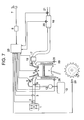
- FIG. 1 illustrates the structure of an apparatus for purifying and controlling exhaust gases which constitutes a typical embodiment of the present invention.
- FIG. 2 is a graph illustrating the NO x purification rate with the lapse of time in an experiment of alternately repeating rich driving (or running) and lean driving (or running) with the apparatus of the present invention.
- FIG. 3 is a graph illustrating the relation between NO x concentration and NO x purification rate in an exhaust gas.
- FIG. 4 is a graph illustrating NO x purification rate in the stoichiometric exhaust gas.
- FIG. 5 A and FIG. 5B are graphs illustrating the relation between the NO x concentration at the inlet of adsorption catalyst and the NO x concentration at the outlet of the adsorption catalyst at the time of change-over from a rich (stoichiometric) driving to a lean driving.
- FIG. 6 A and FIG. 6B are graphs illustrating the relation between the NO x concentration at the inlet of adsorption catalyst and the NO x concentration at the outlet of the adsorption catalyst at the time of change-over from a rich (stoichiometric) driving to a lean driving.
- FIG. 7 is an outlined view illustrating an engine controlling system.
- the above-mentioned problem of timing of the reduction treatment of NO x adsorbed on an NO x adsorption catalyst can be solved by carrying out the reduction treatment at the time when the quantity (or amount) of NO x calculated by subtracting the quantity (or amount) of NO x directly reduced to N 2 from the quantity (or amount) of NO x discharged (or exhausted) from an internal combustion engine has reached a predetermined amount, while having noticed a fact that the NO x adsorption catalyst reduce a part of No x to N 2 even in a lean driving.
- the reduction treatment of NO x can be started in a good timing for treating the exhaust gas, and therefore the level of exhaust gas can be maintained always under the value of regulation.
- an NO x adsorbing (or capturing) catalyst is provided in the exhaust gas passage (duct), said catalyst chemically adsorbing NO x from an exhaust gas in a state wherein, in the redox stoichiometric relation between components of exhaust gas, the quantity of oxidizing agent is larger than the quantity of reducing agent, and catalytically reducing the adsorbed NO x in a state wherein the quantity of reducing agent is not smaller than the quantity of oxidizing agent.
- the exhaust gas purification apparatus produces a state wherein, in a redox stoichiometric relation between the components of exhaust gas, the quantity of oxidizing agent is larger than the quantity of reducing agent and, in such a state, chemically adsorbs NO x on the adsorbing catalyst, and then produces a state wherein the quantity of reducing agent is not smaller than the quantity of oxidizing agent and, in such a state, contacts and reacts the NO x adsorbed on the adsorbing catalyst with the reducing agent and thereby reduces the NO x to harmless N 2 , and the apparatus further makes NO x harmless by its direct reduction to N 2 .
- adsorbing (or capturing) catalyst means a material having an ability of adsorbing substances such as NO x , etc. and at the same time having a catalytic function.
- the term means a material having an ability of adsorbing and capturing NO x , an ability of catalytically reducing NO x and an ability of catalytically oxidizing HC, CO, etc.
- the NO x adsorption catalyst used in the present invention adsorbs NO x in an exhaust gas during a lean driving as NO 2 on the adsorption catalyst, directly reduce a part of NO x to N 2 using HC, CO, etc. in the exhaust gas, and captures apart of NO x as NO 2 on the adsorption catalyst.
- the adsorbed and/or captured NO 2 is reduced to N 2 at a time of stoichiometric or rich A/F ratio.
- the adsorption catalyst contains K, Na, Mg, Sr, etc. as a base material for adsorbing NO x .
- the NO x adsorbing material is combined with Ti, Si, etc. to form a composite oxide.
- solid basicity an adsorption ability is controlled so as to adsorb and/or capture as NO 2 on the surface of the catalyst, thereby inhibiting absorption in the form of NO 3 — in the inner portion of the catalyst.
- oxidizing agent inclusively means O 2 , NO, NO 2 , etc. and especially means oxygen gas.
- reducing agent inclusively means HC supplied to an internal combustion engine, other HC as derivatives of the supplied HC, including oxygen-containing HC, which can be formed in the process of combustion, CO, H 2 , etc., and the reductive substances such as HC to be added to exhaust gas as a reductive component which will be mentioned later.
- the NO x in exhaust gas is separated from O 2 by adsorbing NO x from the lean exhaust gas by the use of the adsorption catalyst.
- the NO x adsorption catalyst used in the present invention in the next step, such a state wherein the quantity of reducing agent is equal to or larger than the quantity of oxidizing agent is produced in the redox system constituted of oxidizing agents (O 2 , NO x , etc.) and reducing agents (HC, CO, H 2 , etc.), and the NO x adsorbed on the adsorbing catalyst is contacted and reacted with the reducing agent such as HC to reduce the NO x to N 2 .
- the reducing agent such as HC to reduce the NO x to N 2 .
- the NO x in the exhaust gas comprises NO and NO 2 . Since NO 2 is higher than NO in reactivity, NO 2 can be adsorbed off and reduced more easily than NO. Accordingly, oxidation of NO to NO 2 makes it easier to adsorb off and reduce NO x in exhaust gas.
- the present invention includes, too, a technique of oxidizing NO x present in lean exhaust gas to NO 2 by the action of the coexisting O 2 and thereby removing the NO x , and the oxidizing means for this technique such as giving an NO-oxidizing function the adsorbing catalyst.
- the reduction reaction of the chemically adsorbed NO x can be approximately expressed by the following reaction formula:
- M is a metallic element. (The reason why MCO 3 is adopted as the reduced product is mentioned later.)
- the reaction mentioned above is an exothermic reaction. If an alkali metal (Na is adopted as its typical example) and an alkaline earth metal (Ba is adopted as its typical example) are adopted as the metal M, the heat of reaction in the normal state (1 atmosphere, 25° C.) can be calculated as follows:
- thermodynamic quantities of the adsorbed species the values of the corresponding solids are used.
- the heat of combustion of 5/9 mole of C 3 H 6 is 1,070 kilojoules, so that the heat of combustion of the reactions mentioned above can be said to be both comparable to the heat of combustion of HC. Naturally, this heat generated is transferred to the contacted exhaust gas, and local rise in temperature of the adsorbing catalyst surface can be avoided.
- the NO x -capturing agent is an NO x -absorbent
- the NO x captured in the bulk mass of absorbent is also reduced, due to which the generation of heat increases. Since the transfer of heat to the exhaust gas is limited, this generation of heat brings about a rise in temperature of the absorbent. This generation of heat shifts the equilibrium of the following absorbing reaction to the release side, wherein the left side is release side and the right side is absorption side.
- the adsorbing catalyst used in the present invention captures NO x only in the neighborhood of its surface.
- its heat of generation is small as an absolute value.
- the heat is rapidly transferred to the exhaust gas, so that the adsorbing catalyst shows only a small rise in temperature. Accordingly, release of the NO x once captured can be prevented satisfactorily.
- the NO x -adsorbing catalyst used in the present invention is characterized in that it captures NO x at surface thereof by a chemical adsorption and, in the step of reducing NO x , the generation of heat causes no release of NO x .
- the NO x adsorption catalyst used in the present invention is further characterized in that it captures NO x by a chemical adsorption at surface thereof or by chemical bond formation in the neighborhood of surface thereof and, in the step of reducing NO x , generation of heat causes no release of NO x .
- an NO x adsorption catalyst containing, as a part of its components, at least one element selected from the group consisting of potassium (K), sodium (Na), magnesium (Mg), strontium (Sr) and calcium (Ca).
- the exhaust gas purification apparatus for purifying exhaust gas of internal combustion engine to which the present invention is applied is provided in its exhaust gas duct (passage) with an NO x adsorption catalyst containing at least one element selected from the group consisting of potassium (K), sodium (Na), magnesium (Mg), strontium (Sr) and calcium (Ca) as a part of the components thereof, and it produces a state that, in a redox stoichiometric relation between the components of exhaust gas, the quantity of oxidizing agent is larger wherein the quantity of reducing agent and, in such a state, chemically adsorbs NO x on the NO x adsorption catalyst, and then produces a state wherein the quantity of reducing agent is not smaller than the quantity of oxidizing agent and, in such a state, contacts and reacts the NO x adsorbed on the catalyst with a reducing agent to reduce the NO x to harmless N 2 .
- K potassium
- Na sodium
- Mg magnesium
- Ca calcium
- the exhaust gas purification apparatus for purifying exhaust gas of internal combustion engine to which the present invention is applied is provided in the exhaust gas duct with an NO x adsorption catalyst containing at least one elements selected from the group consisting of potassium (K), sodium (Na), magnesium (Mg), strontium (sr) and calcium (Ca) as a part of the components thereof, and it produces a state wherein, in a redox stoichiometric relation between the components of exhaust gas, the quantity of oxidizing agent such as O 2 , etc. is larger than the quantity of reducing agent such as HC, etc.
- compositions comprising metals and metal oxides (or composite oxides) containing at least one element selected from the group consisting of potassium (K), sodium (Na), magnesium (Mg), strontium (Sr) and calcium (Ca), at least one member selected such as consisting of cerium, etc. and at least one element selected from noble metals such as platinum, rhodium, palladium, etc.; and a composition prepared by supporting the above-mentioned composition on a porous, heat-resistant metallic oxide.
- K potassium
- Na sodium
- Mg magnesium
- Sr strontium
- Ca calcium
- noble metals such as platinum, rhodium, palladium, etc.
- compositions have an excellent NO x -adsorbing performance and, in addition, an excellent SO x resistance.
- the state wherein the quantity of reducing agent is not smaller than the quantity of oxidizing agent can be produced by the following method.
- the condition of combustion is adjusted to a theoretical air-fuel ratio or a fuel-rich ratio.
- a reducing agent is added to a lean burn exhaust gas.
- the former can be achieved by the following method:
- This method includes a method of bringing a part of the multiple cylinders into a fuel-excess state and bringing the remainder into a fuel-deficient state and thereby producing a state that the quantity of reducing agent is not smaller than the quantity of oxidizing agent in the redox stoichiometric relation of the component of mixed exhaust gas discharged from whole cylinders.
- a method of adding a reducing agent to the upstream zone of the adsorbing catalyst in the exhaust gas stream a reducing agent
- gasoline, light oil, kerosene, natural gas and modified products thereof which are used as a fuel of the internal combustion engine, as well as hydrogen, alcohol, ammonia, etc. can be used.
- a method of leading blow-by gas or canister purge gas to the upstream zone of adsorbing catalyst and adding the reducing agent present in these gases such as hydrocarbon or the like into the zone is also an effective method.
- a fuel direct injection type internal combustion engine it is effective to inject fuel in the gas discharging stroke and throw a fuel as a reducing agent.
- the adsorption catalyst used in the present invention can be used in a variety of forms.
- the usable forms include a honeycomb form prepared by coating a honeycomb structure made of a metallic material such as cordierite, stainless steel or the like with an adsorbing catalyst component, as well as pellet-form, plate form, granular form, and powdery form.
- the timing for producing a state wherein the quantity of reducing agent is not smaller than the quantity of oxidizing agent can be decided according to the following methods, provided that the fundamental condition is to carry out the reduction treatment when the quantity of adsorbed NO x calculated by subtracting the quantity of NO x directly reduced to N 2 from the quantity of NO x discharged from the internal combustion engine has reached a predetermined amount:
- NO x purification rate being estimated from at least one quantity of state selected from the quantity of NO x adsorbed on NO x adsorption catalyst; the temperature of exhaust gas; the temperature of the adsorbing catalyst; the quantity of sulfur poisoning the catalyst; the driving distance of automobile; the degree of deterioration of the catalyst; the air/fuel ratio; the concentration of non-burnt hydrocarbon; NO x concentration on the catalyst, the time of lean driving measured from the point in time of changing the driving at theoretical air/fuel ratio or a rich driving to the lean driving; the rotational frequency (or rotation number) of internal combustion engine; the load of the engine; the quantity (or amount) of air inlet into the engine; and the quantity (or amount) of exhaust gas.
- the period of time during which the state wherein the quantity of reducing agent is not smaller than the quantity of oxidizing agent is maintained or the quantity of reducing agent which should be used for the purpose of maintaining said state can be determined previously by taking the characteristics of the adsorbing catalyst and the dimensions and characteristics of the internal combustion engine into account.
- Such conditions can be realized by increasing the quantity of fuel injected from the injection valve into the cylinders, or by supplying the fuel into the cylinders during the expanding stroke of the internal combustion engine or by supplying the fuel into the exhaust gas pipe.
- the explanation is mainly made as to the use of the NO x adsorption catalyst.
- the present invention can also be applied to a system using an NO x catalyst, wherein the NO x catalyst can not only capture a part of NO x in the exhaust gas during a lean driving, but also directly reduce a part of NO x in the exhaust gas using HC and CO in the exhaust gas, and reduce the captured NO x to N 2 at a time of stoichiometric or rich A/F ratio.
- the decision of timing of reduction treatment of NO x can be made, as in the case of using the NO x absorption catalyst, not-depending on the simple accumulation of generated amount of No x , but depending on the NO x captured amount obtained by subtracting the amount of NO x directly redxuced to N 2 during the lean burn state from the amount of NO x discharged from the internal combustion engine.
- the present invention also provides an exhaust gas purification apparatus for use in a lean burn internal combustion engine comprising:
- an NO x capturing catalyst disposed in said exhaust gas duct, said catalyst being able to capture a part of NO x in the exhaust gas in a lean burn state wherein the amount of an oxidizing agent is larger than the amount of a reducing agent in a redox stoichiometric relation of components in the exhaust gas and to catalytically reduce NO x captured by the catalyst in a state wherein the amount of the reducing agent is equal to or larger than the amount of the oxidizing agent, and
- a control apparatus which decides a timing for producing a state wherein the amount of the reducing agent is equal to or larger than the amount of the oxidizing agent, and carries out reduction treatment of the NO x captured by the catalyst by catalytical reaction with the reducing agent to form harmless N 2 , when the NO x captured amount reaches a predetermined amount, which is calculated from the NO x amount obtained by subtracting the amount of NO x directly reduced to N 2 during the lean burn state from the amount of NO x discharged from the internal combustion engine.
- An exhaust gas purification apparatus for use in a lean burn internal combustion engine comprising:
- an NO x adsorption catalyst disposed in said exhaust gas duct, said adsorption catalyst being able to chemically adsorb a part of NO x in the exhaust gas in a lean burn state wherein the amount of an oxidizing agent is larger than the amount of a reducing agent in a redox stoichiometric relation of components in the exhaust gas and to catalytically reduce NO x adsorbed on the catalyst in a state wherein the amount of the reducing agent is equal to or larger than the amount of the oxidizing agent, and
- a control apparatus which decides a timing for producing a state wherein the amount of the reducing agent is equal to or larger than the amount of the oxidizing agent, and carries out reduction treatment of the NO x adsorbed on the adsorption catalyst by catalytical reaction with the reducing agent to form harmless N 2 , when the NO x adsorbed amount reaches a predetermined amount, which is calculated from the NO x amount obtained by subtracting the amount of NO x directly reduced to N 2 during the lean burn state from the amount of NO x discharged from the internal combustion engine.
- An exhaust gas purification apparatus for use in a lean burn internal combustion engine comprising:
- an NO x adsorption catalyst disposed in said exhaust gas duct, said adsorption catalyst containing as apart of catalyst components at least one element selected from the group consisting of potassium, sodium, magnesium, strontium and calcium, and being able to chemically adsorb a part of NO x in the exhaust gas in a lean burn state wherein the amount of an oxidizing agent is larger than the amount of a reducing agent in a redox stoichiometric relation of components in the exhaust gas and to catalytically reduce NO x adsorbed on the catalyst in a state wherein the amount of the reducing agent is equal to or larger than the amount of the oxidizing agent, and
- a control apparatus which decides a timing for producing a state wherein the amount of the reducing agent is equal to or larger than the amount of the oxidizing agent, and carries out reduction treatment of the NO x adsorbed on the adsorbing catalyst by catalytical reaction with the reducing agent to form harmless N 2 , when the NO x adsorbed amount reaches a predetermined amount, which is calculated from the NO x amount obtained by subtracting the amount of NO x directly reduced to N 2 during the lean burn state from the amount of NO x discharged from the internal combustion engine.
- An exhaust gas purification apparatus for use in a lean burn internal combustion engine comprising:
- an NO x adsorption catalyst disposed in said exhaust gas duct, said adsorption catalyst containing as a part of catalyst components at least one element selected from the group consisting of potassium, sodium, magnesium, strontium and calcium, and being able to capture a part of NO x by chemical bonding in the exhaust gas on a surface and near the surface of the adsorption catalyst in a lean burn state wherein the amount of an oxidizing agent including an oxygen gas is larger than the amount of a reducing agent including a hydrocarbon in a redox stoichiometric relation of components in the exhaust gas, and to catalytically reduce NO x captured on the catalyst in a state wherein the amount of the reducing agent is equal to or larger than the amount of the oxidizing agent, and
- a control apparatus which decides a timing for producing a state wherein the amount of the reducing agent is equal to or larger than the amount of the oxidizing agent, and carries out reduction treatment of the NO x captured on the adsorbing catalyst by catalytical reaction with the reducing agent to form harmless N 2 , when the NO x captured amount reaches a predetermined amount, which is calculated from the NO x amount obtained by subtracting the amount of NO x directly reduced to N 2 during the lean burn state from the amount of NO x discharged from the internal combustion engine.
- adsorption catalyst is a composition comprising metals and metal oxides or composite oxides containing at least one element selected from the group consisting of potassium (K), sodium (Na), magnesium (Mg), strontium (Sr) and calcium (Ca); at least one element selected from rare earth elements such as cerium and the like; and at least one element selected from noble metals such as platinum, rhodium, palladium and the like, or said composition supported on a porous, heat-resistant metal oxide.
- adsorbing catalyst is a composition comprising metals and metal oxides or composite oxides containing at least one element selected from the group consisting of potassium (K), sodium (Na), magnesium (Mg), strontium (Sr) and calcium (Ca); at least one element selected from rare earth elements such as cerium and the like; at least one element selected from noble metals such as platinum, rhodium, palladium and the like; and at least one element selected from the group consisting of titanium and silicon, or said composition supported on a porous, heat-resistant metal oxide.
- Embodiment [VIII] An apparatus as mentioned in Embodiment [VIII], wherein the control of output torque is carried out by changing at least one factor selected from a time of ignition, a quantity (or amount) of inlet air, a quantity (or amount) of exhaust gas to be mixed into suction gas of internal combustion engine (EGR ratio), a quantity (or amount) of injected fuel, a timing of fuel injection, an electromotive motor assisting the internal combustion engine, a load of dynamo provided in the engine, and breaking in the output side of the engine.
- EGR ratio suction gas of internal combustion engine
- Characteristic properties of N-N9 containing Na as alkali metal and N-K9 containing K as alkali metal are as follows.
- Adsorption Catalyst N-N9 was Prepared by the Following Method.
- a nitric acid-acidified alumina slurry was prepared by agitating an alumina sol as a binder which was obtained by nitric acid-peptization of alumina powder and boehmite.
- the coating fluid thus obtained was dipped a honeycomb structure, and then the structure was immediately taken out. After removing the fluid kept in the cells by means of air blow, the coated structure was dried and calcined at 450° C. This procedure was repeated until the quantity of alumina coating had reached 150 g per liter of the apparent volume of the honeycomb. Then, active components of catalyst were supported on the alumina-coated honeycomb to obtain a honeycomb-form adsorbing catalyst.
- a honeycomb structure was impregnated with a solution of cerium nitrate (Ce nitrate), dried and then calcined at 600° C. for one hour. Subsequently, it was calcined with a mixed solution containing a solution of sodium nitrate (Na nitrate), a titania sol solution and a solution of magnesium nitrate (Mg nitrate), and dried and calcined in the same manner as above. Further, it was impregnated with a mixed solution containing dinitrodiamine Pt nitrate solution and a solution of rhodium nitrate (Rh nitrate) and calcined at 450° C. for one hour.
- Ce nitrate cerium nitrate
- Mg nitrate magnesium nitrate
- honeycomb-form adsorbing catalyst supporting Ce, Mg, Na, Ti, Rh and Pt on alumina Al 2 O 3
- 2Mg-(0.2Rh, 2.7Pt)-(18Na, 4Ti, 2Mg)-27Ce/Al 2 O 3 the expression “/Al 2 O 3 ” means that the active components are supported on Al 2 O 3
- the numerical figures preceding the symbols of elements express the weight (g) of each metallic component supported per liter of apparent volume of the honeycomb.
- the order of expression indicates the order of supporting.
- each component written closely to Al 2 O 3 is supported before another component written at a longer distance from Al 2 O 3 , and the components written in one parenthesis are supported simultaneously.
- the quantity of each component to be supported can be varied by changing the concentration of active component in the impregnating solution.
- N-N9 The procedure for preparing the adsorption catalyst N-N9 was repeated, except that the solution of Na nitrate used in the preparation of N-N9 was replaced by a solution of potassium nitrate (K nitrate).
- K nitrate potassium nitrate
- N-K9 namely 2Mg-(0.2Rh, 2.7Pt)-(18K, 4Ti, 2Mg)-27Ce/Al 2 O 3 .
- the adsorption catalysts obtained above were heat-treated at 700° C. for 5 hours in an oxidative atmosphere, and their characteristic properties were tested in the following manner.
- a honeycomb-form adsorbing catalyst having a volume of 1.7 L prepared according to the method of the present invention was mounted on a passenger car equipped with a lean burn-specification gasoline engine having a displacement of 1.8 L, and the NO x -cleaning characteristics were evaluated.
- the lowered purification rate was recovered to 100% by the rich driving for 30 seconds and the injection of fuel in the cylinder in the expanding stroke or gas-discharging stroke of the engine. Then, a lean driving was carried out again, and the NO x purification ability was recovered and the NO x purification rate dropped in the same manner as above.
- the lean driving and rich driving were repeated multiple times, the decreasing velocity of NO x purification rate in the period of lean driving varied depending on the temperature of catalyst, the quantity of poisoning sulfur, the driving distance of automobile, the NO x concentration at inlet of catalyst, and the quantity of exhaust gas. Accordingly, it is important to estimate the NO x purification rate with high accuracy in accordance with the condition of driving.
- FIG. 3 illustrates the relation between NO x concentration and NO x purification rate of lean exhaust gas. It is apparent that NO x purification rate decreases with time, the decreasing velocity is smaller at a lower NO x concentration. Even after the time when the quantity of adsorbed NO x is considered to have reached saturation, NO x purification rate is maintained at a level of 22-25%, demonstrating that a portion of NO x is directly reduced to N 2 .
- the quantities of NO x captured by the time when the NO x purification rate reaches 50% and 30%, respectively, calculated from FIG. 3 are shown in Table 1.
- the quantity of captured NO x is approximately constant regardless of NO x concentration. It is a characteristic feature of chemical adsorption that the quantity of adsorption is independent of the concentration (pressure) of the substance adsorbed.
- the substance which can be considered functioning as the adsorption medium first of all is Pt particles.
- the quantity of adsorbed CO at 100° C. was 4.5 ⁇ 1 ⁇ 4 mole. This value is equal to about ⁇ fraction (1/100) ⁇ of the above-mentioned NO x adsorption, demonstrating that Pt is not the main adsorbing medium.
- the BET specific surface area of this adsorption catalyst measured by the method of nitrogen adsorption on the bulk mixture on cordierite, was about 25 m 2 /g, which corresponded to a value of 28.050 m 2 per 1.7 L of honeycomb.
- a chemical investigation on the structure of Na in the adsorbing catalyst of the invention revealed that the Na existed as Na 2 CO 3 predominantly, based on the findings that the catalyst dissolved in mineral acids with evolution of CO 2 gas and that the value of inflection point on its neutralizing titration curve with mineral acid suggested it.
- Na 2 CO 3 has a specific gravity of 2.533 g/ml, from which the volume of one Na 2 CO 3 molecule can be calculated; if Na 2 CO 3 is assumed to have a cubic structure, the area of its one face can be calculated, which is taken as the area occupied by superficial Na 2 CO 3 ).
- 0.275 mole of Na 2 CO 3 has an ability of adsorbing 0.55 mole of NO 2 .
- the quantity of NO x actually removed by the adsorbing catalyst of the present invention was approximately 0.04 mole which is less than ⁇ fraction (1/10) ⁇ of the above-mentioned value.
- This difference is attributable to that the BET method evaluates the physical surface area and it takes the surface areas of the molecules other than Na 2 CO 3 such as Al 2 O 3 , also into account.
- the evaluation given above indicates that the quantity of adsorbed NO x is much smaller than the NO x -capturing ability of the Na 2 CO 3 bulk, and NO x is captured only on the Na 2 CO 3 surface or at least in a limited region in the vicinity of surface.
- FIG. 4 illustrates the NO x purification rate just after the change-over from lean driving to stoichiometric driving. It is apparent that the adsorbing catalyst of the present invention gives an NO x purification rate of 90% or above from just after the change-over to stoichiometric running (or driving).
- FIGS. 5A, 5 B and FIGS. 6A, 6 B illustrate the NO x purification characteristics before and after the change-over from lean running to stoichiometric or rich running.
- the NO x concentration in the exhaust gas of A/F 14.2 is so high that the inlet NO x concentration in the lean driving largely increases.
- the outlet NO x concentration is usually much lower than the inlet NO x concentration similarly to the case of FIG. 5A, and the outlet NO x concentration reaches approximately zero in a shorter period of time than in FIG. 5 A.
- the A/F value as a condition of regeneration exercises an influence upon the time required for regeneration.
- the A/F value, time and quantity of reducing agent suitable for regeneration are influenced by the composition, shape and temperature of adsorbing catalyst, the SV value, the kind of reducing agent, and the shape and length of exhaust gas passage. Accordingly, the conditions of regeneration should be decided with consideration of all these factors.
- the outlet NO x concentration is usually much lower than the inlet NO x concentration and regeneration of adsorbing catalyst progresses in a short period of time.
- FIG. 1 is an example of the apparatus for reducing NO x based on estimated quantity of adsorbed NO x according to the present invention.
- At least one quantity of state selected from the temperature of exhaust gas, the adsorption catalyst temperature, the vehicle speed, the air/fuel ratio, the rotation number of internal combustion engine, the load of the engine, the quantity of suction air (or intake air amount) and the quantity (or amount) of exhaust gas is input to the NO x discharge quantity-calculating part of the engine having the NO x -adsorption catalyst.
- the NO x discharge is multiplied by the residual NO x rate (proportion of residual NO x obtained by subtracting the quantity of NO x directly reduced to N 2 ) and the product is integrated over the time period of lean driving to determine the quantity of adsorbed NO x ( ⁇ Q NOx ).
- ⁇ Q NOx residual NO x rate
- the reduction treatment of NO x adsorbed on the NO x adsorption catalyst is carried out by increasing the concentration of non-burnt hydrocarbon in the exhaust gas flowing into the catalyst.
- this is realized by making the air/fuel ratio greater than the theoretical air/fuel ratio (namely, increasing the quantity of injected fuel) or, in the case of injection into cylinders, additionally injecting fuel in the expanding stroke or gas discharging stroke of the engine and thereby increasing the concentration of non-burnt hydrocarbon. Due to this increase, the NO x adsorbed on the NO x adsorption catalyst is reduced by the non-burnt hydrocarbon and made harmless.
- concentration of non-burnt hydrocarbon increases, there arises a possibility that the output torque of the engine or the final driving torque of the driving wheels can vary.
- This variation is prevented by changing any one factors selected from the group consisting of the ignition time, the quantity of inlet air, the quantity of exhaust gas to be mixed into inlet air of the internal combustion engine (EGR rate), the quantity of injected fuel, or the timing of fuel injection, or by controlling the electromotive motor assisting the output of internal combustion engine, the load of generator placed in the engine and the breaking of output side of the engine.
- FIG. 7 is a diagram illustrating the system for controlling the internal combustion engine to realize the condition mentioned above.
- the apparatus of the present invention is constituted of an exhaust gas system having an engine 99 which can be worked at a lean burn, an air flow sensor 2 , an air suction system having electronically controlled throttle valve 3 , etc., an oxygen concentration sensor (or A/F sensor) 19 , an exhaust gas temperature sensor 17 , an NO x adsorption catalyst 18 , etc. and a controlling unit (ECU) 25 .
- the ECU is constituted of I/O LSI as an input-output interface, a computing unit MPU, memory devices RAM and ROM remembering a number of controlling programs, a timer counter, etc.
- ECU houses a controlling program carrying out the treatment of the present invention mentioned below, and estimates the NO x purification rate, compares the estimated values, and reduces NO x on the basis of various sensor signals.
- the NO x purification rate estimating part of the NO x adsorption catalyst is input at least one quantity of state selected from the group consisting of the quantity of NO x adsorbed on NO x adsorption catalyst, the temperature of exhaust gas, the temperature of adsorbing catalyst, the quantity of poisoning sulfur, the driving distance of automobile, the extent of deterioration of catalyst, the air/fuel ratio, the concentration of non-burnt hydrocarbon, the NO x concentration before the catalyst, the period of lean driving having passed from the time of change-over from stoichiometric driving (driving at theoretical air/fuel ratio) or rich driving to lean driving, the rotation number of internal combustion engine, the load of the engine, the quantity of inlet air, and the quantity of exhaust gas.
- the reduction treatment of NO x is carried out.
- the reduction treatment of NO x adsorbed on the NO x adsorption catalyst is carried out by increasing the concentration of non-burnt hydrocarbon in the exhaust gas flowing into the catalyst. Concretely saying, this is realized by making the air/fuel ratio greater than the theoretical air/fuel ratio (namely, by increasing the quantity of injected fuel) or, in the case of injection into cylinders, by additionally injecting fuel in the expanding stroke or gas discharging stroke of the engine and thereby increasing the concentration of non-burnt hydrocarbon. Due to this increase, the NO x adsorbed on the NO x adsorption catalyst is reduced by the non-burnt hydrocarbon and made harmless.
- the output torque of the engine or the final driving torque of the driving wheels can vary. This variation is prevented by changing any one factors selected from the group consisting of the ignition time, the quantity of inlet air, the quantity of exhaust gas to be mixed into inlet air of the internal combustion engine (EGR rate, EGR valve), the quantity of injected fuel (injector 5 ), or the timing of fuel injection, or by controlling the electromotive motor assisting the output of internal combustion engine, the load of generator placed in the engine and the breaking of output side of the engine.
- the above-mentioned apparatus for purifying and controlling exhaust gas functions as follows. That is, the air inlet into engine is filtered by air cleaner 1 , measured by air flow sensor 2 , passes electronically controlled valve 3 , receives the fuel injected from injector 5 , and supplied to engine 99 as a mixed gas.
- the signals of the air flow sensor and other sensors are input to ECU (engine control unit) 25 .
- ECU evaluates the working state of internal combustion engine and state of NO x adsorption catalyst by the method mentioned later, determines the driving air/fuel ratio, controls the injection time of injector 5 , and thereby sets the fuel concentration in the mixed gas to the prescribed value. It is allowable to set the injector 5 so as to enable an injection into cylinders like in diesel engine, instead of setting it at the position of air suction boat of FIG. 7 . It is also allowable to set the fuel concentration in the mixed gas to the prescribed value by keeping the quantity of injected fuel constant and decreasing the quantity of inlet air by an opening control (throttle actuator) of the electronically controlled throttle valve 3 . The mixed gas inlet into cylinders is ignited with igniting plug 6 controlled by the signals of ECU 25 , and burns.
- the exhaust gas of the combustion is led to the exhaust gas purification system.
- the exhaust gas purification system is provided with NO x adsorption catalyst which, in the period of stoichiometric driving, purifys NO x , HC and CO in the exhaust gas by its ternary catalytic function and, in the period of lean driving, purifys NO x by its NO x -adsorbing function and at the same time purifys HC and CO by its burning function.
- the apparatus of the invention effectively purifys the exhaust gas under all the engine combustion conditions including lean driving and stoichiometric (including rich) driving.
- 7 is an accelerating pedal
- 8 is a load sensor
- 9 is a suction air temperature sensor
- 12 is a fuel pump
- 13 is a fuel tank
- 20 is an adsorption catalyst temperature sensor
- 21 is an exhaust gas temperature sensor
- 26 is a knock sensor (a knocking detecting sensor)
- 27 is EGR valve
- 28 is a water temperature sensor
- 29 is a crank angle sensor.
- the apparatus of the present invention is provided with an NO x adsorption catalyst having a function of directly reducing NO x to N 2 simultaneously, and the apparatus estimates the quantity of adsorbed NO x in a high accuracy and when the estimated value has exceeded a prescribed value, carries out a reduction treatment of the NO x adsorbed on the NO x adsorption catalyst, so that the apparatus of the present invention can purify NO x in a high efficiency over a long period of time without increasing the quantity of harmful exhaust gas.
Landscapes
- Engineering & Computer Science (AREA)
- Chemical & Material Sciences (AREA)
- Combustion & Propulsion (AREA)
- Mechanical Engineering (AREA)
- General Engineering & Computer Science (AREA)
- Chemical Kinetics & Catalysis (AREA)
- Exhaust Gas After Treatment (AREA)
- Exhaust Gas Treatment By Means Of Catalyst (AREA)
- Catalysts (AREA)
Applications Claiming Priority (2)
| Application Number | Priority Date | Filing Date | Title |
|---|---|---|---|
| JP11-224910 | 1999-08-09 | ||
| JP22491099A JP3613083B2 (ja) | 1999-08-09 | 1999-08-09 | 排気浄化制御装置 |
Publications (1)
| Publication Number | Publication Date |
|---|---|
| US6755015B1 true US6755015B1 (en) | 2004-06-29 |
Family
ID=16821083
Family Applications (1)
| Application Number | Title | Priority Date | Filing Date |
|---|---|---|---|
| US09/571,984 Expired - Fee Related US6755015B1 (en) | 1999-08-09 | 2000-05-16 | Apparatus for purifying and controlling exhaust gases |
Country Status (2)
| Country | Link |
|---|---|
| US (1) | US6755015B1 (ja) |
| JP (1) | JP3613083B2 (ja) |
Cited By (9)
| Publication number | Priority date | Publication date | Assignee | Title |
|---|---|---|---|---|
| US20060118345A1 (en) * | 2002-09-26 | 2006-06-08 | Toshihiro Fukumoto | Full hybrid electric car |
| US20070012027A1 (en) * | 2001-10-08 | 2007-01-18 | Yang Koon C | NOx control for an internal combustion engine |
| US20070199303A1 (en) * | 2004-02-17 | 2007-08-30 | Umicore Ag & Co. Kg | Method For Determining The Instant At Which A Nitrogen Oxide Storage Catalyst Is Switched From The Storage Phase To The Regeneration Phase And For Diagnosing The Storage Properties Of This Catalyst |
| US20080038603A1 (en) * | 2006-08-11 | 2008-02-14 | Samsung Sdi Co., Ltd. | Fuel processor having desulfurizer with sulfer sensor, fuel cell system including the fuel processor, and method of operating the fuel cell system |
| US20110047984A1 (en) * | 2009-08-31 | 2011-03-03 | Hyundai Motor Company | Exhaust system |
| US8142529B2 (en) | 2006-08-17 | 2012-03-27 | Samsung Sdi Co., Ltd. | Fuel processor having carbon monoxide removing unit and method of operating the same |
| WO2013116484A1 (en) | 2012-02-01 | 2013-08-08 | Intramicron, Inc. | Direct in situ monitoring of adsorbent and catalyst beds |
| US20140283504A1 (en) * | 2011-05-16 | 2014-09-25 | Toyota Jidosha Kabushiki Kaisha | Air-fuel ratio control device for internal combustion engine |
| US10746115B2 (en) * | 2018-02-07 | 2020-08-18 | Ford Global Technologies, Llc | Methods and systems for an exhaust gas treatment arrangement |
Families Citing this family (2)
| Publication number | Priority date | Publication date | Assignee | Title |
|---|---|---|---|---|
| JP5709184B2 (ja) * | 2013-08-19 | 2015-04-30 | 三菱重工業株式会社 | 排ガス浄化方法および排ガス浄化装置 |
| JP2016205146A (ja) * | 2015-04-15 | 2016-12-08 | 本田技研工業株式会社 | 内燃機関の排気浄化装置 |
Citations (10)
| Publication number | Priority date | Publication date | Assignee | Title |
|---|---|---|---|---|
| US5437153A (en) | 1992-06-12 | 1995-08-01 | Toyota Jidosha Kabushiki Kaisha | Exhaust purification device of internal combustion engine |
| US5450722A (en) * | 1992-06-12 | 1995-09-19 | Toyota Jidosha Kabushiki Kaisha | Exhaust purification device of internal combustion engine |
| US5595060A (en) | 1994-05-10 | 1997-01-21 | Mitsubishi Jidosha Kogyo Kabushiki Kaisha | Apparatus and method for internal-combustion engine control |
| US5657625A (en) | 1994-06-17 | 1997-08-19 | Mitsubishi Jidosha Kogyo Kabushiki Kaisha | Apparatus and method for internal combustion engine control |
| WO1997047864A1 (en) | 1996-06-10 | 1997-12-18 | Hitachi, Ltd. | Exhaust gas purification apparatus of internal combustion engine and catalyst for purifying exhaust gas of internal combustion engine |
| US5715679A (en) * | 1995-03-24 | 1998-02-10 | Toyota Jidosha Kabushiki Kaisha | Exhaust purification device of an engine |
| US5771686A (en) * | 1995-11-20 | 1998-06-30 | Mercedes-Benz Ag | Method and apparatus for operating a diesel engine |
| US5839275A (en) * | 1996-08-20 | 1998-11-24 | Toyota Jidosha Kabushiki Kaisha | Fuel injection control device for a direct injection type engine |
| US5884476A (en) * | 1996-09-09 | 1999-03-23 | Toyota Jidosha Kabushiki Kaisha | Exhaust gas purifying device for engine |
| US5974788A (en) * | 1997-08-29 | 1999-11-02 | Ford Global Technologies, Inc. | Method and apparatus for desulfating a nox trap |
-
1999
- 1999-08-09 JP JP22491099A patent/JP3613083B2/ja not_active Expired - Fee Related
-
2000
- 2000-05-16 US US09/571,984 patent/US6755015B1/en not_active Expired - Fee Related
Patent Citations (10)
| Publication number | Priority date | Publication date | Assignee | Title |
|---|---|---|---|---|
| US5437153A (en) | 1992-06-12 | 1995-08-01 | Toyota Jidosha Kabushiki Kaisha | Exhaust purification device of internal combustion engine |
| US5450722A (en) * | 1992-06-12 | 1995-09-19 | Toyota Jidosha Kabushiki Kaisha | Exhaust purification device of internal combustion engine |
| US5595060A (en) | 1994-05-10 | 1997-01-21 | Mitsubishi Jidosha Kogyo Kabushiki Kaisha | Apparatus and method for internal-combustion engine control |
| US5657625A (en) | 1994-06-17 | 1997-08-19 | Mitsubishi Jidosha Kogyo Kabushiki Kaisha | Apparatus and method for internal combustion engine control |
| US5715679A (en) * | 1995-03-24 | 1998-02-10 | Toyota Jidosha Kabushiki Kaisha | Exhaust purification device of an engine |
| US5771686A (en) * | 1995-11-20 | 1998-06-30 | Mercedes-Benz Ag | Method and apparatus for operating a diesel engine |
| WO1997047864A1 (en) | 1996-06-10 | 1997-12-18 | Hitachi, Ltd. | Exhaust gas purification apparatus of internal combustion engine and catalyst for purifying exhaust gas of internal combustion engine |
| US5839275A (en) * | 1996-08-20 | 1998-11-24 | Toyota Jidosha Kabushiki Kaisha | Fuel injection control device for a direct injection type engine |
| US5884476A (en) * | 1996-09-09 | 1999-03-23 | Toyota Jidosha Kabushiki Kaisha | Exhaust gas purifying device for engine |
| US5974788A (en) * | 1997-08-29 | 1999-11-02 | Ford Global Technologies, Inc. | Method and apparatus for desulfating a nox trap |
Cited By (16)
| Publication number | Priority date | Publication date | Assignee | Title |
|---|---|---|---|---|
| US20070012027A1 (en) * | 2001-10-08 | 2007-01-18 | Yang Koon C | NOx control for an internal combustion engine |
| US20060118345A1 (en) * | 2002-09-26 | 2006-06-08 | Toshihiro Fukumoto | Full hybrid electric car |
| US20070199303A1 (en) * | 2004-02-17 | 2007-08-30 | Umicore Ag & Co. Kg | Method For Determining The Instant At Which A Nitrogen Oxide Storage Catalyst Is Switched From The Storage Phase To The Regeneration Phase And For Diagnosing The Storage Properties Of This Catalyst |
| US7735312B2 (en) * | 2004-02-17 | 2010-06-15 | Umicor Ag & Co. Kg | Method for determining the instant at which a nitrogen oxide storage catalyst is switched from the storage phase to the regeneration phase and for diagnosing the storage properties of this catalyst |
| US20100307136A1 (en) * | 2004-02-17 | 2010-12-09 | Umicore Ag & Co. Kg | Method For Determining The Instant At Which A Nitrogen Oxide Storage Catalyst Is Switched From The Storage Phase To The Regeneration Phase And For Diagnosing The Storage Properties Of This Catalyst |
| US8341938B2 (en) | 2004-02-17 | 2013-01-01 | Umicore Ag & Co. Kg | Method for determining the instant at which a nitrogen oxide storage catalyst is switched from the storage phase to the regeneration phase and for diagnosing the storage properties of this catalyst |
| US20080038603A1 (en) * | 2006-08-11 | 2008-02-14 | Samsung Sdi Co., Ltd. | Fuel processor having desulfurizer with sulfer sensor, fuel cell system including the fuel processor, and method of operating the fuel cell system |
| US8226736B2 (en) * | 2006-08-11 | 2012-07-24 | Samsung Sdi Co., Ltd. | Fuel processor having desulfurizer with sulfer sensor, fuel cell system including the fuel processor, and method of operating the fuel cell system |
| US8142529B2 (en) | 2006-08-17 | 2012-03-27 | Samsung Sdi Co., Ltd. | Fuel processor having carbon monoxide removing unit and method of operating the same |
| EP2295751A1 (en) * | 2009-08-31 | 2011-03-16 | Hyundai Motor Company | Exhaust system |
| US20110047984A1 (en) * | 2009-08-31 | 2011-03-03 | Hyundai Motor Company | Exhaust system |
| US20140283504A1 (en) * | 2011-05-16 | 2014-09-25 | Toyota Jidosha Kabushiki Kaisha | Air-fuel ratio control device for internal combustion engine |
| US9212583B2 (en) * | 2011-05-16 | 2015-12-15 | Toyota Jidosha Kabushiki Kaisha | Air-fuel ratio control device for internal combustion engine |
| WO2013116484A1 (en) | 2012-02-01 | 2013-08-08 | Intramicron, Inc. | Direct in situ monitoring of adsorbent and catalyst beds |
| US10175213B2 (en) | 2012-02-01 | 2019-01-08 | Intramicron, Inc. | Direct in situ monitoring of adsorbent and catalyst beds |
| US10746115B2 (en) * | 2018-02-07 | 2020-08-18 | Ford Global Technologies, Llc | Methods and systems for an exhaust gas treatment arrangement |
Also Published As
| Publication number | Publication date |
|---|---|
| JP3613083B2 (ja) | 2005-01-26 |
| JP2001050036A (ja) | 2001-02-23 |
Similar Documents
| Publication | Publication Date | Title |
|---|---|---|
| KR100290272B1 (ko) | 내연기관의 배기 가스 정화 장치 및 내연기관의 배기 가스 정화촉매 | |
| US6755015B1 (en) | Apparatus for purifying and controlling exhaust gases | |
| US20020050135A1 (en) | Apparatus for purifying and controlling exhaust gases | |
| JP4464472B2 (ja) | 内燃機関の排ガス浄化方法及び浄化装置 | |
| JP4027555B2 (ja) | 内燃機関の排ガス浄化装置 | |
| JP4147702B2 (ja) | 内燃機関の排ガス浄化用NOx吸着触媒 | |
| JPH11169708A (ja) | 内燃機関の排ガス浄化装置 | |
| JP3896223B2 (ja) | 内燃機関の排ガス浄化装置 | |
| JP3896224B2 (ja) | 内燃機関の制御装置 | |
| JPH11190210A (ja) | 排ガス浄化制御装置 | |
| JP3107303B2 (ja) | 内燃機関の排ガス浄化装置 | |
| AU742434B2 (en) | Exhaust gas purification apparatus of internal combustion engine and catalyst for purifying exhaust gas of internal combustion engine | |
| JP2001050033A (ja) | 排気浄化制御装置 | |
| JP2002115534A (ja) | 内燃機関の排ガス浄化装置 | |
| JPH1181987A (ja) | NOxの浄化方法 |
Legal Events
| Date | Code | Title | Description |
|---|---|---|---|
| AS | Assignment |
Owner name: HITACHI, LTD., JAPAN Free format text: ASSIGNMENT OF ASSIGNORS INTEREST;ASSIGNOR:MANAKA, TOSHIO;REEL/FRAME:010835/0290 Effective date: 20000411 |
|
| FEPP | Fee payment procedure |
Free format text: PAYOR NUMBER ASSIGNED (ORIGINAL EVENT CODE: ASPN); ENTITY STATUS OF PATENT OWNER: LARGE ENTITY |
|
| FPAY | Fee payment |
Year of fee payment: 4 |
|
| FEPP | Fee payment procedure |
Free format text: PAYOR NUMBER ASSIGNED (ORIGINAL EVENT CODE: ASPN); ENTITY STATUS OF PATENT OWNER: LARGE ENTITY Free format text: PAYER NUMBER DE-ASSIGNED (ORIGINAL EVENT CODE: RMPN); ENTITY STATUS OF PATENT OWNER: LARGE ENTITY |
|
| REMI | Maintenance fee reminder mailed | ||
| LAPS | Lapse for failure to pay maintenance fees | ||
| STCH | Information on status: patent discontinuation |
Free format text: PATENT EXPIRED DUE TO NONPAYMENT OF MAINTENANCE FEES UNDER 37 CFR 1.362 |
|
| FP | Lapsed due to failure to pay maintenance fee |
Effective date: 20120629 |