US6744482B2 - Active matrix type liquid crystal display device having particular positioning reference pattern and fabrication method thereof - Google Patents
Active matrix type liquid crystal display device having particular positioning reference pattern and fabrication method thereof Download PDFInfo
- Publication number
- US6744482B2 US6744482B2 US10/119,362 US11936202A US6744482B2 US 6744482 B2 US6744482 B2 US 6744482B2 US 11936202 A US11936202 A US 11936202A US 6744482 B2 US6744482 B2 US 6744482B2
- Authority
- US
- United States
- Prior art keywords
- common electrode
- liquid crystal
- layer
- display device
- crystal display
- Prior art date
- Legal status (The legal status is an assumption and is not a legal conclusion. Google has not performed a legal analysis and makes no representation as to the accuracy of the status listed.)
- Expired - Lifetime, expires
Links
Images


Classifications
-
- G—PHYSICS
- G02—OPTICS
- G02F—OPTICAL DEVICES OR ARRANGEMENTS FOR THE CONTROL OF LIGHT BY MODIFICATION OF THE OPTICAL PROPERTIES OF THE MEDIA OF THE ELEMENTS INVOLVED THEREIN; NON-LINEAR OPTICS; FREQUENCY-CHANGING OF LIGHT; OPTICAL LOGIC ELEMENTS; OPTICAL ANALOGUE/DIGITAL CONVERTERS
- G02F1/00—Devices or arrangements for the control of the intensity, colour, phase, polarisation or direction of light arriving from an independent light source, e.g. switching, gating or modulating; Non-linear optics
- G02F1/01—Devices or arrangements for the control of the intensity, colour, phase, polarisation or direction of light arriving from an independent light source, e.g. switching, gating or modulating; Non-linear optics for the control of the intensity, phase, polarisation or colour
- G02F1/13—Devices or arrangements for the control of the intensity, colour, phase, polarisation or direction of light arriving from an independent light source, e.g. switching, gating or modulating; Non-linear optics for the control of the intensity, phase, polarisation or colour based on liquid crystals, e.g. single liquid crystal display cells
- G02F1/133—Constructional arrangements; Operation of liquid crystal cells; Circuit arrangements
- G02F1/1333—Constructional arrangements; Manufacturing methods
- G02F1/1343—Electrodes
- G02F1/134309—Electrodes characterised by their geometrical arrangement
- G02F1/134363—Electrodes characterised by their geometrical arrangement for applying an electric field parallel to the substrate, i.e. in-plane switching [IPS]
Definitions
- the present invention relates to a liquid crystal display device and a fabrication method thereof and, particularly, to an IPS (In-Plane Switching) mode active matrix type liquid crystal display device and a fabrication method thereof.
- IPS In-Plane Switching
- An active matrix type liquid crystal display device (referred to as “AMLCD”, hereinafter), which uses TFT's (Thin Film Transistors) as pixel switching elements, can provide a high image quality and has been used as a display device of a portable type computer and, particularly, as a monitor of a compact desk-top computer recently.
- AMLCD Active matrix type liquid crystal display device
- the AMLCD is roughly classified to a type in which a display is performed by rotating a direction of molecular axis of oriented liquid crystal molecule, which is called “director”, in a plane orthogonal to a substrate thereof and a type in which a display is performed by rotating the director in a plane parallel to the substrate.
- a liquid crystal display device of the TN (Twisted Nematic) mode is a typical example of the former type and that of the IPS (In-Plane Switching) mode is a typical example of the latter type.
- a patterning on a substrate is performed by photolithography using a photo mask.
- the stepper exposure is performed in the display region within the substrate, it is required, in laminating patterned layers in the display region, to precisely pattern an underlying layer in a vertical direction in every shot and to make an error of overlapped area between adjacent exposure shots as small as possible in a horizontal direction in every exposing shot.
- the IPS mode AMLCD has the merit of wide viewing angle while has a demerit of small area of a aperture of a pixel region. Therefore, the demand of a technique for increasing the area of the aperture has become technological recently.
- JP H07-036058 A An example of the IPS mode liquid crystal display device is disclosed in JP H07-036058 A (referred to as “prior art 1”, hereinafter).
- the IPS mode liquid crystal display device disclosed in the prior art 1 is constructed with a TFT array substrate, scanning lines formed on the substrate, which is formed firstly, a common electrode formed in a metal layer, which is in the same layer of the scanning lines, signal lines (referred to as “data lines”, hereinafter) formed between the common electrode and an insulating film and pixel electrodes formed in the same layer of the data lines.
- IPS mode liquid crystal display device is disclosed in U.S. Pat. No. 6,069,678 (corresponding to JP H10-186407 A and referred to as “prior art 2”, hereinafter).
- a common electrode is formed in an uppermost layer in lieu of the same layer as the initially formed scanning lines.
- a pattern exposure for a substrate is performed by dividing the pattern as shown in FIG. 1 .
- the size of a transparent insulating substrate is constituted with zones 37 Z
- zones 1 Z to 20 Z arranged in a peripheral portion form a peripheral terminal portion for inputting voltages to a display region and the display region as a liquid crystal display is formed by zones 21 Z to 36 Z within an area defined by a thick solid line.
- FIG. 2 shows a case where only the exposure shot in the zone 21 Z is deviated rightward with respect to a gate layer.
- FIG. 3A shows an ideally arranged pattern of a layout in the vicinity of a unit TFT element. As shown in FIG. 3A, an interlayer insulating film is formed on a scanning line 28 forming a first wiring layer and a common electrode wiring portion 26 a and, on the interlayer insulating film, data lines 24 forming a second wiring layer and a pixel auxiliary electrode 35 are formed.
- an amorphous silicon layer 29 is formed on the scanning line 28 and a drain electrode 30 a connected to the data line 24 and a source electrode 30 b connected to the pixel auxiliary electrode 35 are formed on the amorphous silicon layer 29 .
- FIG. 3B shows a case where the pattern of the data line, the drain electrode and the pixel auxiliary electrode is deviated in the rightward direction.
- the scanning line 28 gate line
- areas of the drain electrode and the source electrode, which are overlapped with the amorphous silicon layer 29 are reduced. Therefore, write characteristics and holding characteristics of the TFT, which is formed by the exposure shot of the zone 21 Z, with respect to voltage applied to liquid crystal of the TFT are varied. Therefore, a display state becomes uneven since only the region in which the exposure shots are deviated becomes dark as shown in FIG. 5, comparing with a uniform display state of a liquid crystal display device having no overlapping deviation between adjacent exposure shots shown in FIG. 4 .
- the second (second wiring layer) and subsequent exposures to be performed subsequent to an exposure of the first layer (first wiring layer), which is performed on absolute position with high precision, must be performed as mentioned below.
- a test exposure is performed by detecting an alignment marker formed in the first layer and, on the basis of the detected alignment marker as a reference, programming the exposure such that a designed overlapping with the pattern of the first layer is obtained.
- the present invention was made in view of these problems and an object of the present invention is to provide an active matrix type liquid crystal display device, which can excludes the problems of the prior art display device.
- Another object of the present invention is to provide a manufacturing method for manufacturing the active matrix type liquid crystal display device.
- the present invention is featured by that a region having sides extending in a wiring direction of a second wiring layer is formed of a material forming a first wiring layer (underlying wiring layer) in the same time as the time in which the first wiring layer is formed.
- a first electrically conductive layer which constitutes scanning lines each extending over a plurality of pixel regions and a common electrode wiring, is formed on one of the substrate pair, which is an active element side substrate on which switching elements such as TFT's are formed.
- Positioning reference pattern regions each extending in a direction crossing an extending direction of the scanning lines are formed in the first conductive layer.
- a plurality of switching elements are formed on the active element substrate correspondingly to a plurality of pixel regions related to the scanning lines.
- a second electrically conductive layer constituting data lines each extending over a plurality of pixel regions related to the plurality of the switching elements is formed simultaneously with the formation of the electrodes of the switching elements and the extending direction of the data line is positioned such that it coincident with an extending direction of the positioning reference pattern regions.
- a third electrically conductive layer constituting the pixel electrodes and the common electrode is formed on the side of the uppermost layer (close to the liquid crystal layer) and the pixel electrodes are electrically connected to the respective switching elements through contact-holes.
- the common electrode is formed of a transparent electrode material and the data lines except portions thereof in the vicinity of the scanning lines are positioned within width of the common electrode.
- the positioning reference pattern region has at least one of a protruded portion and a recessed portion provided in at least one of a portion of the common electrode wiring and a portion of the scanning line.
- the common electrode and the pixel electrodes are formed of the same material and the common electrode is electrically connected to the common electrode wiring through contact-holes provided in an insulating layer between the first electrically conductive layer and the third electrically conductive layer in every pixel region.
- a black matrix layer having width smaller than the width of the common electrode covering the data line is formed in a position opposing to the data line on the opposing substrate opposing the active element substrate such that a light shielding film does not exist between the common electrode covering the data line and the pixel electrode adjacent to the common electrode in a plan view.
- the positioning reference patter region when the positioning reference patter region is the protruded or recessed portion, the positioning reference pattern regions are arranged on both sides of the data line.
- the width of the protruded or recessed portion as the positioning reference pattern region in a direction orthogonal to the data line is preferably not smaller than 2 ⁇ m and not larger than 10 ⁇ m.
- a length of the protruded portion is preferably not smaller than 5 ⁇ m and not larger than the length of the pixel aperture. In such case, it is possible to stably perform the fine distance measurement with high precision.
- the switching element is a thin film transistor and a semiconductor layer region for thin film transistors is formed on a first insulating layer formed on the scanning lines as gate electrodes thereof.
- a source electrode and a drain electrode of the thin film transistor in the semiconductor layer are formed by a second electrically conductive layer and one of the source and drain electrodes and the other electrodes are electrically connected to the data lines and the pixel electrodes, respectively.
- the above mentioned IPS mode active matrix liquid crystal display device mentioned above further includes a color layer and the black matrix layer formed on the second substrate.
- a reference potential is applied to the common electrode, the common electrode wiring and the scanning line are formed of the same material in the same step and the gate electrode, the drain electrode, the source electrode and the common electrode are electrically connected to the scanning line, the data line, the pixel electrode and the common electrode wiring, respectively.
- a display is performed by rotating molecular axis of the liquid crystal layer in a plane parallel to a main surface of the first substrate by electric field applied substantially in parallel to the main surface, the data line except a portion thereof in the vicinity of the scanning line is completely covered by the common electrode by interposing an insulating layer therebetween, the common electrodes are connected to the common electrode wiring through contact-holes provided in the respective pixel regions, at least one of the common electrode wiring and the scanning line has at least one of a protruded portion and a recessed portion extending in the extending direction of the data line in every pixel region, the width of the black matrix arranged in the position opposing to the data line in the region in which the data line is completely covered by the common electrode is smaller than the width of the common electrode covering the data line and there is no light shielding film between the common electrode covering the data line and the pixel electrodes adjacent thereto.
- the positioning reference patterns are arranged in the vicinity of the data line as floating regions electrically separated from the scanning line and the common electrode wiring.
- At least one of the floating regions may be formed in only pixel regions of any one of red, green and blue colors.
- the aperture ratio can be further improved by reducing the number of the floating regions.
- At least one of the floating regions may be formed at intervals of several pixel regions. With such arrangement of the floating regions, it is possible to highly precisely perform the fine distance measurement and the aperture ratio can be further improved by reducing the number of the floating regions.
- At least one of the floating regions is arranged immediately below the data line with the insulating film interposed therebetween.
- the floating region immediately below the data line it is possible to form a pattern with which the fine distance measurement can be stably performed without reducing the aperture ratio.
- the data line has no capacitive load and so it is possible to prevent signal delay.
- an exposure correction between the divided exposures in performing a patterning of a new layer of laminated layers in which the common electrode wiring is formed by photolithography is performed by finely measuring a relative position of the photo mask to the layer in which the common electrode wiring is formed by means of the positioning reference pattern region.
- an IPS mode active matrix type liquid crystal display device including at least an active element substrate, an opposing substrate and a liquid crystal layer held between the active element substrate and the opposing substrate, wherein the opposing substrate includes a color layer and a black matrix layer and the active element substrate includes TFT's each including a gate electrode, a drain electrode and a source electrode, pixel electrodes corresponding to pixels to be displayed, a common electrode supplied with a reference potential, a data line, a scanning line and a common electrode wiring, the common electrode wiring and the scanning line are formed of the same material in the same step, the gate electrode, the drain electrode and the source electrode of the TFT are electrically connected to the scanning line, the data line and the pixel electrode, respectively, and a display is performed by rotating molecular axis of the liquid crystal layer in a plane parallel to a main surface of the active element substrate by electric field applied between the pixel electrode and the common electrode substantially in parallel to the main surface of the active element substrate, the common
- an IPS mode active matrix type liquid crystal display device including at least an active element substrate, an opposing substrate and a liquid crystal layer held between the active element substrate and the opposing substrate, wherein the opposing substrate includes a color layer and a black matrix layer, the active element substrate includes TFT's each including a gate electrode, a drain electrode and a source electrode, pixel electrodes corresponding to pixels to be displayed, a common electrode supplied with a reference potential, a data line, a scanning line and a common electrode wiring, the common electrode wiring and the scanning line are formed of the same material in the same step, the gate electrode, the drain electrode, the source electrode and the common electrode are electrically connected to the scanning line, the data line, the pixel electrode and the common electrode wiring, respectively, and a display is performed by rotating molecular axis of the liquid crystal layer in a plane parallel to a main surface of the active element substrate by electric field applied between the pixel electrode and the common electrode substantially in parallel to the main surface of the active element substrate,
- the pattern extending in the longitudinal direction of the data line is formed in the same layer as that including the initially formed scanning line and the common electrode wiring, it becomes possible to precisely perform the alignment for the second and subsequent layers by using the pattern as the reference for the fine distance measurement to thereby obtain the IPS mode liquid crystal display device having high aperture ratio without divisional variation, which is caused by the stepper exposure.
- the present invention provides an IPS mode liquid crystal display device featured by that protruded or recessed portions formed by a portion of the common electrode wiring or a portion of the scanning line are arranged such that the data line is put between the protruded or recessed portions.
- protruded or recessed portions By forming the protruded or recessed portions such that the data line is put between them, it is possible to precisely perform the fine distance measurement between the layer (the layer of the data line) in which the source and/or drain electrode of the TFT is formed and the layer in which the scanning line is formed to thereby perform the alignment between them more precisely.
- an IPS mode liquid crystal display device featured by that the pattern formed in the same layer as that of the common electrode wiring and the scanning line extends in the extending direction of the data line and has a width in a direction perpendicular to the data line extending direction is in a range from 2 ⁇ m or more to 10 ⁇ m or less is provided.
- an IPS mode liquid crystal display device featured by that the pattern formed in the same layer as that of the common electrode wiring and the scanning line extends in the extending direction of the data line and has a length in a direction parallel to the data line is not smaller than 5 ⁇ m and not larger than the length of the aperture or less is provided.
- a manufacturing method for manufacturing an IPS mode active matrix type liquid crystal display device which includes at least an active element substrate, an opposing substrate, a liquid crystal layer held between the active element substrate and the opposing substrate, the opposing substrate including a color layer and a black matrix layer, the active element substrate including a TFT having a gate electrode, a drain electrode and a source electrode, a pixel electrode corresponding to a pixel to be displayed, a common electrode supplied with a reference potential, a data line, a scanning line, a common electrode wiring, a data line terminal, a scanning line terminal and a common electrode wiring terminal, the common electrode wiring and the scanning line being formed of the same material in the same step, the gate electrode, the drain electrode, the source electrode of the TFT and the common electrode being electrically connected to the scanning line, the data line, the pixel electrode and the common electrode wiring, respectively, a display being performed by rotating molecular axis of the liquid crystal layer in a plane parallel to a main surface of the active element substrate by
- a pattern formation of at least a display region is performed by a division exposure by using a divided photo mask and an exposure correction in patterning a new layer of a lamination of a plurality of layers, in which the common electrode wiring is formed by photolithography, is performed by a fine measurement of a relative position to the common electrode wiring layer by using a protruded or recessed portion of the common electrode wiring or at least one floating film in the same layer as that of the common electrode wiring layer.
- the object of the present invention that is, to provide an IPS mode liquid crystal display device, which has improved aperture ratio and can prevent the unevenness of display such as unevenness of division, etc., without increasing the manufacturing cost, can be achieved.
- FIG. 1 shows a pattern formed by exposure shots when a divisional exposure in a photolithography is performed ideally
- FIG. 2 shows a pattern formed by exposure shots when a specific one of the exposure shots in the divisional exposure in a photolithography is deviated
- FIG. 3A is a plan view of a unit element when a structure in the vicinity of a TFT element is formed ideally;
- FIG. 3B is a plan view of the unit element when a data line layer shown in FIG. 3A is deviated rightward with respect to a gate line layer;
- FIG. 4 illustrates middle tone display of a liquid crystal panel manufactured by the divisional exposure shown in FIG. 1;
- FIG. 5 illustrates middle tone display of a liquid crystal panel manufactured by the divisional exposure shown in FIG. 2;
- FIG. 6 illustrates a divisional variation in middle tone display
- FIG. 7 is a plan view showing a unit pixel of a liquid crystal display device according to an embodiment of the present invention.
- FIG. 8 is a cross section taken along a line A-A′ in FIG. 7;
- FIG. 9 is an equivalent circuit diagram of the unit pixel shown in FIG. 7;
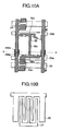
- FIG. 10A is a plan view of a region in which a first metal layer and a second metal layer shown in FIG. 7 are formed;
- FIG. 10B is a plan view of a region in which a transparent electrode (ITO) shown in FIG. 7 is formed and shows a pattern overlapped on an upper portion in FIG. 10A;
- ITO transparent electrode
- FIG. 11 shows cross sections of a TFT substrate side of the unit pixel in the present invention, taken along lines A-A′, B-B′ and C-C′ in FIG. 12;
- FIG. 12 corresponds to FIG. 7 and is a plan view of the portions of the TFT substrate side shown in FIG. 11;
- FIG. 13 is a partial cross section of the unit pixel, showing a relation in width between a data line and a common electrode;
- FIG. 14 is a partial cross section of the unit pixel, showing a relation in width between the data line and a black matrix layer;
- FIG. 15 is a plan view showing a region of an opposing substrate shown in FIG. 7, in which the black matrix layer is formed;
- FIG. 16 is a partial cross section of the liquid crystal display device according to the present invention, for explaining a merit when the common electrode is a transparent electrode (ITO);
- ITO transparent electrode
- FIG. 17 is a plan view illustrating an arrangement of contact holes of the liquid crystal display device according to the present invention.
- FIG. 18A to FIG. 18K are cross sections of the liquid crystal display device according to the present invention, showing manufacturing steps of a manufacturing method thereof;
- FIG. 19 illustrates a correction method for correcting an exposure patterning of an amorphous silicon layer with respect to a first metal layer in photolithography in the present invention
- FIG. 20 illustrates a correction method for correcting an exposure patterning of a second metal layer with respect to the first metal layer in photolithography in the present invention
- FIG. 21A is a plan view showing a region formed by a first metal layer and a second metal layer in a second embodiment of the present invention.
- FIG. 21B is a plan view showing a region formed by a transparent electrode (ITO) to be overlapped on the region shown in FIG. 21A;
- ITO transparent electrode
- FIG. 22A is a plan view showing a region formed by a first metal layer and a second metal layer in a third embodiment of the present invention.
- FIG. 22B is a plan view showing a region formed by a transparent electrode (ITO) to be overlapped on the region shown in FIG. 22A;
- ITO transparent electrode
- FIG. 23A is a plan view showing a region formed by a first metal layer and a second metal layer in a fourth embodiment of the present invention.
- FIG. 23B is a plan view showing a region formed by a transparent electrode (ITO) to be overlapped on the region shown in FIG. 23A;
- ITO transparent electrode
- FIG. 24A is a plan view showing a region formed by a first metal layer and a second metal layer in a fifth embodiment of the present invention.
- FIG. 24B is a plan view showing a region formed by a transparent electrode (ITO) to be overlapped on the region shown in FIG. 24A;
- ITO transparent electrode
- FIG. 25A is a plan view showing a region formed by a first metal layer and a second metal layer in a sixth embodiment of the present invention.
- FIG. 25B is a plan view showing a region formed by a transparent electrode (ITO) to be overlapped on the region shown in FIG. 25A;
- ITO transparent electrode
- FIG. 26A is a plan view showing a region formed by a first metal layer and a second metal layer in a seventh embodiment of the present invention.
- FIG. 26B is a plan view showing a region formed by a transparent electrode (ITO) to be overlapped on the region shown in FIG. 26A;
- ITO transparent electrode
- FIG. 26C is a plan view showing a region formed by a first metal layer and a second metal layer in the region shown in FIG. 26A;
- FIG. 26D is a plan view showing a region formed by the second metal layer in the region shown in FIG. 26A;
- FIG. 27A is a plan view showing a region formed by a first metal layer and a second metal layer in an eighth embodiment of the present invention.
- FIG. 27B is a plan view showing a region formed by a transparent electrode (ITO) to be overlapped on the region shown in FIG. 27A;
- ITO transparent electrode
- FIG. 28A is a plan view showing a region formed by a first metal layer and a second metal layer in a ninth embodiment of the present invention.
- FIG. 28B is a plan view showing a region formed by a transparent electrode (ITO) to be overlapped on the region shown in FIG. 28A;
- ITO transparent electrode
- FIG. 29A is a plan view showing a region formed by a first metal layer and a second metal layer in a tenth embodiment of the present invention.
- FIG. 29B is a plan view showing a region formed by a transparent electrode (ITO) to be overlapped on the region shown in FIG. 29A;
- ITO transparent electrode
- FIG. 29C is a plan view showing a region formed by the first metal layer and an amorphous silicon layer in the region shown in FIG. 29A;
- FIG. 29D is a plan view showing a region formed by the second metal layer and an amorphous silicon layer in the region shown in FIG. 29A;
- FIG. 30A is a plan view showing a region formed by a first metal layer and a second metal layer in an eleventh embodiment of the present invention.
- FIG. 30B is a plan view showing a region formed by a transparent electrode (ITO) to be overlapped on the region shown in FIG. 30A;
- ITO transparent electrode
- FIG. 31A is a plan view showing a region formed by a first metal layer and a second metal layer in a twelfth embodiment of the present invention.
- FIG. 31B is a plan view showing a region formed by a transparent electrode (ITO) to be overlapped on the region shown in FIG. 31A;
- ITO transparent electrode
- FIG. 32A is a plan view showing a region formed by a first metal layer and a second metal layer in a thirteenth embodiment of the present invention.
- FIG. 32B is a plan view showing a region formed by a transparent electrode (ITO) to be overlapped on the region shown in FIG. 32A;
- ITO transparent electrode
- FIG. 33A is a plan view showing a region formed by a first metal layer and a second metal layer in a fourteenth embodiment of the present invention.
- FIG. 33B is a plan view showing a region formed by a transparent electrode (ITO) to be overlapped on the region shown in FIG. 33 A.
- ITO transparent electrode
- an IPS mode AMLCD 10 is constructed with an active element substrate 11 , an opposing substrate 12 and a liquid crystal layer 13 held between the active element substrate 11 and the opposing substrate 12 .
- the opposing substrate 12 is composed of a transparent insulating substrate 16 , a black matrix layer 17 formed on a surface of the transparent insulating substrate 16 as a light shielding film, a color layer 18 overlapped partially on the black matrix layer 17 and a transparent overcoat film 19 formed on the black matrix layer 17 and the color layer 18 . Further, in order to prevent electric charges produced by such as touching from a surface of the liquid crystal display panel from electrically influencing the liquid crystal layer 13 , a transparent, electrically conductive layer 15 is formed on a surface of the transparent insulating substrate 16 .
- the color layer 18 is formed of a resin film containing red (R), green (G) and blue (B) color dyes or pigments.
- the active element substrate 11 is composed of a transparent insulating substrate 22 , a first metal layer forming a scanning line 28 and a gate electrode 30 c formed on the transparent insulating substrate 22 , a first interlayer insulating film 23 formed on the first metal layer, a land shaped amorphous silicon film formed on the first interlayer insulating film 23 , a second metal layer forming a data line 24 and a source electrode 30 b and a drain electrode 30 a of a TFT 50 , a first film 25 a of the second interlayer insulating film formed thereon, a second film 25 b of the second interlayer insulating film formed on the first film 25 a and a common electrode 26 and a pixel electrode 27 , which are formed of a transparent electrode material on the second film 25 b.
- a pixel auxiliary electrode 35 to be described later is formed on the first interlayer insulating film 23 together with the data line 24 .
- the data line 24 and the pixel auxiliary electrode 35 are formed by the second metal layer.
- layers on the active element substrate 11 as well as the opposing substrate 12 which are closer to the liquid crystal layer 13 , will be referred to as upper layers and layers, which are remoter from the liquid crystal layer 13 , will be referred to as lower layers.
- An alignment layer 31 and an alignment layer 20 are formed on a surface of the active element substrate 11 and a surface of the opposing substrate 12 , respectively.
- the liquid crystal layer 13 is rubbed such that liquid crystal molecules are homogeneously oriented in a predetermined direction tilted by about 10 to 30 degrees with respect to the extending direction of the pixel electrode 27 and the common electrode 26 as shown in FIG. 7 and the alignment layers 31 and 20 of the active element substrate 11 and the opposing substrate 12 are bonded to surfaces of the liquid crystal layer 13 .
- the above mentioned tilting angle is referred to as initial orientation direction of liquid crystal molecule.
- a spacer (not shown) for maintaining a thickness of the liquid crystal layer 13 is arranged between the active element substrate 11 and the opposing substrate 12 and a seal (not shown) for preventing liquid crystal molecules from leaking out is formed around the liquid crystal layer 13 .
- width of the black matrix layer 17 is smaller than that of the common electrode 26 formed of a transparent electrode material and completely covering the data line 24 so that light transmitting through the common electrode is not blocked.
- the data line 24 for supplying data signal, the common electrode wiring portions 26 a and 26 b and the common electrode 26 to which the reference potential is applied, the pixel electrode corresponding to a pixel to be displayed, the scanning line 28 to which a scan signal is supplied and the TFT 50 , etc., are provided on the active element substrate 11 .
- the TFT 50 includes the gate electrode 30 c , the drain electrode 30 a and the source electrode 30 b and is provided in the vicinity of a cross point of the scanning line 28 and the data line 24 correspondingly to each pixel.
- the gate electrode 30 c , the drain electrode 30 a and the source electrode 30 b are electrically connected to the scanning line 28 , the data line 24 and the pixel electrode 27 , respectively.
- the common electrode 26 and the pixel electrode 27 have comb configurations, respectively, and the comb teeth of the respective electrodes extend in parallel to the data line 24 . Further, the comb teeth of the common electrode 26 and the comb teeth of the pixel electrode 27 are interleaved mutually.
- the common electrode 26 formed of the transparent electrode material is connected to the common electrode wiring portion 26 b through a common electrode contact hole 39 a.
- FIG. 10 A and FIG. 10B are plan views showing the common electrode 26 and the pixel electrode 27 shown in FIG. 7 separately to distinguish one formed of the transparent electrode material from the other.
- FIG. 11 shows the TFT element portion, the unit pixel portion and the common electrode contact hole portion of the unit pixel portion of the liquid crystal display device 10 according to this embodiment together.
- the respective portions are shown as cross sections basically taken along lines A-A′, B-B′ and C-C′ in the FIG. 7 .
- FIG. 11 shows a case where the second interlayer insulating film 25 is a lamination of the first film 25 a and the second film 25 b .
- the second interlayer insulating film 25 has a single layer structure, it may be considered that the first film is a lower layer of the second interlayer insulating film and the second film of the second interlayer insulating film is an upper layer of the second interlayer insulating film.
- the common electrode wiring portions 26 b and 26 a are formed by the first metal layer and extend in parallel to the scanning line and a peripheral portion of the common electrode wiring is connected to a common electrode potential, as shown in FIG. 11 and FIG. 7 .
- Protrusions 299 a and 299 b are formed in at least one of the common electrode wiring portions 26 a and 26 b such that the data line 24 to be formed in a later step is put therebetween along the extending direction of the data line.
- the pixel electrode 27 formed of the transparent electrode material is formed by a second metal layer and connected to the pixel auxiliary electrode 35 integrally formed with the source 30 b of the TFT 50 through the pixel electrode contact hole 39 b , as shown in FIG. 7 .
- a predetermined display is performed by generating electric field parallel to the transparent insulating substrates 16 and 22 between the common electrode 26 and the pixel electrode 27 of a pixel, which is selected by the scan signal supplied through the scanning line and written in with a data signal supplied through the data line 24 , and rotating orientation direction of liquid crystal molecule in a plane parallel to the transparent insulating substrates 16 and 22 according to the electric field.
- FIG. 10B narrow vertical regions surrounded by the comb teeth of the common electrode 26 and the comb teeth of the pixel electrode 27 are referred to as “columns”.
- the common electrode 26 and the pixel electrode 27 are formed of ITO (Indium Tin Oxide), which is a transparent electrically conductive material.
- the pixel auxiliary electrode 35 integrally formed with the source electrode 30 b of the TFT 50 which is formed by the second metal layer on the first interlayer insulating film 23 , may be provided below the second interlayer insulating film 25 as shown in FIG. 10 A and FIG. 11 .
- the pixel auxiliary electrode 35 includes a first portion 35 a on the common electrode wiring portion 26 b formed by the first metal layer to form a storage capacitor, a second portion 35 b on the common electrode wiring portion 26 a formed by the first metal layer to form a storage capacitor and a third portion 35 c , which extends in parallel to the data line 24 , is positioned below the pixel electrode 27 formed on the second interlayer insulating film 25 by a transparent metal and connects the first portion 35 a and the second portion 35 b together and the first, second and third portions constitute a letter “I” shape.
- the first, second and third portions 35 a , 35 b and 35 c of the pixel auxiliary electrode 35 are formed on the first interlayer insulating film 23 by the second metal layer, which is formed of an opaque metal.
- the drain electrode 30 a and the source electrode 30 c of the TFT 50 are formed by the second metal layer and the source electrode 30 b of the TFT is connected to the pixel auxiliary electrode 35 .
- transmittivity may be lowered to some extent.
- the configuration of the pixel auxiliary electrode 35 is not limited to that shown in FIG. 10 and may be any, provided that it is positioned below the pixel electrode 27 .
- the gate electrode 30 c of the TFT 50 is formed by the first metal layer. Since it is possible, by connecting the common electrodes 26 mutually, to form the storage capacitances on both sides of the pixels, the storage capacitance can be made large and the display can be stabilized.
- the common electrode 26 is formed in the layer higher than the data line 24 and completely covers the data line 24 except the region thereof in which the data line 24 and the scanning line 28 cross each other and the region in the vicinity of the cross region. That is, as shown in FIG. 13, L(COM)>L(D) is established, where L(COM) is width of the common electrode 26 and L(D) is width of the data line 24 , and the width L(D) is within the width L(COM).
- the common electrode 26 since the region in which the data line 24 and the scanning line 28 cross each other and the region in the vicinity of the cross region include large step portions, the common electrode 26 does not cover the data line 24 in these regions in order to prevent short-circuit.
- the width of the black matrix layer 17 on the data line 24 is set smaller than the width of the common electrode 26 and there is no light shielding film between the common electrode 26 and the pixel electrode 27 adjacent to the common electrode 26 in plan view. Further, the black matrix layer 17 is narrower than the data line 24 and overlaps with the data line 24 in the whole region thereof. That is, as shown in FIG. 14, L(D)>L(BM) is established, where L(BM) is the width of the black matrix layer 17 , and L(BM) is included within L(D).
- the width of the black matrix layer 17 is smaller than the width of the data line 24 , light transmitted through bulging portions of the transparent common electrode 26 covering the data line 24 can be utilized completely, so that the transmittivity of the panel can be further improved.
- the black matrix layer 17 is 6 ⁇ m wide.
- the width of the black matrix layer 17 is not limited thereto and, preferably, larger than 6 ⁇ m.
- reflection from the data line 24 becomes large and, therefore, an image displayed on the display panel may become unclear in a bright environment.
- the common electrode 26 may be formed of a material, which is the same as a material coating terminals of the present liquid crystal display device 10 . That is, it is possible to form the terminals in the same ITO layer of the common electrode 26 like the contact hole 39 a shown in FIG. 11 .
- the common electrode 26 can be formed in the same manufacturing step and of the same material as those of the terminals portion of the present liquid crystal display device 10 and, hence, it is possible to prevent an increase of the number of steps due to formation of the common electrode 26 .
- the common electrode 26 when the common electrode 26 does not cover the data line 24 completely in the plan view, the common electrode 26 can not shield electric field from the data line 24 . Therefore, electric field is generated between the data line 24 and the adjacent pixel electrode 27 , causing an erroneous operation of liquid crystal in that area. That is, liquid crystal in that area performs an operation, which is not defined by a potential difference between the common electrode 26 and the pixel electrode 27 , causing vertical cross-talk.
- the black matrix layer 17 in the opposing substrate 12 When there is the black matrix layer 17 in the opposing substrate 12 and the width of the black matrix layer 17 is sufficiently large to cover the data line 24 , it may be enough to shield the erroneous operation region against a viewer.
- the black matrix layer 17 of the opposing substrate 12 does not cover the data line 24 , it is possible to shield the erroneous operation region against a viewer by providing a light shielding layer connected to the common electrode 26 below the data line 24 to shield light from a back light. If this light shielding layer is not connected to the common electrode 26 , the potential thereof becomes unstable and, as a result, DC electric field may be generated between the pixel electrode 27 and the common electrode 26 or an erroneous operation such as cross-talk may occur.
- a light shielding layer connected to the common electrode wiring portion 26 a through the first metal layer forming the scanning line 28 is formed. Since the common electrode wiring portions 26 a and 26 b are connected to the common electrode 26 through the contact-hole 39 a , the common electrode wiring portions 26 a and 26 b may be used as a light shielding layer.
- the light shielding layer may be constructed as a single layer of, for example, chromium, titanium, molybdenum, tungsten or aluminum or a lamination of layers of these metals. When the laminated light shielding layer structure is used, it is possible to reduce an electric resistance thereof.
- the common electrode 26 does not cover the data line 24 in the region in which the data line 24 and the scanning line 28 cross each other and the region in the vicinity thereof. Therefore, the common electrode 26 can not shield electric field of the data line 24 in the region in which it crosses the scanning line 28 . Consequently, electric field is generated between the data line 24 and the adjacent pixel electrode 27 , causing erroneous operation of liquid crystal. Further, liquid crystal may erroneously operate by electric field of the scanning line 28 .
- the common electrode wiring portions 26 a and 26 b are formed in the first metal layer forming the scanning line 28 , it is impossible to shield the erroneously operable regions by the common electrode wiring portions 26 a and 26 b . in view of this, it is preferable to shield these erroneously operable regions by the black matrix layer 17 provided on the side of the opposing substrate.
- FIG. 15 shows an example of the above mentioned structure.
- a region between the scanning line 28 and the pixel electrode 27 and a region in the vicinity thereof, which are defined by thick solid lines, are shielded.
- the common electrode 26 in the present AMLCD 10 is formed of ITO, which is a transparent, electrically conductive material. Therefore, the area of the transparent region in the present liquid crystal display device 10 is increased, so that it is possible to improve the aperture ratio.
- sheet resistance of the ITO film is as large as about 100 ⁇ / ⁇ , it is possible to reduce the resistance of a whole wiring of the common electrodes and provide redundancy thereof by laterally connecting the common electrodes 26 formed by the ITO layer.
- the second interlayer insulating film 25 is provided between the common electrode 26 and the data line 24 . It is possible to reduce parasitic capacitance between the data line 24 and the common electrode 26 by selecting d/ ⁇ sufficiently large, where d is thickness of the second interlayer insulating film 25 and ⁇ is dielectric constant thereof.
- the longitudinal cross-talk is restricted, it is unnecessary to form a black matrix layer for preventing defective display caused by electric field leakage from the data line 24 . Therefore, since it is enough to form the black matrix layer 17 for only improving contrast, it is possible to reduce the width of the black matrix layer 17 . With the reduction of the width of the black matrix layer 17 , it is possible to make the aperture ratio of the present liquid crystal display device 10 larger.
- the common electrode 26 and the pixel electrode 27 are formed on the second interlayer insulating film 25 .
- the common electrode 26 and the pixel electrode 27 are formed in the same layer, it is possible to form the common electrode 26 and the pixel electrode 27 of the same material in the same step and, therefore, it is possible to improve the manufacturing efficiency.
- the common electrode 26 shielding the data line 24 is formed of ITO. Therefore, it is possible to improve the reliability of the present liquid crystal display device 10 , compared with a case where the common electrode 26 is formed of another metal. The reason for this will be described.
- the common electrode 26 and the pixel electrode 27 are formed of other metal than ITO on the second interlayer insulating film 25 and an alignment layer 31 covering the common electrode 26 and the pixel electrode 27 and having thickness of 50 to 100 nm is formed on the second interlayer insulating film 25 .
- liquid crystal material forming the liquid crystal layer 13 and the metal forming the common electrode 26 and the pixel electrode 27 are electrochemically reacted through the pin hole 51 to ionize the metal forming the common electrode and the pixel electrode and ions 52 thus produced may be eluted into the liquid crystal layer 13 .
- Such elution of the metal ions 52 into the liquid crystal layer 13 becomes a cause of the display variation of the liquid crystal display device.
- the liquid crystal layer 13 is formed of a liquid crystal material having strong polarity
- the elution of the metal ions 52 into the liquid crystal layer 13 becomes substantial. Since, in the IPS mode liquid crystal display device, it is necessary to use a liquid crystal material having large dielectric constant anisotropy ⁇ , the elution of the metal ions 52 is particularly severe.
- the common electrode 26 and the pixel electrode 27 provided in contact with the alignment layer 31 should be formed of a material, which is stable with respect to the electrochemical reaction with the liquid crystal material, that is, a material having reactivity with the liquid crystal material is low.
- ITO is a very stable material in such electrochemical reaction as proved by the fact that it has been used as a transparent electrode material in the TN (Twisted Nematic) and the STN (Super Twisted Nematic) type liquid crystal display devices. Therefore, the common electrode 26 and the pixel electrode 27 formed of ITO can be used in directly contact with the alignment layer 31 and can improve the reliability of the present liquid crystal display device 10 , compared with the case where the common electrode 26 and the pixel electrode 27 are formed of other metal than ITO.
- the common electrode 26 is formed to completely cover the data line 24 in almost all regions. It is preferable that the common electrode 26 has aprons each 1.5 ⁇ m wide or more on both sides of the data line 24 .
- the second interlayer insulating film 25 of the present liquid crystal display device 10 is 1 to 2 ⁇ m thick. Further, the second interlayer insulating film 25 may be formed by a single layer film of inorganic or organic material.
- the second interlayer insulating film 25 may take a lamination structure including a first film of inorganic material and a second film of organic material covering the first film, as shown in FIG. 11 .
- dielectric constant of the organic film is lower than that of the inorganic film, it is possible to reduce dielectric constant of the whole interlayer insulating film having the lamination structure, compared with the case where the interlayer insulating film has the single layer structure.
- an interface between the semiconductor layer of the TFT and the organic film covering the semiconductor layer becomes unstable and, when it is driven at high temperature, leak current of the TFT is increased, causing display variation.
- an inorganic film such as a silicon nitride film as the first film in contact with the semiconductor layer of the TFT and laminating an organic film on the inorganic film, a stable interface between the inorganic film and the semiconductor layer is formed, so that a problem such as mentioned above can be restricted.
- the inorganic film may be selected from a group consisting of a SiNx (silicon nitride) film, an inorganic polysilazane film, a lamination film of a silicon nitride film and a silicon oxide film and a lamination film of a silicon nitride film and an inorganic polysilazane film.
- the organic film may be selected from a group consisting of a BCB (benzocyclobutene) film, an organic polysilazane film and a siloxane film.
- BCB benzocyclobutene
- the first film may be a silicon nitride film and the second film may be a photosensitive acrylic resin film or a photosensitive polyimide resin film.
- thickness of the inorganic film in the case where the second interlayer insulating film 25 is the lamination is 0.15 ⁇ m.
- the film thickness is not limited thereto.
- a preferable thickness range of the inorganic film is from about 0.1 ⁇ m to about 1.0 ⁇ m.
- the common electrode 26 is formed of a transparent material, the transparent area of the panel is increased by an area of the region occupied by the common electrode 26 and it is possible to improve the aperture ratio of the present liquid crystal display device 10 .
- the common electrode wiring portion 26 a on the lower side of the unit element and to form the common electrode wiring portion 26 b on the upper side of the unit element.
- the common electrode wiring portions 26 a and 26 b on the lower and upper sides of the unit element, respectively, it is possible to increase the storage capacitance, compared with the case where the common electrode wiring is formed on either of the upper and lower sides of the unit element.
- the TFT 50 When the TFT 50 is arranged on the lower side of the unit pixel as in the case of the present liquid crystal display device 10 , it is possible to connect the pixel electrode 27 to the drain layer forming the drain electrode 30 a on the lower side of the unit element through the contact hole 39 b and to connect the common electrode 26 to the common electrode wiring portion 26 b on the upper side of the unit element through the contact hole 39 a , as shown in FIG. 17 .
- the second interlayer insulating film 25 takes in the form of a lamination of an inorganic film and an organic film and the TFT element portion, the unit pixel portion and the contact hole portion of the common electrode, which have the structures shown by the cross sections taken along the lines A-A′, B-B′ and C-C′ in FIG. 12, are shown as being formed in one region.
- the protruded portions 299 a and 299 b of the common electrode wiring are formed in the same layer as that of the scanning line, which is formed initially by photolithography, such that the protruded portions extend along the extending direction of at least one of the common electrode wiring portions 26 a and 26 b on both sides of the data line 24 , which is formed in a later step.
- liquid crystal display device which is highly reliable, has a high aperture ratio and a large viewing angle, according the present invention.
- the second interlayer insulating film 25 is a lamination of the inorganic film and an organic film.
- the gate electrode 30 c and the common electrode wiring portions 26 a and 26 b are formed by patterning the first metal layer formed of chromium on the transparent insulating substrate 22 of glass by photolithography and dry etching.
- the common electrode wiring portion 26 b is shown in FIG. 18A to FIG. 18K, the common electrode wiring portion 26 a , which is inevitable, will be described together in the following description.
- the photolithography is performed by depositing a film to be patterned on a whole surface of the transparent insulating substrate 22 , forming a photosensitive resin film on the whole surface of the deposited film by spin coating, exposing the photosensitive resin film with light having a specific wavelength with which the photosensitive organic film is hardened by using a photo mask shielding only a desired pattern and processing the organic film resist with a specific developer such that portions of the photosensitive organic film resist, which are not hardened, are removed.
- the film to be patterned is patterned by using the remaining portion of the hardened photosensitive organic film resist as a protective film for the film to be patterned and the desired pattern is formed by removing the resist by dipping it in a peeling liquid.
- the protruded portions 299 a and 299 b of the common electrode wiring each being 2 ⁇ m wide or more in the extending direction parallel to the longitudinal direction of the data line and having a length in a range from 5 ⁇ m to the length of the aperture are formed in at least one of the common electrode wiring portions 26 a and 26 b such that the protruded portions extend along the extending direction of at least one of the common electrode wiring portions 26 a and 26 b on both sides of the data line 24 , which is formed in a later step.
- each of the protruded portions 299 a and 299 b of the common electrode wiring will be described as being 2 ⁇ m wide and 20 ⁇ m long.
- the first interlayer insulating film 23 in the form of a lamination of a silicon dioxide (SiO 2 ) film and a silicon nitride (SiNx) film is formed on the whole surface of the transparent insulating substrate 22 to cover the gate electrode 30 c , the common electrode wiring portions 26 a and 26 b and the protruded portions 299 a and 299 b thereof.
- an amorphous silicon film composed of a a-Si film 32 and an n+a-Si film 33 is formed on the whole surface of the first interlayer insulating film 23 .
- the amorphous silicon film ( 32 and 33 ) is patterned by photolithography and dry etching to form a land-shaped semiconductor layer of the TFT.
- the exposure of the amorphous silicon film ( 32 and 33 ) in the photolithography processing is performed by using a matching marker formed by the underlying first metal layer, which is the gate electrode 30 c and the common electrode wiring portions 26 a and 26 b , as a reference.
- the gate electrode 30 c and the common electrode wiring portions 26 a and 26 b which extend in the lateral direction, and the protruded portions 299 a and 299 b of the common electrode wiring, which extend in the vertical direction, exist in the underlying first metal layer, it is possible to measure a lateral and vertical deviations of the organic film resist pattern, which is left through the exposure step and the developing step of the amorphous silicon film ( 32 and 33 ), every exposure shot by measuring the vertical and lateral parallel lines by the fine distance measuring device with using the protruded portions as the markers, as shown in FIG. 19 .
- outside edges of the paired protruded portions 299 a and 299 b formed in the common electrode wiring portion 26 b are finely measured to determine a center value W 1 between the protruded portions.
- edges of the organic film resist in the lateral direction with respect to the amorphous silicon film 29 is measured finely to determine a center value W 2 of the amorphous silicon film 29 in the lateral direction.
- a correction of the deviations is performed for the exposure in the lateral direction on the basis of photo mask data containing these center values W 1 and W 2 .
- edges of the scanning line 28 are measured finely to determine a center value W 3 of the scanning line.
- edges of the organic film resist with respect to the amorphous silicon film 29 in the vertical direction are measured finely to determine a center value W 4 of the amorphous silicon film 29 in the vertical direction.
- a correction of the deviations is performed for the exposure in the vertical direction on the basis of photo mask data containing these center values W 3 and W 4 .
- the length of the protruded portion In order to restrict a reading error when a distance is measured accurately by the fine distance measuring device, a pattern having a width of 2 ⁇ m or more is necessary. Further, the length of the protruded portion must be 5 ⁇ m or more. The width of the protruded portion, which is 2 ⁇ m or more, is enough. However, when the width is too large, the area of the aperture may be shielded by the common electrode wiring, which is formed of opaque material. Therefore, the width of the protruded portion is preferably 10 ⁇ m or smaller. The length of the protruded portion, which is 5 ⁇ m or more, is enough.
- the length of the protruded portion is not larger than the length of the aperture, preferably 20 ⁇ 40 ⁇ m.
- the width and the length of the common electrode wiring ( 299 a , 299 b ) are 2 ⁇ m and 20 ⁇ m, respectively, the reading error is not large.
- the resist which is hardened, can be removed by dipping it in a peeling liquid. After the resist is removed, a precise pattern formation with respect to the underlying first metal layer can be done by forming a photosensitive organic film resist by spin coating again and correcting the exposure data on the basis of an information obtained by the fine distance measuring device.
- a chromium layer is deposited on the whole surface as the second metal layer and is patterned by photolithography and dry etching to form the drain 30 c and the source electrode 30 b of the TFT 50 , the data line 24 and the pixel auxiliary electrode 35 , as shown in FIG. 18 E.
- the exposure of the drain electrode 30 a and the source electrode 30 b of the TFT 50 , the data line 24 and the pixel auxiliary electrode 35 , which are formed by the second metal layer, in photolithography is performed by using a matching marker formed by the underlying first metal layer, which is the gate electrode 30 c and the common electrode wiring portions 26 a and 26 b , as a reference, similarly to that shown in FIG. 18 D.
- edges of the organic film resist in the lateral direction with respect to the drain electrode 30 a and the source electrode 30 b formed by the second metal layer is measured finely to determine a center value W 2 of the drain electrode 30 a and the source electrode 30 b in the lateral direction.
- a correction of the deviations is performed for the exposure in the lateral direction on the basis of photo mask data containing these center values W 1 and W 2 .
- edges of the scanning line 28 are measured finely to determine a center value W 3 of the scanning line.
- a distance between the drain electrode 30 a and the source electrode 30 b is measured finely to determine a center value W 4 thereof.
- a correction of the deviations is performed for the exposure in the vertical direction on the basis of photo mask data containing these center values W 3 and W 4 .
- a channel of the TFT 50 is formed in the aperture between the drain electrode 30 a and the source electrode 30 b thereof by etching the n+type a-Si film 33 and the a-Si film 32 up to a middle level of the amorphous silicon film with using the drain electrode 30 a and the source electrode 30 b as a mask.
- an inorganic first film 25 a of the second interlayer insulating film 25 which is formed of silicon nitride, is deposited on the whole surface.
- an organic second film 25 b of the second interlayer insulating film 25 which is formed of photosensitive acrylic resin, is deposited on the first film 25 a.
- the photosensitive acrylic resin film 25 b is exposed, developed and sintered and a contact hole 39 b for the pixel electrode, which reaches the silicon nitride film of the first interlayer insulating film 23 , and a contact hole 39 a for the common electrode, which reaches the silicon nitride of the interlayer insulating film 23 , are formed on the source electrode 30 b and the common electrode wiring portion 26 b , respectively.
- the exposure of the photosensitive acrylic resin film as the second film 25 b of the second interlayer insulating film 25 in the photolithographic processing is performed by using the matching marker of the first metal layer or the matching marker of the second metal layer as a reference.
- the marker as the reference of the first metal layer or the second metal layer is determined by selecting one of the contact holes 39 a and 39 b whose margin is smaller.
- the exposed first nitride film as the first film 25 a of the second interlayer insulating film 25 is etched away through the contact hole 39 b for the pixel electrode and the contact hole 39 a for the common electrode.
- the contact hole 39 b reaches the pixel electrode.
- the etching through the contact hole 39 a is further performed up to the common electrode wiring portion 26 a or 26 b by etching away the first interlayer insulating film 23 composed of the silicon dioxide (SiO 2 ) film and the silicon nitride (SiNx) film.
- the exposure of the silicon nitride film as the first film 25 a of the second interlayer insulating film 25 in the photolithographic processing is performed by using the matching marker of the first metal layer or the matching marker of the second metal layer as a reference.
- the marker as the reference of the first metal layer or the second metal layer is determined by selecting one of the contact holes 39 a and 39 b whose margin is smaller.
- an ITO film 46 is deposited on the whole surface to cover inner walls of the contact holes 39 a and 39 b and, as shown in FIG. 18K, the common electrode 26 and the pixel electrode 27 are formed from the ITO film 46 in the unit element forming region by photolithography and etching.
- the exposure to the ITO film 46 by photolithography is performed by using the matching marker of the second metal layer as a reference. This is because, when the common electrode 26 , which is formed of ITO and covers the data line, is deviated with respect to the data line 24 , the vertical cross-talk may occur.
- the exposure error of the amorphous silicon layer and the second metal layer, which are formed after the formation of the protruded portions, can be corrected by the protruded portions, it is possible to manufacture the liquid crystal display device having improved aperture ratio and having no unevenness of display such as unevenness of division, without increase of the manufacturing cost.
- FIG. 21 A and FIG. 21B shows the second embodiment, which are basically the same as FIG. 10 A and FIG. 10B showing the first embodiment shown in FIG. 7, which show the region formed by the first and second metal layers shown in FIG. 7 and the region formed of ITO shown in FIG. 7, respectively.
- a manufacturing method of the liquid crystal display device according to the second embodiment is also the same as that of the first embodiment.
- the second embodiment differs from the first embodiment in the configuration of the protruded portions formed in the common electrode wiring portion 26 a and extending in parallel to the longitudinal direction of the data line.
- the protruded portions 299 a and 299 b of the common electrode wiring 26 are arranged on both sides of the data line 24 in a plane in the first embodiment, only one protruded portion ( 299 a ) having width larger than width of the protruded portion in the first embodiment is provided adjacent to the data line as shown in FIG. 21 .
- the protruded portion 299 a is 5 ⁇ m wide and 5 ⁇ m long.
- FIG. 22 A and FIG. 22B shows the second embodiment, which are basically the same as FIG. 10 A and FIG. 10B showing the first embodiment shown in FIG. 7, which show the region formed by the first and second metal layers shown in FIG. 7 and the region formed of ITO shown in FIG. 7, respectively.
- a manufacturing method of the liquid crystal display device according to the second embodiment is also the same as that of the first embodiment.
- the second embodiment differs from the first embodiment in the configuration of the protruded portions formed in the common electrode wiring portion 26 a and extending in parallel to the longitudinal direction of the data line.
- protruded portions 299 a and 299 b of the common electrode wiring 26 are arranged adjacently on both sides of the data line 24 in a plane in the first embodiment, a protruded portion 299 a is provided adjacently on one side of the data line 24 and another protruded portion 299 c is provided slightly remote from the protruded portion 299 a as shown in FIG. 22 A.
- the liquid crystal display device Since it is possible to correct the exposure error in exposing the amorphous silicon layer and the second metal layer, which are formed after the formation of the common electrode wiring, in such arrangement of the protruded portions, it is possible to manufacture the liquid crystal display device having improved aperture ratio and having no unevenness of display such as unevenness of division, without increase of the manufacturing cost.
- FIG. 23 A and FIG. 23B shows the fourth embodiment, which are basically the same as FIG. 21 A and FIG. 21B showing the second embodiment, which show the region formed by the first and second metal layers and the region formed of ITO, respectively.
- a manufacturing method of the liquid crystal display device according to the second embodiment is also the same as that of the first embodiment.
- the fourth embodiment differs from the second embodiment in the configuration of the protruded portions formed in the common electrode wiring portion 26 a and extending in parallel to the longitudinal direction of the data line.
- a protruded portion 299 a of the common electrode wiring portion 26 a is arranged in every pixel in the second embodiment, a protruded portion 299 a is provided in only R pixel among the pixels of red (R), green (G) and blue (B) in the fourth embodiment as shown in FIG. 23 A.
- the liquid crystal display device Since it is possible to correct the exposure error in exposing the amorphous silicon layer and the second metal layer, which are formed after the formation of the common electrode wiring, in even such arrangement of the protruded portions, it is possible to manufacture the liquid crystal display device having improved aperture ratio and having no unevenness of display such as unevenness of division, without increase of the manufacturing cost.
- the protruded portion 299 a may be provided in only pixel for color B or only pixel for color G.
- one protruded portion 299 a may be provided at intervals of two or more units.
- the liquid crystal display device Since it is possible to correct the exposure error in exposing the amorphous silicon layer and the second metal layer, which are formed after the formation of the common electrode wiring, in such arrangement of the protruded portions, it is possible to manufacture the liquid crystal display device having improved aperture ratio and having no unevenness of display such as unevenness of division, without increase of the manufacturing cost.
- FIG. 24 A and FIG. 24B shows the fifth embodiment, which are basically the same as FIG. 10 A and FIG. 10B showing the first embodiment, which show the region formed by the first and second metal layers and the region formed of ITO, respectively.
- a manufacturing method of the liquid crystal display device according to the second embodiment is also the same as that of the first embodiment.
- the fifth embodiment differs from the first embodiment in the configuration of the protruded portions formed in the common electrode wiring portion 26 a and extending in parallel to the longitudinal direction of the data line.
- the protruded portions 299 a and 299 b of the common electrode wiring 26 are adjacently arranged on both sides of the data line 24 in the first embodiment, the protruded portions 299 a and 299 b are provided on both sides of the pixel auxiliary electrode 35 in the fifth embodiment as shown in FIG. 24 A and FIG. 24 B.
- the liquid crystal display device Since it is possible to correct the exposure error in exposing the amorphous silicon layer and the second metal layer, which are formed after the formation of the common electrode wiring, in even such arrangement of the protruded portions, it is possible to manufacture the liquid crystal display device having improved aperture ratio and having no unevenness of display such as unevenness of division, without increase of the manufacturing cost.
- FIG. 25 A and FIG. 25B shows the sixth embodiment, which are basically the same as FIG. 10 A and FIG. 10B showing the first embodiment, which show the region formed by the first and second metal layers and the region formed of ITO, respectively.
- a manufacturing method of the liquid crystal display device according to the second embodiment is also the same as that of the first embodiment.
- the sixth embodiment differs from the first embodiment in which the protruded portions extending in parallel to the longitudinal direction of the data line in that floating films 300 a and 300 b , which extend in parallel to the longitudinal direction of the data and are formed by the first metal layer, are arranged on both sides of the data line 24 in an electrically floating state with respect to any electrode.
- the liquid crystal display device Since it is possible to correct the exposure error in exposing the amorphous silicon layer and the second metal layer, which are formed after the formation of the common electrode wiring, in even such arrangement of the protruded portions, it is possible to manufacture the liquid crystal display device having improved aperture ratio and having no unevenness of display such as unevenness of division, without increase of the manufacturing cost.
- FIG. 26 A and FIG. 26B shows the seventh embodiment, which are basically the same as FIG. 10 A and FIG. 10B showing the first embodiment, which show the region formed by the first and second metal layers and the region formed of ITO, respectively.
- a manufacturing method of the liquid crystal display device according to the second embodiment is also the same as that of the first embodiment.
- the seventh embodiment differs from the first embodiment in which the protruded portions extending in parallel to the longitudinal direction of the data line in that a floating film 300 , which extends in parallel to the longitudinal direction of the data and is formed by the first metal layer, is arranged immediately below the data line 24 in an electrically floating state with respect to any electrode.
- a region shown in FIG. 26A can be shown as a region formed by the first metal layer and the amorphous silicon layer (FIG. 26C) and a region formed by the second metal layer (FIG. 26D)
- the liquid crystal display device Since it is possible to correct the exposure error in exposing the amorphous silicon layer and the second metal layer, which are formed after the formation of the common electrode wiring, in even such arrangement of the protruded portions, it is possible to manufacture the liquid crystal display device having improved aperture ratio and having no unevenness of display such as unevenness of division, without increase of the manufacturing cost.
- FIG. 27 A and FIG. 27B shows the eighth embodiment, which are basically the same as FIG. 10 A and FIG. 10B showing the first embodiment, which show the region formed by the first and second metal layers and the region formed of ITO, respectively.
- a manufacturing method of the liquid crystal display device according to the second embodiment is also the same as that of the first embodiment.
- the eighth embodiment differs from the first embodiment in which the protruded portions 299 a and 299 b are arranged on the both sides of the data line 24 in that a recessed portion 301 is formed in the common electrode wiring portion 26 a in a position adjacent to the data line 24 as shown in FIG. 27 A. Width of the recessed portion 301 is made large similarly to the width of the protruded portion in the second embodiment. In the eighth embodiment, the recessed portion is 5 ⁇ m wide and 5 ⁇ m long.
- the liquid crystal display device Since it is possible to correct the exposure error in exposing the amorphous silicon layer and the second metal layer, which are formed after the formation of the common electrode wiring, in even such arrangement of the recessed portions if the width of the recessed portion is large enough, it is possible to manufacture the liquid crystal display device having improved aperture ratio and having no unevenness of display such as unevenness of division, without increase of the manufacturing cost.
- FIG. 28 A and FIG. 28B shows the ninth embodiment, which are basically the same as FIG. 27 A and FIG. 27B showing the first embodiment, which show the region formed by the first and second metal layers and the region formed of ITO, respectively.
- a manufacturing method of the liquid crystal display device according to the second embodiment is also the same as that of the first embodiment.
- the ninth embodiment differs from the eighth embodiment in that the configuration of a recessed portion formed in the common electrode wiring portion 26 a and extending in parallel to the longitudinal direction of the data line is different from that in the eighth embodiment.
- the recessed portion 301 is formed in the common electrode wiring portion 26 a adjacently to the data line 25 , recessed portions 301 a and 301 b are formed on both sides of the data line 24 in the ninth embodiment as shown in FIG. 28 A. Width of the recessed portion can be made smaller than that in the eighth embodiment and, in this embodiment, the recessed portion is 2 ⁇ m wide and 5 ⁇ m long.
- FIG. 29 A and FIG. 29B shows the seventh embodiment, which are basically the same as FIG. 27 A and FIG. 27B showing the first embodiment, which show the region formed by the first and second metal layers and the region formed of ITO, respectively.
- a manufacturing method of the liquid crystal display device according to the second embodiment is also the same as that of the first embodiment.
- the tenth embodiment differs from the eighth embodiment in which the recessed portion 301 is formed in the common electrode wiring portion 26 a such that it is adjacent to the data line 24 in that a recessed portion 301 c is formed in the common electrode wiring portion 26 a in the vicinity of the contact hole 39 b on both sides of the data line 24 .
- a region shown in FIG. 29A can be shown as a region formed by the first metal layer and the amorphous silicon layer (FIG. 29C) and a region formed by the second metal layer (FIG. 29 D), from which the configuration of the recessed portion 301 c can be understood clearly.
- Width of the recessed portion 301 c is larger than the width of the protruded portion in the eighth embodiment and, in this embodiment, the recessed portion 301 c is 20 ⁇ m wide and 8 ⁇ m long.
- FIG. 30 A and FIG. 30B shows the eleventh embodiment, which are basically the same as FIG. 10 A and FIG. 10B showing the first embodiment shown in FIG. 7, which show the region formed by the first and second metal layers shown in FIG. 7 and the region formed of ITO shown in FIG. 7, respectively.
- a manufacturing method of the liquid crystal display device according to the second embodiment is also the same as that of the first embodiment.
- the eleventh embodiment differs from the first embodiment in the common electrode wiring in which the protruded portions formed in the common electrode wiring portion 26 a and extending in parallel to the longitudinal direction of the data line.
- protruded portions 299 a and 299 b are formed in the common electrode wiring portion 26 a in the first embodiment, protruded portions are formed in the common electrode wiring portion 26 b in the eleventh embodiment as shown in FIG. 30 a .
- Each of the protruded portions 299 d and 299 e is 2 ⁇ m wide and 20 ⁇ m long. Since it is possible to correct the exposure error in exposing the amorphous silicon layer and the second metal layer, which are formed after the formation of the common electrode wiring portion, by measuring a distance between opposite edges of the protruded portion even if the width thereof is small, it is possible to manufacture the liquid crystal display device having improved aperture ratio and having no unevenness of display such as unevenness of division, without increase of the manufacturing cost.
- FIG. 31 A and FIG. 31B shows the twelfth embodiment, which are basically the same as FIG. 28 A and FIG. 28B showing the ninth embodiment, which show the region formed by the first and second metal layers and the region formed of ITO, respectively.
- a manufacturing method of the liquid crystal display device according to the twelfth embodiment is also the same as that of the ninth embodiment.
- the twelfth embodiment differs from the ninth embodiment in that the common electrode wiring in which recessed portions are formed and which extend in parallel to the longitudinal direction of the data line and the number of the protruded portions are different from those in the ninth embodiment.
- the recessed portion 301 is formed in the common electrode wiring portion 26 a adjacently to the data line 25
- recessed portions 301 d and 301 e are formed in the common electrode wiring portion 26 b on both sides of the data line 24 in the twelfth embodiment as shown in FIG. 31 A.
- Each of the recessed portions is 2 ⁇ m wide and 5 ⁇ m long.
- FIG. 32 A and FIG. 32B shows the thirteenth embodiment, which are basically the same as FIG. 10 A and FIG. 10B showing the first embodiment shown in FIG. 7, which show the region formed by the first and second metal layers shown in FIG. 7 and the region formed of ITO shown in FIG. 7, respectively.
- a manufacturing method of the liquid crystal display device according to the second embodiment is also the same as that of the first embodiment.
- a difference of the thirteenth embodiment from the first embodiment is that it has a protruded portion and a recessed portion.
- a protruded portion 28 a is formed in a portion of the scanning line 28 and a recessed portion 301 f is formed in the common electrode wiring portion 26 b in the thirteenth embodiment as shown in FIG. 32 A.
- the protruded portion 28 a is 5 ⁇ m wide and 5 ⁇ m long and the recessed portion 301 f is 5 ⁇ m wide and 5 ⁇ m deep. Since, in this embodiment, the scanning line 28 and the common electrode wiring portions 26 a and 26 b are formed of the same material in the same step, the protruded portion 28 a and the recessed portion 301 f are formed such that a short-circuit between them is prevented.
- FIG. 33 A and FIG. 33B shows the thirteenth embodiment, which are basically the same as FIG. 32 A and FIG. 32B showing the thirteenth embodiment, which show the region formed by the first and second metal layers and the region formed of ITO, respectively.
- a manufacturing method of the liquid crystal display device according to the second embodiment is also the same as that of the first embodiment.
- a difference of the fourteenth embodiment from the thirteenth embodiment is that it has a protruded portion and a recessed portion, which extend in parallel to the longitudinal direction of the data line.
- a recessed portion 28 b is formed in a portion of the scanning line 28 .
- the recessed portion 28 b is 5 ⁇ m wide and 5 ⁇ m deep.
- the structure of the unit element of the liquid crystal display device having the common electrode and the pixel electrode, which are liquid crystal driving electrodes of straight line type has been described in detail.
- the liquid crystal display device which can prevent unevenness of display without increasing the manufacturing cost
- the common electrode and the pixel electrodes have been described as being formed in the same layer, the common electrode and the pixel electrodes may be arranged on both sides of a third interlayer insulating film in view of the provision of the liquid crystal display device, which can prevent unevenness of display without increasing the manufacturing cost.
- the protruded portion or the recessed portion which can be used as a reference in a fine distance measurement during the alignment exposure may be arranged in not all of the pixels but pixels for only R.
- the reference may be provided in pixels for only G or B.
- one protruded portion may be provided at intervals of two or more units.
- the fine distance measurement in the lateral direction is also possible and it is possible to perform a correct alignment. Therefore, it is possible to manufacture a liquid crystal display device having no unevenness of display such as unevenness of division.
- an IPS mode active matrix type liquid crystal display device which has an improved aperture ratio and has no unevenness of display such as unevenness of division, without increasing the manufacturing cost.
Landscapes
- Physics & Mathematics (AREA)
- Nonlinear Science (AREA)
- General Physics & Mathematics (AREA)
- Chemical & Material Sciences (AREA)
- Crystallography & Structural Chemistry (AREA)
- Mathematical Physics (AREA)
- Optics & Photonics (AREA)
- Liquid Crystal (AREA)
- Geometry (AREA)
- Thin Film Transistor (AREA)
- Exposure And Positioning Against Photoresist Photosensitive Materials (AREA)
- Devices For Indicating Variable Information By Combining Individual Elements (AREA)
- Exposure Of Semiconductors, Excluding Electron Or Ion Beam Exposure (AREA)
Abstract
Description
| TABLE 1 | |||||
| Film | Configuration | ||||
| Film | Dielectric | forming | forming | ||
| thickness | constant | method | method | ||
| (1) only | SiNx film | 1˜3 μm | 6.4 | Plasma CVD | Dry etching |
| inorganic | using photo | ||||
| film | resist as | ||||
| mask | |||||
| (1) only | SiNx film/ | 1 μm/ | 6.4/ | Plasma CVD/ | Dry etching |
| inorganic | SiOx film | 0.5 μm | 4.0 | sputtering | using photo |
| film | resist as | ||||
| mask | |||||
| (1) only | Inorganic | 1˜2 μm | 4.5 | Spin | Dry etching |
| inorganic | polysilazane | coating & | using photo | ||
| film | film | sintering | resist as | ||
| mask | |||||
| (1) only | SiNx/ | 0.15 μm/ | 6.4/ | Plasma CVD/ | Dry etching |
| inorganic | inorganic | 1˜2 μm | 4.5 | spin | using photo |
| film | polysilazane | coating & | resist as | ||
| film | sintering | mask | |||
| (2) | SiNx film/ | 0.15 μm/ | 6.4/ | Plasma CVD/ | Sintering |
| inorganic | photosensitive | 1˜2 μm | 3.3 | spin | photosensitive |
| film/organic | acrylic | coating | acrylic resin after | ||
| film | resin film | pattern formation | |||
| lamination | by exposure | ||||
| and | |||||
| development/dry | |||||
| etching of | |||||
| SiNx | |||||
| (2) | SiNx film/ | 0.15 μm/ | 6.4/ | Plasma CVD/ | Sintering |
| inorganic | photosensitive | 1˜2 μm | — | spin | photosensitive |
| film/organic | acrylic | coating | acrylic resin after | ||
| film | resin film | pattern formation | |||
| lamination | by exposure | ||||
| and | |||||
| development/dry | |||||
| etching of | |||||
| SiNx | |||||
| (2) | |||||
| inorganic | |||||
| film/organic | |||||
| film | |||||
| lamination | |||||
| (3) only | BCB (benzo- | 1˜2 μm | 4.5 | Spin | Dry etching |
| organic | cyclobutene) | coating & | using photo | ||
| film | film | sintering | resist as | ||
| mask | |||||
| (3) only | Organic | 1˜2 μm | 3.8 | Spin | Dry etching |
| organic | polysilazane | coating & | using photo | ||
| film | film | sintering | resist as | ||
| mask | |||||
| (3) only | Siloxane | 1˜2 μm | — | Spin | Dry etching |
| organic | film | coating & | using photo | ||
| film | sintering | resist as | |||
| mask | |||||
Claims (14)
Applications Claiming Priority (3)
| Application Number | Priority Date | Filing Date | Title |
|---|---|---|---|
| JP2001-118083 | 2001-04-17 | ||
| JP118083/2001 | 2001-04-17 | ||
| JP2001118083A JP4718712B2 (en) | 2001-04-17 | 2001-04-17 | Active matrix liquid crystal display device |
Publications (2)
| Publication Number | Publication Date |
|---|---|
| US20020191138A1 US20020191138A1 (en) | 2002-12-19 |
| US6744482B2 true US6744482B2 (en) | 2004-06-01 |
Family
ID=18968528
Family Applications (1)
| Application Number | Title | Priority Date | Filing Date |
|---|---|---|---|
| US10/119,362 Expired - Lifetime US6744482B2 (en) | 2001-04-17 | 2002-04-09 | Active matrix type liquid crystal display device having particular positioning reference pattern and fabrication method thereof |
Country Status (4)
| Country | Link |
|---|---|
| US (1) | US6744482B2 (en) |
| JP (1) | JP4718712B2 (en) |
| KR (2) | KR100563699B1 (en) |
| TW (1) | TWI244570B (en) |
Cited By (20)
| Publication number | Priority date | Publication date | Assignee | Title |
|---|---|---|---|---|
| US20030227590A1 (en) * | 2002-06-06 | 2003-12-11 | Ryutaro Oke | Liquid crystal display device |
| US20040041970A1 (en) * | 2002-08-27 | 2004-03-04 | Lg.Philips Lcd Co., Ltd. | In-plane switching mode liquid crystal display device and method of fabricating the same |
| US20040066481A1 (en) * | 2002-10-04 | 2004-04-08 | Lg.Philips Lcd Co., Ltd. | In-plane switching mode liquid crystal display device and fabrication method thereof |
| US20040066483A1 (en) * | 2002-10-04 | 2004-04-08 | Lg.Philips Lcd Co., Ltd. | Array substrate of liquid crystal display device and method of fabricating the same |
| US20040150768A1 (en) * | 2002-11-12 | 2004-08-05 | Chi Mei Optoelectronics Corp. | In-plane switching liquid crystal display device |
| US20040257510A1 (en) * | 2003-06-17 | 2004-12-23 | Lg.Philips Lcd Co., Ltd. | In-plane switching mode liquid crystal display device and method of manufacturing the same |
| US20050117104A1 (en) * | 2001-02-23 | 2005-06-02 | Shinichi Nishida | In-plane switching mode active matrix type liquid crystal display device and method of fabricating the same |
| US20050285617A1 (en) * | 2004-06-25 | 2005-12-29 | Hon Hai Precision Industry Co., Ltd. | System and method for inspecting an LCD panel |
| US20060114400A1 (en) * | 2004-11-26 | 2006-06-01 | Innolux Display Corp. | Liquid crystal display with low consumption storage capacitors |
| US20060227276A1 (en) * | 2005-04-11 | 2006-10-12 | Lg.Philips Lcd Co., Ltd. | In-plane switching mode liquid crystal display device |
| US20060256249A1 (en) * | 2005-05-10 | 2006-11-16 | Mitsubishi Denki Kabushiki Kaisha | Liquid crystal display and manufacturing method therefor |
| US20080106868A1 (en) * | 2006-11-03 | 2008-05-08 | Dell Products L.P. | Thermal interface material volume between thermal conducting members |
| US20090103035A1 (en) * | 2007-10-23 | 2009-04-23 | Nec Lcd Technologies, Ltd. | Lateral electric field type active-matrix addressing liquid crystal display device |
| US20110181824A1 (en) * | 2010-01-28 | 2011-07-28 | Mitsubishi Electric Corporation | Liquid crystal display device |
| US8446552B2 (en) | 2011-03-30 | 2013-05-21 | Au Optronics Corp. | Pixel array of fringe field switching liquid crystal display panel and driving method thereof |
| US20130203196A1 (en) * | 2012-02-07 | 2013-08-08 | Shenzhen China Star Optoelectronics Technology Co., Ltd. | Manufacture method of thin film transistor array substrate |
| US8953132B2 (en) | 2011-03-30 | 2015-02-10 | Au Optronics Corp. | Pixel array of fringe field switching liquid crystal display panel and driving method thereof |
| US20170255071A1 (en) * | 2016-03-04 | 2017-09-07 | Au Optronics Corporation | Array substrate and in-plane switching liquid crystal display panel |
| US20190245162A1 (en) * | 2016-09-28 | 2019-08-08 | Sabic Global Technologies B.V. | Quantum dot film and applications thereof |
| US20210399043A1 (en) * | 2018-09-05 | 2021-12-23 | Samsung Display Co., Ltd. | Display device and method of manufacturing the same |
Families Citing this family (38)
| Publication number | Priority date | Publication date | Assignee | Title |
|---|---|---|---|---|
| JP3957277B2 (en) * | 2002-04-15 | 2007-08-15 | 株式会社アドバンスト・ディスプレイ | Liquid crystal display device and manufacturing method thereof |
| KR100737702B1 (en) * | 2002-10-16 | 2007-07-10 | 엘지.필립스 엘시디 주식회사 | LCD Display |
| KR100760937B1 (en) * | 2002-11-30 | 2007-09-21 | 엘지.필립스 엘시디 주식회사 | Transverse electric field type liquid crystal display device and manufacturing method |
| JP4720970B2 (en) * | 2003-03-19 | 2011-07-13 | 日本電気株式会社 | Liquid crystal display device |
| JP2004325953A (en) | 2003-04-25 | 2004-11-18 | Nec Lcd Technologies Ltd | Liquid crystal display |
| JP2004341465A (en) * | 2003-05-14 | 2004-12-02 | Obayashi Seiko Kk | High quality liquid crystal display device and its manufacturing method |
| KR100741890B1 (en) * | 2003-06-26 | 2007-07-23 | 엘지.필립스 엘시디 주식회사 | Transverse electric field type liquid crystal display device and manufacturing method thereof |
| KR100560400B1 (en) * | 2003-11-04 | 2006-03-14 | 엘지.필립스 엘시디 주식회사 | Horizontal field applied thin film transistor substrate and manufacturing method thereof |
| KR100560405B1 (en) * | 2003-11-04 | 2006-03-14 | 엘지.필립스 엘시디 주식회사 | Horizontal field applied thin film transistor substrate and manufacturing method thereof |
| KR101002333B1 (en) * | 2003-12-02 | 2010-12-17 | 엘지디스플레이 주식회사 | Transverse electric field liquid crystal display device and manufacturing method thereof |
| KR100760940B1 (en) | 2003-12-29 | 2007-09-21 | 엘지.필립스 엘시디 주식회사 | LCD and its manufacturing method |
| JP4174428B2 (en) * | 2004-01-08 | 2008-10-29 | Nec液晶テクノロジー株式会社 | Liquid crystal display |
| JP4506209B2 (en) * | 2004-03-04 | 2010-07-21 | 日本ビクター株式会社 | Method for forming photoresist pattern |
| JP2005257883A (en) * | 2004-03-10 | 2005-09-22 | Nec Lcd Technologies Ltd | Liquid crystal display |
| CN100445807C (en) * | 2004-06-25 | 2008-12-24 | 鸿富锦精密工业(深圳)有限公司 | LCD panel inspection system and method |
| KR100652218B1 (en) | 2004-06-29 | 2006-12-01 | 엘지.필립스 엘시디 주식회사 | Horizontal field type liquid crystal display device and manufacturing method thereof |
| KR101133758B1 (en) * | 2005-01-19 | 2012-04-09 | 삼성전자주식회사 | Sensor and thin film transistor array panel including sensor |
| JP2006203121A (en) * | 2005-01-24 | 2006-08-03 | Seiko Epson Corp | SEMICONDUCTOR DEVICE, ACTIVE MATRIX ELECTRO-OPTICAL DEVICE, ELECTRONIC DEVICE, AND SEMICONDUCTOR DEVICE MANUFACTURING METHOD |
| KR101255299B1 (en) * | 2005-04-28 | 2013-04-23 | 엘지디스플레이 주식회사 | The in-plane switching mode liquid crystal display device |
| KR101253044B1 (en) * | 2005-12-29 | 2013-04-11 | 엘지디스플레이 주식회사 | In plane switching mode liquid crystal display device |
| KR101374107B1 (en) | 2007-10-15 | 2014-03-13 | 엘지디스플레이 주식회사 | Trans-reflective liquid crystal display device and method for fabricating the same |
| KR101291485B1 (en) * | 2009-12-04 | 2013-07-30 | 가부시키가이샤 한도오따이 에네루기 켄큐쇼 | Manufacturing method of semiconductor device |
| US8804081B2 (en) | 2009-12-18 | 2014-08-12 | Samsung Display Co., Ltd. | Liquid crystal display device with electrode having opening over thin film transistor |
| TWI389067B (en) * | 2010-06-29 | 2013-03-11 | Compal Electronics Inc | Display module and assembly method thereof |
| KR101298613B1 (en) | 2010-12-27 | 2013-08-26 | 엘지디스플레이 주식회사 | Method for fabricating array substrate for in plane switching mode liquid crystal display device |
| KR20120077818A (en) * | 2010-12-31 | 2012-07-10 | 삼성전자주식회사 | Display substrate and method of manufacturing the same |
| KR101885797B1 (en) * | 2011-07-01 | 2018-08-07 | 엘지디스플레이 주식회사 | Liquid Crystal Display Device and Manufacturing Method the same |
| CN102967971B (en) * | 2012-11-02 | 2015-09-23 | 京东方科技集团股份有限公司 | Array base palte and display device |
| CN103969902B (en) * | 2013-01-25 | 2017-04-12 | 北京京东方光电科技有限公司 | Array substrate and manufacturing method thereof, as well as liquid crystal display device |
| JP5754468B2 (en) * | 2013-06-13 | 2015-07-29 | トヨタ自動車株式会社 | Capacitor arrangement structure and capacitor mounting method |
| KR20150029177A (en) * | 2013-09-09 | 2015-03-18 | 삼성디스플레이 주식회사 | Liquid crystal display |
| JP5839082B2 (en) * | 2014-05-26 | 2016-01-06 | 三菱電機株式会社 | Liquid crystal display |
| KR102320514B1 (en) * | 2014-12-30 | 2021-11-02 | 엘지디스플레이 주식회사 | Touch type liquid crsytal display device |
| CN206020892U (en) * | 2016-08-31 | 2017-03-15 | 京东方科技集团股份有限公司 | Array base palte, display floater and display device |
| CN106959557B (en) * | 2017-04-11 | 2020-02-18 | 重庆京东方光电科技有限公司 | A display substrate, its manufacturing method, and a display device |
| TWI669556B (en) * | 2018-06-29 | 2019-08-21 | 友達光電股份有限公司 | Display panel |
| CN109143666A (en) * | 2018-09-13 | 2019-01-04 | 深圳市华星光电技术有限公司 | A kind of display panel and display equipment |
| CN113823210B (en) * | 2021-08-19 | 2023-06-27 | 武汉华星光电半导体显示技术有限公司 | Display panel and display device |
Citations (6)
| Publication number | Priority date | Publication date | Assignee | Title |
|---|---|---|---|---|
| JPH0736058A (en) | 1993-07-20 | 1995-02-07 | Hitachi Ltd | Active matrix liquid crystal display |
| US5734451A (en) * | 1995-12-04 | 1998-03-31 | Hitachi, Ltd. | Active matrix type liquid crystal display device with specific configurations of the reference electrode and/or the video signal line |
| US5760856A (en) * | 1995-09-08 | 1998-06-02 | Hitachi, Ltd. | In-plane field type liquid crystal display device with light shielding pattern suitable for high aperture ratio |
| JPH10186407A (en) | 1996-10-29 | 1998-07-14 | Nec Corp | Wide angle-of visibility liquid crystal display device |
| US5959708A (en) * | 1996-06-21 | 1999-09-28 | Hyundai Electronics Industries Co., Ltd. | Liquid crystal display having a conductive high molecular film for preventing the fringe field in the in-plane switching mode |
| US6049369A (en) * | 1995-09-11 | 2000-04-11 | Hitachi, Ltd. | Parallel-field TFT LCD having reference electrodes and a conductive layer |
Family Cites Families (15)
| Publication number | Priority date | Publication date | Assignee | Title |
|---|---|---|---|---|
| JPS62150230A (en) * | 1985-12-24 | 1987-07-04 | Fujitsu Ltd | Structure of active matrix type liquid crystal display panel |
| JPH01154124A (en) * | 1987-12-11 | 1989-06-16 | Seiko Epson Corp | active matrix substrate |
| JPH04294329A (en) * | 1991-03-22 | 1992-10-19 | G T C:Kk | Liquid crystal display device |
| JPH0561069A (en) * | 1991-09-04 | 1993-03-12 | Mitsubishi Electric Corp | Matrix type liquid crystal display device |
| JPH0675243A (en) * | 1992-05-28 | 1994-03-18 | Nec Corp | Liquid crystal display device |
| JPH09127546A (en) * | 1995-11-06 | 1997-05-16 | Advanced Display:Kk | Liquid crystal display element and its production |
| KR100250796B1 (en) * | 1996-11-29 | 2000-04-01 | 김영환 | Liquid crystal display element and its manufacturing method |
| TW531686B (en) * | 1997-04-11 | 2003-05-11 | Hitachi Ltd | Liquid crystal display device |
| JPH112836A (en) * | 1997-06-10 | 1999-01-06 | Hitachi Ltd | Active matrix liquid crystal display |
| KR100293806B1 (en) * | 1997-06-25 | 2001-10-24 | 박종섭 | LCD |
| KR100502797B1 (en) * | 1997-12-01 | 2005-10-19 | 삼성전자주식회사 | Liquid crystal display device and manufacturing method thereof |
| JP4212148B2 (en) * | 1998-06-09 | 2009-01-21 | 株式会社日立製作所 | Liquid crystal display |
| JP2000214474A (en) * | 1999-01-20 | 2000-08-04 | Matsushita Electric Ind Co Ltd | Active matrix type liquid crystal display with lateral electric field structure |
| JP2000356858A (en) * | 1999-06-15 | 2000-12-26 | Display Technologies Inc | Array substrate for display device and its production |
| JP2001356357A (en) * | 2000-06-15 | 2001-12-26 | Fujitsu Ltd | Liquid crystal display |
-
2001
- 2001-04-17 JP JP2001118083A patent/JP4718712B2/en not_active Expired - Lifetime
-
2002
- 2002-04-09 US US10/119,362 patent/US6744482B2/en not_active Expired - Lifetime
- 2002-04-15 TW TW091107580A patent/TWI244570B/en not_active IP Right Cessation
- 2002-04-17 KR KR1020020020855A patent/KR100563699B1/en not_active Expired - Fee Related
-
2005
- 2005-06-01 KR KR1020050046527A patent/KR100790642B1/en not_active Expired - Fee Related
Patent Citations (6)
| Publication number | Priority date | Publication date | Assignee | Title |
|---|---|---|---|---|
| JPH0736058A (en) | 1993-07-20 | 1995-02-07 | Hitachi Ltd | Active matrix liquid crystal display |
| US5760856A (en) * | 1995-09-08 | 1998-06-02 | Hitachi, Ltd. | In-plane field type liquid crystal display device with light shielding pattern suitable for high aperture ratio |
| US6049369A (en) * | 1995-09-11 | 2000-04-11 | Hitachi, Ltd. | Parallel-field TFT LCD having reference electrodes and a conductive layer |
| US5734451A (en) * | 1995-12-04 | 1998-03-31 | Hitachi, Ltd. | Active matrix type liquid crystal display device with specific configurations of the reference electrode and/or the video signal line |
| US5959708A (en) * | 1996-06-21 | 1999-09-28 | Hyundai Electronics Industries Co., Ltd. | Liquid crystal display having a conductive high molecular film for preventing the fringe field in the in-plane switching mode |
| JPH10186407A (en) | 1996-10-29 | 1998-07-14 | Nec Corp | Wide angle-of visibility liquid crystal display device |
Cited By (42)
| Publication number | Priority date | Publication date | Assignee | Title |
|---|---|---|---|---|
| US20050117104A1 (en) * | 2001-02-23 | 2005-06-02 | Shinichi Nishida | In-plane switching mode active matrix type liquid crystal display device and method of fabricating the same |
| US7446833B2 (en) * | 2001-02-23 | 2008-11-04 | Nec Lcd Technologies, Ltd. | In-plane switching mode active matrix type liquid crystal display device and method of fabricating the same |
| US7619710B2 (en) * | 2001-02-23 | 2009-11-17 | Nec Lcd Technologies, Ltd. | In-plane switching mode active matrix type liquid crystal display device and method of fabricating the same |
| US20050174521A1 (en) * | 2001-02-23 | 2005-08-11 | Shinichi Nishida | In-plane switching mode active matrix type liquid crystal display device and method of fabricating the same |
| US6816221B2 (en) * | 2002-06-06 | 2004-11-09 | Hitachi Displays, Ltd. | Liquid crystal display device |
| US20030227590A1 (en) * | 2002-06-06 | 2003-12-11 | Ryutaro Oke | Liquid crystal display device |
| US7061566B2 (en) * | 2002-08-27 | 2006-06-13 | Lg.Philips Lcd Co., Ltd | In-plane switching mode liquid crystal display device and method of fabricating the same |
| US20040041970A1 (en) * | 2002-08-27 | 2004-03-04 | Lg.Philips Lcd Co., Ltd. | In-plane switching mode liquid crystal display device and method of fabricating the same |
| US20040066481A1 (en) * | 2002-10-04 | 2004-04-08 | Lg.Philips Lcd Co., Ltd. | In-plane switching mode liquid crystal display device and fabrication method thereof |
| US20040066483A1 (en) * | 2002-10-04 | 2004-04-08 | Lg.Philips Lcd Co., Ltd. | Array substrate of liquid crystal display device and method of fabricating the same |
| US20050093805A1 (en) * | 2002-10-04 | 2005-05-05 | Lg. Philips Lcd Co.,Ltd. | In-plane switching mode liquid crystal display device and fabrication method thereof |
| US6839115B2 (en) * | 2002-10-04 | 2005-01-04 | Lg. Philips Lcd Co., Ltd. | In-plane switching mode liquid crystal display device and fabrication method thereof |
| US7387905B2 (en) | 2002-10-04 | 2008-06-17 | Lg Display Co., Ltd. | Array substrate of LCD device having TFT switching element and method of fabricating the same |
| US7130000B2 (en) * | 2002-10-04 | 2006-10-31 | Lg.Philips Lcd Co., Ltd. | Array substrate of liquid crystal display device and method of fabricating the same |
| US20070069215A1 (en) * | 2002-10-04 | 2007-03-29 | Heung-Soo Kim | Array substrate of liquid crystal display device and method of fabricating the same |
| US7206052B2 (en) | 2002-10-04 | 2007-04-17 | Lg.Philips Lcd Co., Ltd | Method of fabricating an in-plane switching mode liquid crystal display device forming a second common electrode over the first common electrode and pixel electrode adjacent to the data line |
| US20040150768A1 (en) * | 2002-11-12 | 2004-08-05 | Chi Mei Optoelectronics Corp. | In-plane switching liquid crystal display device |
| US7110076B2 (en) * | 2002-11-12 | 2006-09-19 | Chi Mei Optoelectronics Corp. | In-plane liquid crystal device with electric field shielding layer |
| US20040257510A1 (en) * | 2003-06-17 | 2004-12-23 | Lg.Philips Lcd Co., Ltd. | In-plane switching mode liquid crystal display device and method of manufacturing the same |
| US7385661B2 (en) * | 2003-06-17 | 2008-06-10 | Lg Displays Co., Ltd. | In-plane switching mode liquid crystal display device and method of manufacturing the same |
| US7330580B2 (en) * | 2004-06-25 | 2008-02-12 | Hong Fu Jin Precision Industry (Shenzhen) Co., Ltd. | System and method for inspecting an LCD panel |
| US20050285617A1 (en) * | 2004-06-25 | 2005-12-29 | Hon Hai Precision Industry Co., Ltd. | System and method for inspecting an LCD panel |
| US7433006B2 (en) * | 2004-11-26 | 2008-10-07 | Innolux Display Corp. | Liquid crystal display with low consumption storage capacitors |
| US20060114400A1 (en) * | 2004-11-26 | 2006-06-01 | Innolux Display Corp. | Liquid crystal display with low consumption storage capacitors |
| US20060227276A1 (en) * | 2005-04-11 | 2006-10-12 | Lg.Philips Lcd Co., Ltd. | In-plane switching mode liquid crystal display device |
| US7599033B2 (en) * | 2005-04-11 | 2009-10-06 | Lg Display Co., Ltd. | In-plane switching mode liquid crystal display device |
| US7982838B2 (en) * | 2005-05-10 | 2011-07-19 | Mitsubishi Denki Kabushiki Kaisha | Liquid crystal display comprising first and second shielding electrode patterns and manufacturing method thereof |
| US20060256249A1 (en) * | 2005-05-10 | 2006-11-16 | Mitsubishi Denki Kabushiki Kaisha | Liquid crystal display and manufacturing method therefor |
| US20080106868A1 (en) * | 2006-11-03 | 2008-05-08 | Dell Products L.P. | Thermal interface material volume between thermal conducting members |
| US8358392B2 (en) * | 2007-10-23 | 2013-01-22 | Nlt Technologies, Ltd. | Lateral electric field type active-matrix addressing liquid crystal display device |
| US20090103035A1 (en) * | 2007-10-23 | 2009-04-23 | Nec Lcd Technologies, Ltd. | Lateral electric field type active-matrix addressing liquid crystal display device |
| US8614779B2 (en) | 2007-10-23 | 2013-12-24 | Nlt Technologies, Ltd. | Lateral electric field type active-matrix addressing liquid crystal display device |
| US20110181824A1 (en) * | 2010-01-28 | 2011-07-28 | Mitsubishi Electric Corporation | Liquid crystal display device |
| US8823911B2 (en) * | 2010-01-28 | 2014-09-02 | Mitsubishi Electric Corporation | Liquid crystal display device |
| US8446552B2 (en) | 2011-03-30 | 2013-05-21 | Au Optronics Corp. | Pixel array of fringe field switching liquid crystal display panel and driving method thereof |
| US8953132B2 (en) | 2011-03-30 | 2015-02-10 | Au Optronics Corp. | Pixel array of fringe field switching liquid crystal display panel and driving method thereof |
| US20130203196A1 (en) * | 2012-02-07 | 2013-08-08 | Shenzhen China Star Optoelectronics Technology Co., Ltd. | Manufacture method of thin film transistor array substrate |
| US8895428B2 (en) * | 2012-02-07 | 2014-11-25 | Shenzhen China Star Optoelectronics Technology Co., Ltd. | Manufacture method of thin film transistor array substrate |
| US20170255071A1 (en) * | 2016-03-04 | 2017-09-07 | Au Optronics Corporation | Array substrate and in-plane switching liquid crystal display panel |
| US20190245162A1 (en) * | 2016-09-28 | 2019-08-08 | Sabic Global Technologies B.V. | Quantum dot film and applications thereof |
| US20210399043A1 (en) * | 2018-09-05 | 2021-12-23 | Samsung Display Co., Ltd. | Display device and method of manufacturing the same |
| US12266678B2 (en) * | 2018-09-05 | 2025-04-01 | Samsung Display Co., Ltd. | Display device and method of manufacturing the same |
Also Published As
| Publication number | Publication date |
|---|---|
| US20020191138A1 (en) | 2002-12-19 |
| JP4718712B2 (en) | 2011-07-06 |
| TWI244570B (en) | 2005-12-01 |
| KR20050061430A (en) | 2005-06-22 |
| KR100790642B1 (en) | 2008-01-02 |
| JP2002311455A (en) | 2002-10-23 |
| KR100563699B1 (en) | 2006-03-28 |
| KR20020081133A (en) | 2002-10-26 |
Similar Documents
| Publication | Publication Date | Title |
|---|---|---|
| US6744482B2 (en) | Active matrix type liquid crystal display device having particular positioning reference pattern and fabrication method thereof | |
| US6862052B2 (en) | Liquid crystal display, thin film transistor array panel for liquid crystal display and manufacturing method thereof | |
| US6873382B2 (en) | Liquid crystal display device having array substrate of color filter on thin film transistor structure and manufacturing method thereof | |
| US6424397B1 (en) | Method of forming wide-viewing angle liquid crystal display | |
| US6924863B2 (en) | In-plane switching mode active matrix type liquid crystal display device and method of fabricating the same | |
| US7259820B2 (en) | Active matrix type liquid crystal display device and method of manufacturing the same | |
| US6256080B1 (en) | Self-aligned structures for improved wide viewing angle for liquid crystal displays | |
| US8294151B2 (en) | Thin film transistor array panel and method of manufacturing the same | |
| US8334958B2 (en) | Liquid crystal display and thin film transistor array panel therefor | |
| US6400440B1 (en) | Passive liquid crystal display having pre-tilt control structure and light absorbent material at a center | |
| CN1808252B (en) | Thin film transistor array panel and liquid crystal display including the panel | |
| KR20010104067A (en) | A liquid crystal display and a substrate for the same | |
| US20030043309A1 (en) | Active matrix substrate and manufacturing method thereof | |
| US7463321B2 (en) | Liquid crystal display and method for fabricating the display with openings in the protective layer and gate insulating layer | |
| CN100487897C (en) | Thin film transistor array panel and manufacturing method thereof | |
| US20050018111A1 (en) | Liquid crystal display and manufacturing method thereof | |
| US20050134540A1 (en) | Liquid crystal display and panel therefor | |
| US6762814B2 (en) | In-plane switching mode liquid crystal display device and method of fabricating the same | |
| KR100324913B1 (en) | Array substrate for display device and method for manufacturing the same | |
| KR100848108B1 (en) | liquid crystal display, thin film transistor array plate and method for fabricating the plate | |
| US7474363B2 (en) | Liquid crystal display and panel therefor |
Legal Events
| Date | Code | Title | Description |
|---|---|---|---|
| AS | Assignment |
Owner name: NEC CORPORATION, JAPAN Free format text: ASSIGNMENT OF ASSIGNORS INTEREST;ASSIGNORS:MATSUMOTO, KIMIKAZU;HANNUKI, TAKAHISA;KOIKE, MASASHI;AND OTHERS;REEL/FRAME:012786/0360 Effective date: 20020403 |
|
| AS | Assignment |
Owner name: NEC LCD TECHNOLOGIES, LTD., JAPAN Free format text: ASSIGNMENT OF ASSIGNORS INTEREST;ASSIGNOR:NEC CORPORATION;REEL/FRAME:014009/0098 Effective date: 20030401 |
|
| FEPP | Fee payment procedure |
Free format text: PAYOR NUMBER ASSIGNED (ORIGINAL EVENT CODE: ASPN); ENTITY STATUS OF PATENT OWNER: LARGE ENTITY |
|
| STCF | Information on status: patent grant |
Free format text: PATENTED CASE |
|
| FPAY | Fee payment |
Year of fee payment: 4 |
|
| FPAY | Fee payment |
Year of fee payment: 8 |
|
| AS | Assignment |
Owner name: NLT TECHNOLOGIES, LTD., JAPAN Free format text: CHANGE OF NAME;ASSIGNOR:NEC LCD TECHNOLOGIES, LTD.;REEL/FRAME:027188/0890 Effective date: 20110701 |
|
| FPAY | Fee payment |
Year of fee payment: 12 |
|
| AS | Assignment |
Owner name: TIANMA JAPAN, LTD., JAPAN Free format text: CHANGE OF NAME;ASSIGNOR:NLT TECHNOLOGIES, LTD.;REEL/FRAME:052790/0373 Effective date: 20170703 Owner name: TIANMA MICRO-ELECTRONICS CO., LTD., CHINA Free format text: ASSIGNMENT OF ASSIGNORS INTEREST;ASSIGNOR:TIANMA JAPAN, LTD.;REEL/FRAME:052790/0841 Effective date: 20200529 |
|
| AS | Assignment |
Owner name: SHENZHEN HIWEND COMMUNICATION CO., LTD., CHINA Free format text: ASSIGNMENT OF ASSIGNORS INTEREST;ASSIGNOR:TIANMA MICRO-ELECTRONICS CO., LTD.;REEL/FRAME:054958/0251 Effective date: 20210105 |
|
| AS | Assignment |
Owner name: BEIHAI HKC OPTOELECTRONICS TECHNOLOGY CO., LTD., CHINA Free format text: ASSIGNMENT OF ASSIGNORS INTEREST;ASSIGNOR:SHENZHEN HIWEND COMMUNICATION CO., LTD;REEL/FRAME:055523/0014 Effective date: 20210108 |