US6714687B2 - Image encoding/decoding method, apparatus thereof and recording medium in which program therefor is recorded - Google Patents
Image encoding/decoding method, apparatus thereof and recording medium in which program therefor is recorded Download PDFInfo
- Publication number
- US6714687B2 US6714687B2 US09/731,484 US73148400A US6714687B2 US 6714687 B2 US6714687 B2 US 6714687B2 US 73148400 A US73148400 A US 73148400A US 6714687 B2 US6714687 B2 US 6714687B2
- Authority
- US
- United States
- Prior art keywords
- basis
- block
- nest
- image
- vectors
- Prior art date
- Legal status (The legal status is an assumption and is not a legal conclusion. Google has not performed a legal analysis and makes no representation as to the accuracy of the status listed.)
- Expired - Fee Related, expires
Links
- 238000000034 method Methods 0.000 title claims abstract description 42
- 239000013598 vector Substances 0.000 claims abstract description 177
- 238000000605 extraction Methods 0.000 claims abstract description 68
- 230000003044 adaptive effect Effects 0.000 claims abstract description 18
- 238000004364 calculation method Methods 0.000 description 40
- 239000011159 matrix material Substances 0.000 description 10
- 230000006835 compression Effects 0.000 description 9
- 238000007906 compression Methods 0.000 description 9
- 238000004519 manufacturing process Methods 0.000 description 7
- 238000013139 quantization Methods 0.000 description 7
- 238000010586 diagram Methods 0.000 description 6
- 230000001186 cumulative effect Effects 0.000 description 5
- 238000000926 separation method Methods 0.000 description 5
- 230000001174 ascending effect Effects 0.000 description 4
- 238000010276 construction Methods 0.000 description 4
- 238000007781 pre-processing Methods 0.000 description 4
- 238000007796 conventional method Methods 0.000 description 3
- 230000006399 behavior Effects 0.000 description 2
- 230000002194 synthesizing effect Effects 0.000 description 2
- 241000255925 Diptera Species 0.000 description 1
- 238000006243 chemical reaction Methods 0.000 description 1
- 230000003247 decreasing effect Effects 0.000 description 1
- 238000005259 measurement Methods 0.000 description 1
- 238000010606 normalization Methods 0.000 description 1
- 238000003672 processing method Methods 0.000 description 1
- 230000001131 transforming effect Effects 0.000 description 1
Images


Classifications
-
- G—PHYSICS
- G06—COMPUTING; CALCULATING OR COUNTING
- G06T—IMAGE DATA PROCESSING OR GENERATION, IN GENERAL
- G06T9/00—Image coding
- G06T9/008—Vector quantisation
-
- H—ELECTRICITY
- H04—ELECTRIC COMMUNICATION TECHNIQUE
- H04N—PICTORIAL COMMUNICATION, e.g. TELEVISION
- H04N19/00—Methods or arrangements for coding, decoding, compressing or decompressing digital video signals
- H04N19/60—Methods or arrangements for coding, decoding, compressing or decompressing digital video signals using transform coding
- H04N19/649—Methods or arrangements for coding, decoding, compressing or decompressing digital video signals using transform coding the transform being applied to non rectangular image segments
-
- H—ELECTRICITY
- H04—ELECTRIC COMMUNICATION TECHNIQUE
- H04N—PICTORIAL COMMUNICATION, e.g. TELEVISION
- H04N19/00—Methods or arrangements for coding, decoding, compressing or decompressing digital video signals
- H04N19/90—Methods or arrangements for coding, decoding, compressing or decompressing digital video signals using coding techniques not provided for in groups H04N19/10-H04N19/85, e.g. fractals
- H04N19/94—Vector quantisation
Definitions
- the present invention relates to an image encoding/decoding method, an apparatus thereof, and a recording medium in which a program therefor is recorded, and more particularly, relates to an image encoding/decoding method, an apparatus thereof, and a recording medium in which a program therefor is recorded, according to Hybrid Vector Quantization (HVQ) system.
- HVQ Hybrid Vector Quantization
- JPEG Joint Photographic Expert Group
- DC direct current
- DCT discrete cosine transform
- adaptive orthogonal transform which is an intermediate system between a vector quantization and orthogonal transform encoding is used as a compression principle.
- AOT is a system in which the minimum number of non-orthogonal basis is selected from nests of the basis corresponding to a code book of vector quantization and the objective blocks become close to the desired and allowable error “Z”.
- decoding is quickly carried because a decoding operation can be done in the form of integer.
- Natural images and artificial images (animation images, CG images) can be compressed in high image quality, because there are not mosquito and block noise, which are particularly generated in JPEG, and false contour, which is particularly generated in GIF.
- the invention relates to a method for further improving the image quality and for carrying out the coding operation at a higher speed in the HVQ system.
- a sign ⁇ a> means vector “a” or block “a”
- a sign ⁇ a ⁇ means norm of the vector “a”
- a sign ⁇ a ⁇ b> means inner product of vectors a and b.
- vectors and blocks in drawings and [numbers] are represented by block letters.
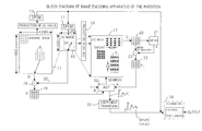
- FIG. 1 is a block diagram showing a conventional image encoder.
- 11 is an original image memory for storing an original image data
- 12 is a DC value production unit for seeking a block average (DC) value per each pixel block (4 times 4 pixel) of the original image data
- 13 is a differential PCM encoding unit (DPCM) for carrying out a differential predict encoding per each DC value
- 14 is inverse DPCM encoding unit for decoding each DC value from the differential PCM encoding
- 15 is a DC image memory for storing a decoded DC image
- 16 is a DC nest production unit for cutting off the DC nest of a desired size from a part of the DC image
- 17 is a DC nest memory for storing the DC nest.
- 18 is a subtractor for separating a corresponding decoding DC value “DC J ” from a target image block ⁇ R J > to be encoded
- 19 is a differential vector buffer for storing a differential vector ⁇ d J > which is DC separated
- 20 is an extracted block buffer for storing a base extraction block ⁇ U i > of 4 times 4 pixels which is down-sampled from the DC nest
- 21 is an equilibrator for seeking a block mean value a i of the base extraction block ⁇ U i >
- 22 is a subtractor for separating the block means value a i from the base extraction block ⁇ U i >
- 23 is an extracted vector buffer for storing the base extraction block ⁇ U i > which is separated by the mean value
- the block mean value of 4 times 4 pixels is provided in which the first decimal place is rounded off or down.
- the quantization coefficient Q(Z) corresponds to the allowable error Z and is variable within the range of 1 to 8 according to the allowable error Z.
- the DC nest is prepared by copying the range of vertical 39 ⁇ horizontal 71 from the DC image. It is preferred that the DC nest includes more alternating current components because it is used as a codebook. Therefore, it is prepared by copying such the range that the sum of absolute values of difference between the DC values adjacent to each other in a plurality of the extracted ranges become maximum.
- a vertex per one DC value in vertical and horizontal section is set to (p x , p y ) ⁇ [0, 63] ⁇ [0, 31] and a distance of its sub-samples is set to 4 kinds of (s x , s y ) ⁇ ⁇ (1, 1), (1, 2), (2, 1), (2, 2) ⁇ .
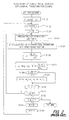
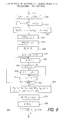
- FIG. 2 is a flow chart of conventional adaptive orthogonal transform processing and FIG. 3 is an image drawing of the processing.
- the square norm ⁇ d j ⁇ 2 of the differential vector is more than Z.
- the square norm ⁇ d j ⁇ 2 of the differential vector is set in a resister E.
- much value e.g. 100,000
- step S 124 the base extraction vector ⁇ u i > is produced by separating the block mean value a i from the base extraction blocks ⁇ U i >. Since the operation or calculation is carried out under the accuracy of integer level, any value of first decimal place in the block mean value a i is rounded off or down.
- step S 125 the base extraction vector ⁇ u i > is subjected to orthogonal transform processing to be converted to the orthogonal basis vector ⁇ u k ′>, if necessary (k>1).
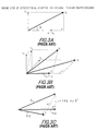
- FIG. 3 (A) and (B) are image drawings of the orthogonal transform processing.
- the first base extraction vector ⁇ u 1 > can be the first basis vector ⁇ u 1 ′> as it is.
- the second base extraction vector ⁇ u 2 > is subjected to orthogonal transform processing to be converted to the second basis vector ⁇ u 2 ′> in accordance with the following method. That is, a shadow of the second base extraction vector ⁇ u 2 > projected on the first basis vector ⁇ u 1 ′> is represented by the formula (1).
- the second orthogonal vector ⁇ u 2 ′> is obtained by subtracting the vector of the projected shadow from the second base extraction vector ⁇ u 2 >.
- u 2 ′ u 2 - ⁇ u 1 ′ ⁇ u 2 ⁇ ⁇ u 1 ′ ⁇ ⁇ ⁇ u 1 ′ ⁇ u 1 ′ ⁇ ( 2 )
- the third base extraction vector ⁇ u 3 > is subjected to orthogonal transform processing to the first basis vector ⁇ u 1 ′> and the second basis vector ⁇ u 2 ′>.
- FIG. 3 is three-dimensionally drawn.
- the third base extraction vector ⁇ u 3 > is subjected to orthogonal transform processing to the first basis vector ⁇ u 1 ′> to obtain an intermediate orthogonal vector ⁇ u 3 ′′>.
- u 3 ′′ u 3 - ⁇ u 1 ′ ⁇ u 3 ⁇ ⁇ u 1 ′ ⁇ 2 ⁇ u 1 ′ ( 3 )
- the intermediate orthogonal vector ⁇ u 3 ′′> is subjected to orthogonal transform processing to the second basis vector ⁇ u 2 ′> to obtain the third basis vector ⁇ u 3 ′>.
- step S 126 a scalar coefficient ⁇ i is calculated using the orthogonal vector ⁇ u i ′> so that a distance with the differential vector ⁇ d k > (at first ⁇ d j >) becomes minimum.
- FIG. 3 (C) is an image drawing of the orthogonal transform processing.
- a differential vector represented by ⁇ d k > is subjected to approximation
- the scalar coefficient ⁇ i is obtained by the formula (5).
- the first base extraction vector ⁇ u j ′> is shown by the image drawing because it can take optional directions.
- step S 128 of FIG. 2 it is judged whether e i is less than E′ or not. If e i is less than E′, content of E′ is renewal in step S 129 and the information regarding ⁇ i , ⁇ u i ′>, ⁇ u i >, etc. at the time is held in an arrangement [ ⁇ k ], [u k ′], [u k ], etc. If e i is not less than E′, the processing in step S 129 is skipped.
- step S 131 The processing is repeated and when it is judged in step S 131 that i is not less than N, all base extraction vectors ⁇ u i > have been completely tried. At the time, the register E′ holds the minimum square norm e i .
- the block mean value a i of the base extraction block ⁇ U i > has been rounded off or down in the conventional methods and therefore, improvement of image quality is limited. Why the conventional methods are inconvenient will be explained according to FIG. 4 .
- FIG. 4 is an image drawing of mean value separation processing.
- a relationship of base extraction block ⁇ U i > (vertical axis) with the pixel value of certain row (horizontal axis) is shown in FIG. 4 ( a ).
- An actual pixel value is a block mean value of 16 pixels, but the block mean value of 4 pixels will be used to simplify the explanation herein.
- each pixel value is 5, 2, 4, and 3 and its mean value a i is 3.5, when the first decimal place is round down, the block mean value a i of the base extraction block ⁇ u i > is 0.5 as shown in FIG. 4 ( b ).
- FIG. 14 ( a ) each pixel value is 5, 2, 4, and 3 and its mean value a i is 3.5, when the first decimal place is round down, the block mean value a i of the base extraction block ⁇ u i > is 0.5 as shown in FIG. 4 ( b ).
- FIG. 14 ( a ) each pixel value is 5, 2,
- the image encoding method of the invention ( 1 ) comprises producing a DC image composed of each block mean value by dividing an image data per B pixel into a block, making a part of said DC image a DC nest, and where the differential vector ⁇ d j > which is obtained by separating the DC value DC J from the pixel block to be encoded is over an allowable value Z, calculating one or more orthogonal basis (e.g.
- any fraction less than 1 does not occurs in the block mean value a i and the block mean value a i with integer level precision is obtained at high speed.
- the lowest n bits of the DC pixel is set to 0 or is masked, where the DC nest is produced from the DC image.
- the DC nest of which the lowest n bits of the DC pixel is set to 0 or is masked, is efficiently obtained by one processing.
- a base extraction vector ⁇ u i > is produced to which the differential vector ⁇ d j > approximates by separating the block mean value a i from the base extraction block ⁇ U i > in which the lowest n bits of the DC pixel is set to 0.
- the sum (the block mean value) of all elements in such base extraction vectors ⁇ u i > is always 0 and the DC component is completely separated. Therefore, even if the base vectors ⁇ u k > are piled up on each other in the decoding side, unnecessary DC component (noise) does not cause.
- the image quality in the HVQ system is more improved by the invention ( 3 ).
- optional elements e.g. u 16 of base extraction vectors ⁇ u i > are replaced by linear bond of the remainder elements and the inner product of the base extraction vectors ⁇ u i > and the other optional vectors ⁇ w> are calculated by the formula.
- ⁇ w ⁇ u i > ( w 1 ⁇ w 16 ) u i +( w 2 ⁇ w 16 ) u 2 + . . . +( w 15 ⁇ w 16 ) u 15
- the sum of all elements in the base extraction vectors ⁇ u i > is always 0 and hence, the optional elements (e.g. u 16 ) are represented by the linear bond of the remainder elements. Accordingly, the inner product calculation ⁇ w ⁇ u i > with the other optional vectors (w) can be expanded to the product-sum calculation as shown by the above formula, whereby a single round of such complicated calculation can be omitted. Since much inner product calculation of the vectors is conducted in the image encoding method according to the HVQ system, such single round omission of the calculation contributes to high speed encoding processing.
- a first basis is searched so that h i may be maximum in the following formula
- ⁇ d> is the differential vectors and ⁇ u i > is the base extraction vectors.
- h i ⁇ d ⁇ u i > ⁇ ( ⁇ d ⁇ u 1 > ⁇ u 1 ⁇ u i >/ ⁇ u 1 ⁇ 2 ) 2 / ⁇ u i ⁇ 2 ⁇ ( ⁇ u 1 ⁇ u i >)/ ⁇ u 1 ⁇ 2 ⁇
- ⁇ d> is the differential vectors
- ⁇ u 1 > is the base extraction vectors corresponding to the first basis
- ⁇ u i > is the base extraction vectors for searching the second basis in the invention ( 3 ) or ( 4 ).
- the AOT processing can be done more efficiently and at higher speed in addition to the advantages of the invention ( 5 ), because the calculation result which has been obtained in the first basis search can be used with respect to ⁇ d ⁇ u 1 > and ⁇ u 1 ⁇ of the numerator, and ⁇ u i ⁇ 2 and ⁇ u 1 ⁇ of the denominator.
- h i may be maximum in the following formula
- h i ( ⁇ d ⁇ u i > ⁇ d ⁇ v 1 > ⁇ v 1 ⁇ u i > ⁇ d ⁇ v 2 > ⁇ v 2 ⁇ u 1 >) 2 / ⁇ u i ⁇ 2 ⁇ v 1 ⁇ u i > 2 ⁇ v 2 ⁇ u i > 2 ⁇
- ⁇ d> is the differential vectors
- ⁇ v 1 > is the first orthonormal base vectors
- ⁇ v 2 > is the second orthonormal base vectors
- ⁇ u i > is the base extraction vectors for searching the third basis.
- the AOT processing can be done more efficiently and at higher speed in addition to the advantages of the invention ( 5 ) and ( 6 ), because the calculation result which has been obtained in the first and second basis search can be used with respect to ( ⁇ d ⁇ u i > ⁇ d ⁇ v 1 > ⁇ v 1 ⁇ u i >) of the numerator, and ( ⁇ u i ⁇ 2 ⁇ v 1 ⁇ u i > 2 ) of the denominator.
- the base extraction vectors ⁇ u i > which match with search conditions are subjected to orthogonal transform with one or more preceding orthonormal basis.
- the norm of each scalar expansion coefficient ⁇ 1 ⁇ m is rearranged in decreasing order, a difference (including 0) between norms adjacent to each other is calculated, and Huffman coding is applied to the obtained difference.
- each scalar expansion coefficient ⁇ 1 ⁇ m can take various value.
- each difference is often similar to or same as each other. The more encoding compression is possible by applying the Huffman coding to the difference value.
- image data ⁇ R j > of coding objective block is encoded instead of the coding of the basis, where the basis is more than certain number. Accordingly, the decoded image quality is improved. In practical, it does not affect the coding compression ratio because such situation is little.
- any fraction less than 1 does not occurs in the block mean value and the block mean value with integer level precision is obtained at high speed.
- the lowest n bits of each selected block (U k ) are set to 0, and hence, even if these are accumulated and added, the addition result becomes multiple of integer of the block size B (e.g. 16).
- the lowest n bits of each DC pixel is set to 0, where DC nests are produced from the DC image, whereby processing is effectively carried out.
- AOT adaptive orthogonal transform
- the recording medium of the invention ( 16 ) comprises a computer readable recording medium storing a program to make a computer to implement the processing described in one of the invention ( 1 ) to ( 13 ).
- FIG. 1 is a block diagram showing a conventional image encoder
- FIG. 2 is a flow chart of a conventional adaptive orthogonal transform processing
- FIG. 3 is an image drawing of the conventional adaptive orthogonal transform processing
- FIG. 4 is an image drawing of a conventional mean value separation processing
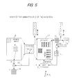
- FIG. 5 is an explanatory drawing of the principle of the invention.
- FIG. 6 is a block diagram showing an image encoder, which is an embodiment of the invention.
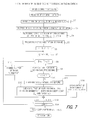
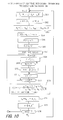
- FIG. 7 is a flow chart showing a main image encoding processing which is an embodiment of the invention.
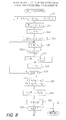
- FIG. 8 is a flow chart ( 1 ) showing an adaptive orthogonal transform processing which is an embodiment of the invention
- FIG. 9 is a flow chart ( 2 ) showing an adaptive orthogonal transform processing which is an embodiment of the invention.
- FIG. 10 is a flow chart ( 3 ) showing an adaptive orthogonal transform processing which is an embodiment of the invention.
- FIG. 11 is an explanatory drawing ( 1 ) of a DC nest, which is an embodiment of the invention.
- FIG. 12 is an explanatory drawing ( 2 ) of a DC nest, which is an embodiment of the invention.
- FIG. 13 is an image drawing of a compression encoding processing of the expansion coefficient
- FIG. 14 is ablock diagram showing an image decoder, which is an embodiment of the invention.
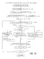
- FIG. 15 is a flow chart showing an image decoding processing which is an embodiment of the invention.
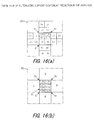
- FIG. 16 is an image drawing of an alternating current component prediction, which is an embodiment of the invention.
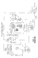
- FIG. 6 which is a block diagram showing an embodiment of image encoding apparatus in the invention
- 31 is a DC nest production unit which produces the DC nest from a decoding DC image according to the invention
- 17 is a DC nest memory which stores the produced DC nest
- 32 is an adaptive orthogonal transform (AOT) processing unit which effectively implements AOT processing at high speed
- 33 is a coefficient transform unit
- 34 is an encoding unit which can make an expanding coefficient ⁇ k higher compression.
- AOT adaptive orthogonal transform
- an original image data is input in a original image memory 11 at step S 1 .
- an objective image of R.G.B. is converted to an image of Y.U.V., which is input in the memory 11 .
- Y is a brightness data
- U and V are color difference data.
- U and V are down-sampled using a brightness mean of 2 pixels in a horizontal direction.
- the brightness data Y is composed of vertical 960 ⁇ horizontal 1280 pixels and, for example, 8 bits are allotted to each pixel.
- the processing of the brightness data Y will be mainly explained in the following but U and V are similarly processed.
- a block mean (DC) value of every 4 ⁇ 4 pixels with respect to all image data is calculated at step S 2 .
- the first decimal place is round off at the time.
- All DC values are encoded by conventional two-dimensional DPCM method, etc. and are output at step S 3 .
- all DPCM outputs are decoded by IDPCM method to reproduce the DC images, which are stored in a DC image memory 15 . This is done to equalize AOT processing conditions in the encoding side with that in the decoding side.
- the DC nest is reproduced from the DC images in the DC nest production unit 31 , which is stored in the DC nest memory 17 .
- a range from which the DC nest is cut can be selected by the same manner as conventional one.
- the lowest 4 bits of each DC pixel DC J cut from the DC image memory 15 are masked (are set to 0) which are stored in a nest pixel N J of the DC nest memory 17 .
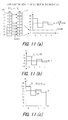
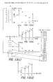
- the sum of base extraction block ⁇ U i > is always multiple of integer and a block mean value a i which is ⁇ fraction (1/16) ⁇ of the sum is always an integer.
- the base extraction vectors ⁇ u i > which are obtained by separating the block mean value a i from the base extraction block ⁇ U i > are always 0.
- FIGS. 11 ( a ) and ( b ) graphs of concrete values are shown as example, in which mean of 4 pixels is used for simplifying the explanation.
- FIG. 11 ( c ) even if a plurality of basis vectors ⁇ k ⁇ u k > are cumulatively added to the DC pixel DC J of a decoding block ⁇ R j >, a noise is not overlapped as usual because the block mean value of each basis vectors ⁇ k ⁇ u k > is always 0, whereby image quality can be much improved.
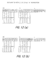
- FIG. 12 ( a ) The examples of the value in FIG. 11 are shown in FIG. 12 ( a ).
- Each element a to d of the base extraction vectors ⁇ u i > which is obtained by separating the mean value 56 of the nest pixels from the nest pixels becomes 24, ⁇ 24, 8 and ⁇ 8, respectively.
- the sum of these elements is 0 (complete mean value separation).
- each element a to d of the base extraction vectors ⁇ u i > which is obtained by separating the mean value 60 of the nest pixels from the nest pixels A to D becomes 33, ⁇ 25, 13 and ⁇ 10, respectively. The sum of these elements is not 0 (complete mean value separation).
- the lowest 4 bits may be masked from each pixel when the base extraction block ⁇ U i > is down-sampled from the DC nest.
- each index counter j, J to the original image memory 11 and the DC image memory 15 is initialized to 0 at step S 6 , wherein j indicates an index counter of the target block ⁇ R j > which is encoding object, and J indicates an index counter of the DC pixel.
- the differential vector ⁇ d j > is obtained by separating a corresponding decoding DC value DC f from the target block ⁇ R j >.
- the target block ⁇ R j > is decoded by alternating current component prediction method as described hereinafter.
- ⁇ d j ⁇ 2 is more than Z
- the adaptive orthogonal transform (AOT) processing method as described hereinafter is carried out at step S 9 .
- step S 12 the basis number m, the expanding coefficient ⁇ k and the index information i of non-orthogonal basis vector ⁇ u i > each is code-output at step S 12 .
- step S 13 “1” is added to the counters j and J, respectively.
- an addition of 1 to the counter j means renewal of onepixel block.
- step S 14 It is judged at step S 14 whether j is not less than M (the number of all image blocks) or not. In case that j is less than M, turning to step S 7 and same encoding processing is repeated with respect to a next target block ⁇ R j >, followed by same steps. It is judged at step S 14 that j is not less than M, then encoding processing, for example, by Huffman method is carried out at step S 15 as described hereinafter. Thus, encoding processing of one pixel is terminated.
- a search processing of first basis is shown in FIG. 8 .
- the first basis is usually obtained as base extraction vector ⁇ u j >, which makes a square norm e i of the difference between the first basis and a differential vector ⁇ d> minimum, and is represented by the formula (7).
- the first item ⁇ d ⁇ 2 of the right side in the formula (7) which is more than 0 is independent of an extracted basis and hence, ⁇ u i > that makes the second item of the right side in the formula (7) maximum can be the first basis.
- the second item h i of the right side is represented by the formula (8).
- step S 22 A processing for searching and judging the first basis ⁇ k ⁇ v k > which makes h i maximum is explained.
- the fifteen dimensional vector ⁇ d′> is obtained by subtracting the sixteenth component of ⁇ d> from the remaining components as a preprocessing to inner product calculation ⁇ d ⁇ u i > as described hereinafter.
- ⁇ u i > is sixteen dimensional vector, but its sixteenth component u 16 can be represented by linear bond of the remaining fifteen components because the block mean value (sum of all elements) is 0.
- the inner product ⁇ d ⁇ u i > of h i numerator can be calculated from ⁇ d′ ⁇ u i > equivalent thereto, whereby one product/sum calculation can be omitted which corresponds to 8192 calculations with respect to total of i.
- step S 28 1 is added to i and at step S 29 , it is judged whether i is not less than N (total extraction numbers) or not. In case that i is less than N, turning to step S 25 and maximum value search processing is carried out with respect to next h i similar to above.
- the second basis is usually obtained as orthogonal vector ⁇ u j ′> which makes a square norm e i of the difference between the second basis and a differential vector ⁇ d 1 > minimum, and is represented by the formula (12).
- the orthogonal vector ⁇ u i ′> is obtained by orthogonal transform of the second base extraction vector ⁇ u i > to the first normalized basis vector ⁇ v 1 >.
- the first item ⁇ d ⁇ 2 of the right side in the formula (12) which is more than 0 is independent of an extracted basis and hence, ⁇ u i ′> that makes the second item of the right side in the formula (12) maximum can be the second basis.
- the second item h i of the right side is represented by the formula (14).
- h i can be calculated but the denominator of the formula (14) may be transformed in order to effectively utilize the calculation result in FIG. 8 . That is, if the orthogonal vector ⁇ u i ′> of the h i numerator is represented by the base extraction vector ⁇ u i >, the h i numerator can be represented by the formula (15).
- the h i numerator can be represented by the formula (16).
- the calculation result ⁇ d ⁇ u 1 > which is obtained in the search of the first basis can be used for calculation of the h i numerator. Also, when the h i denominator is transformed, it can be represented by the formula (17).
- the calculation result ⁇ u i ⁇ 2 , ⁇ u 1 ⁇ which is obtained in the first basis search can be used in the calculation of the h i numerator.
- h i When h i is placed in the formula (14), it can be represented by the formula (18-1) and finally by the formula (18-2).
- h i ( ⁇ d ⁇ u i ⁇ - ⁇ d ⁇ u 1 ⁇ ⁇ u 1 ⁇ ⁇ ⁇ ⁇ u 1 ⁇ u i ⁇ ⁇ u 1 ⁇ ) 2 ⁇ u i ⁇ 2 - ( ⁇ u i ⁇ u 1 ⁇ ⁇ u 1 ⁇ ) 2 (18-1)
- ⁇ ( P - P k I k ⁇ ⁇ ⁇ u k ⁇ u i ⁇ L k ) 2 L i - ( ⁇ u k ⁇ u i ⁇ L k ) 2 ⁇ (18-2)
- the numeral “1” of P 1 means the first basis ⁇ u 1 > in the index counter i and is held in an arrangement [I k ] at step S 27 .
- a calculation is carried out by the formula (19) and a result is stored in a register ⁇ , ⁇ .
- the fifteen dimensional vector ⁇ w 1 > is obtained by subtracting the sixteenth component of ⁇ u 1 > from the remaining components as the preprocessing of inner product calculation ⁇ u 1 ⁇ u i > as described below.
- the calculation result at step S 45 is stored in (written in over) an arrangement [P i ], whereby contents of the arrangement [P i ] are gradually renewed on the past calculation result.
- L i in the right side is a result of the calculation at step S 23 .
- the calculation result at step S 46 is stored in and written in over an arrangement [L i ] at step S 23 , whereby contents of the arrangement [L i ] are gradually renewed on the past calculation result.
- the repeated calculation of h i is finally represented by the formula (20).
- the ortho normalization of the basis vector ⁇ u 2 > and the calculation of the scalar coefficient ⁇ 2 are carried out at one time with respect to the above search result, whereby the AOT processing is much simplified at high speed.
- the third basis is usually obtained as orthogonal vector ⁇ u j ′> which makes a square norm e i of the difference between the second basis and a differential vector ⁇ d 2 > minimum, and is represented by the formula (21).
- the orthogonal vector ⁇ u i ′> is obtained by orthogonalization of the third base extraction vector ⁇ u i > to the first normalized basis vector ⁇ v 1 > and the second normalized basis vector ⁇ v 2 >.
- the first item ⁇ d 2 ⁇ 2 of the right side in the formula (21) which is more than 0 is independent of an extracted basis and hence, ⁇ u i ′> that makes the second item of the right side in the formula (21) maximum becomes the third basis.
- the second item h i of the right side is represented by the formula (23).
- the h i numerator can be represented by the formula (24).
- the h i numerator can be represented by the formula (25).
- h i ( ⁇ d ⁇ u i ⁇ - ⁇ d ⁇ v 1 ⁇ ⁇ ⁇ ( v 1 ⁇ u i ) - ⁇ d ⁇ v 2 ⁇ ⁇ ⁇ v 2 ⁇ u i ⁇ ) 2 ⁇ u i ⁇ 2 - ⁇ u i ⁇ v 1 ⁇ 2 - ⁇ u i ⁇ v 2 ⁇ 2
- h i is represented by the formula (29) in the same manner as in the formula (18-2).
- the formula (29) is same form as the formula (18-2) except that the inner product ⁇ u k ⁇ u i > is changed to ⁇ v k ⁇ u i >. Accordingly, each basis hereinafter can be effectively obtained by repeating the same operation as in FIG. 5 .
- step S 62 calculation is carried out according to the formula (30) and a result is stored in the registers ⁇ and ⁇ .
- the fifteen dimensional vector ⁇ w 2 > is obtained by subtracting the sixteenth component of ⁇ v 2 > from the remaining components as the preprocessing of inner product calculation ⁇ v 2 ⁇ u i > as described below. Since each component of ⁇ v 2 > is not an integer, it is necessary that an inner product is calculated in the form of real number. In order to avoid the calculation in the form of real number, each component of ⁇ v 2 > (i.e. ⁇ w 2 >) is multiplied by a constant “a” to make it an integer, in advance.
- the calculation of the formula (29) is represented by the formula (31).
- the third basis vector ⁇ u 3 > is subjected to orthonormal transform with ⁇ v 1 > and ⁇ v 2 > to be a normalized basis vector ⁇ v 3 > which is stored in an arrangement [V k ].
- a scalar coefficient ⁇ 3 which is a shadow of ⁇ d 2 > projected to ⁇ v 3 > is calculated and is stored in an arrangement [A k ].
- the AOT processing can be much simplified can be carried out at high speed by the above processing or operation.
- the actual calculation time is reduced to 1 ⁇ 3 to ⁇ fraction (1/10) ⁇ in comparison with conventional methods.
- both sides of the formula (33) is multiplied from the left by a transposed matrix U T of the matrix U as shown by the formula (34).
- the matrix (U T U) is expanded to be the formula (35).
- ⁇ u i ⁇ u j > means an inner product, and a square matrix which is a symmetrical to a diagonal element is obtained because ⁇ u i ⁇ u j > is equal to ⁇ u j ⁇ u i >, and an inverse matrix exists because ⁇ u i > is different from ⁇ u j >. Therefore, the inverse matrix (U T U) ⁇ 1 of the matrix (U T U) is multiplied from the left of both sides of the formula to obtain the formula (36) and ⁇ k is calculated.
- each base extraction vector ⁇ u k > is subjected to orthogonal transform in decoding side every time, and the differential vector ⁇ d j > can approximate by adding a multiplied value of them and ⁇ k .
- the decoding processing can be simply carried out at high speed.
- FIG. 13 is an image drawing of a compression encoding processing of the expansion coefficient.
- a norm is extracted from the produced ⁇ 1 ⁇ 4 .
- a norm is arranged, for example, in ascending order ( ⁇ 3 , ⁇ 2 , ⁇ 4 , ⁇ 1 ) and a difference ( ⁇ 3 , ⁇ 2 , ⁇ 4 , ⁇ 1 ) is calculated.
- the upper bits are separated by removing the lowest two bits from all bits in the difference of coefficient ( ⁇ 3 , ⁇ 2 , ⁇ 4 , ⁇ 1 ) and are subjected to Hoffman encoding.
- the output is carried out in the order of ⁇ 3 , ⁇ 2 , ⁇ 4 and ⁇ 1 (i.e. u 3 , u 2 , u 4 , u 1 ).
- each code sign is input in the order of u 3 , u 2 , u 4 and u 1 in decoding side, from which each of the coefficient ⁇ 3 , ⁇ 2 , ⁇ 4 and ⁇ 1 is separated. Further, ⁇ 3 is decoded from the first ⁇ 3 , ⁇ 2 is decoded by adding ⁇ 2 to the decoded ⁇ 3 , ⁇ 4 is decoded by adding ⁇ 4 to the decoded ⁇ 2 , and then ⁇ 1 is decoded by adding ⁇ 1 to the decoded ⁇ 4 .
- the decoding order is not important because ⁇ k ⁇ u k > is functioned based on the sum (linear bond) of these values.
- the difference can be calculated by arranging the norm in descending order instead of the ascending order.
- a prediction difference ⁇ DC J, I of DPCM is quantized by a quantization coefficient Q (Z), and only in case that ⁇ DC J, I is 0, run length coding is considered, and the prediction difference ⁇ DC J,I and the run length coding each is independently subjected to Huffman coding. Only in case that the basis number k is 0, the run length coding is considered, and the basis number k and the run length each is independently subjected to Huffman coding.
- the coefficient difference ⁇ k is quantized by a constant number Q (e.g. 8) to obtain its quotient, which is subjected to Huffman coding.
- row of the coding sign is constituted by incorporating these in appearing order per unit of pixel block. If necessary, a sign EOB is input to show change of pixel blocks.
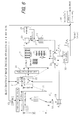
- FIG. 14 is a block diagram showing an image decoder, which is an embodiment of the invention, and corresponds to the image encoder as shown in FIG. 6 .
- 41 is a decoding unit by Huffman, etc.
- 42 is an alternating current component prediction unit for predicting target blocks ⁇ R j > containing the alternating current component from the surrounding DC values DC J ′ containing the noticeable pixels DC J
- 44 is the R j reproduction unit for reproducing target blocks ⁇ R j > based on the decoding blocks ⁇ R j >
- 45 is the reproduced image memory
- 46 is the IDPCM unit for IDPCM decoding the decoded DC value
- 47 is the DC image memory for storing the DC nest
- 48 is the DC nest production unit which is same as in FIG.
- 49 is the DC nest memory for storing the DC nest
- 50 is the selected block buffer for holing the selected blocks ⁇ U k > which are down-sampled from the DC nest
- 51 is a multiplier for multiplying ⁇ U k > by ⁇ k
- 54 is a means for obtaining a block mean value A j of cumulative addition values
- 55 is a subtractor for separating the block mean value A j of cumulative addition values
- 56 is an approximate vector buffer for holding reproduced approximate differential vector ⁇ d j >
- 57 is a means for adding the reproduced approximate differential vector ⁇ d j >.
- the image coding data is input at step S 101 .
- each DC value in Y, U and V is decoded by IDPCM method similar to FIG. 6 and DC images are reproduced.
- DC nest is produced from the DC value of Y component.
- the lowest four bits of each DC pixel value DC J are masked to be each DC nest pixel value N J .
- the information such as cut position of the DC images is separately received.
- the index counters j and J to the original image memory 45 and DC image memory 47 are initialized to 0.
- step S 105 coding data of one block image is input.
- step S 106 it is judged that k is 0 or not. In case that k is 0, the target blocks ⁇ R j > are reproduced by alternating current prediction method as described hereinafter. In case that k is not 0, it is judged at step S 107 whether k is not less than 1 and not more than 4 or not.
- the differential vector ⁇ d j > is inversely quantized at step S 112 . Since the lowest four bits of the DC nest are previously masked in the embodiment of the invention, the differential vector ⁇ d j > is obtained at once by cumulatively adding the product of the selected block ⁇ U k > and ⁇ k and by separating the block mean value A j from the cumulative addition result, whereby the decoding processing is carried out at high speed. At step S 113 , the DC value DC J corresponding to thus obtained differential vector ⁇ d j > is added.
- the target blocks ⁇ R j > are directly produced from the decoding data of the target blocks ⁇ R j > at step S 108 .
- the target blocks ⁇ R j > of 4 times 4 pixels are reproduced by any methods as above.
- the reproduced target blocks ⁇ R j > are stored in the reproduced image memory 45 at step S 109 .
- step S 110 “1” is added to the counters j and J, respectively, and at step S 111 , it is judged whether i is not less than M (all pixel block numbers) or not. In case that i is less than M, turning to step S 105 and the decoding and reproducing processing is carried out with respect to subsequent the block image coding data. When the same procedure was proceeded and j is not less than M in the judge at step S 111 , the decoding processing per one image is terminated.
- FIG. 16 is an image drawing of an alternating current component prediction, which is an embodiment of the invention and is applicable for conventional prediction methods.
- FIG. 16 (A) is a stepwise alternating current component prediction method as described hereinafter.
- each sub-block S 1 ⁇ S 4 is predicted from each DC value of the 4 blocks (U, R, B, L) surrounding the S 1 ⁇ S 4 .
- U 1 ⁇ U 4 , L 1 ⁇ L 4 , R 1 ⁇ R 4 and B 1 ⁇ B 4 are predicted at the first stage.
- 4 pixels P 1 ⁇ P 4 on S 1 are predicted by using the above method repeatedly.
- Each 4 pixels P 1 ⁇ P 4 on S 2 ⁇ S 4 are predicted in the same manner.
- the target blocks ⁇ R j > are reproduced by such two stage processing.
- FIG. 16 (B) is a non-stepwise alternating current component prediction method, which the applicant has been already proposed.
- each of the 4 pixels P 1 ⁇ P 4 on each of the sub-block S 1 ⁇ S 4 is predicted from each DC value of 4 blocks surrounding the noticeable block S at a stroke.
- each approximation of S 2 ⁇ S 3 ⁇ S, U 3 ⁇ U 2 and L 2 ⁇ L is carried out to obtain each4 pixels P 1 ⁇ P 4 on S 1 .
- the approximation is applied to P 1 ⁇ P 4 on S 1 to obtain the formula,
- Each 4 pixels P 1 ⁇ P 4 on S 2 ⁇ S 4 is obtained in the same manner.
- high image quality can be obtained by the improvement of the DC nest and high speed encoding can be achieved by the means for the AOT calculation. Therefore, the method of the invention much contributes to the attainment of high image quality and high speed encoding in the HVQ system.
Landscapes
- Engineering & Computer Science (AREA)
- Multimedia (AREA)
- Signal Processing (AREA)
- Physics & Mathematics (AREA)
- General Physics & Mathematics (AREA)
- Theoretical Computer Science (AREA)
- Compression Or Coding Systems Of Tv Signals (AREA)
- Compression Of Band Width Or Redundancy In Fax (AREA)
- Compression, Expansion, Code Conversion, And Decoders (AREA)
Priority Applications (1)
| Application Number | Priority Date | Filing Date | Title |
|---|---|---|---|
| US10/760,291 US7231089B2 (en) | 2000-05-15 | 2004-01-21 | Image encoding/decoding method, apparatus thereof and recording medium in which program therefor is recorded |
Applications Claiming Priority (2)
| Application Number | Priority Date | Filing Date | Title |
|---|---|---|---|
| JP2000141675A JP3932244B2 (ja) | 2000-05-15 | 2000-05-15 | 画像符号/復号方法及びその装置並びにそのプログラムを記録した記録媒体 |
| JP2000-141675 | 2000-05-15 |
Related Child Applications (1)
| Application Number | Title | Priority Date | Filing Date |
|---|---|---|---|
| US10/760,291 Division US7231089B2 (en) | 2000-05-15 | 2004-01-21 | Image encoding/decoding method, apparatus thereof and recording medium in which program therefor is recorded |
Publications (2)
| Publication Number | Publication Date |
|---|---|
| US20010051005A1 US20010051005A1 (en) | 2001-12-13 |
| US6714687B2 true US6714687B2 (en) | 2004-03-30 |
Family
ID=18648758
Family Applications (2)
| Application Number | Title | Priority Date | Filing Date |
|---|---|---|---|
| US09/731,484 Expired - Fee Related US6714687B2 (en) | 2000-05-15 | 2000-12-08 | Image encoding/decoding method, apparatus thereof and recording medium in which program therefor is recorded |
| US10/760,291 Expired - Fee Related US7231089B2 (en) | 2000-05-15 | 2004-01-21 | Image encoding/decoding method, apparatus thereof and recording medium in which program therefor is recorded |
Family Applications After (1)
| Application Number | Title | Priority Date | Filing Date |
|---|---|---|---|
| US10/760,291 Expired - Fee Related US7231089B2 (en) | 2000-05-15 | 2004-01-21 | Image encoding/decoding method, apparatus thereof and recording medium in which program therefor is recorded |
Country Status (8)
| Country | Link |
|---|---|
| US (2) | US6714687B2 (zh) |
| EP (1) | EP1156679A3 (zh) |
| JP (1) | JP3932244B2 (zh) |
| KR (1) | KR100741553B1 (zh) |
| CN (1) | CN1324060A (zh) |
| CA (1) | CA2328037A1 (zh) |
| MX (1) | MXPA01001104A (zh) |
| TW (1) | TW503666B (zh) |
Cited By (1)
| Publication number | Priority date | Publication date | Assignee | Title |
|---|---|---|---|---|
| US7480584B2 (en) | 2004-01-30 | 2009-01-20 | Canon Kabushiki Kaisha | Coding method and apparatus, and computer program and computer-readable storage medium |
Families Citing this family (8)
| Publication number | Priority date | Publication date | Assignee | Title |
|---|---|---|---|---|
| US7310598B1 (en) * | 2002-04-12 | 2007-12-18 | University Of Central Florida Research Foundation, Inc. | Energy based split vector quantizer employing signal representation in multiple transform domains |
| US7343039B2 (en) * | 2003-06-13 | 2008-03-11 | Microsoft Corporation | System and process for generating representations of objects using a directional histogram model and matrix descriptor |
| KR100612669B1 (ko) | 2003-10-29 | 2006-08-14 | 에스케이 텔레콤주식회사 | 이동 통신 단말에서 고해상도 jpeg 화상을디스플레이하기 위한 방법과 이를 위한 이동 통신 단말 |
| WO2006044276A1 (en) | 2004-10-18 | 2006-04-27 | Thomson Licensing | Methods, apparatus and system for film grain simulation |
| US7864864B2 (en) * | 2005-06-27 | 2011-01-04 | Intel Corporation | Context buffer address determination using a plurality of modular indexes |
| US8968080B1 (en) | 2010-11-05 | 2015-03-03 | Wms Gaming, Inc. | Display of third party content on a wagering game machine |
| US8515179B1 (en) * | 2012-02-10 | 2013-08-20 | Raytheon Company | System and method for hyperspectral image compression |
| EP3657793A4 (en) * | 2017-12-06 | 2021-03-17 | Fujitsu Limited | MODE INFORMATION ENCODING AND ENCODING PROCESS, CORRESPONDING DEVICE AND ELECTRONIC APPARATUS |
Citations (5)
| Publication number | Priority date | Publication date | Assignee | Title |
|---|---|---|---|---|
| US5757969A (en) * | 1995-02-28 | 1998-05-26 | Daewoo Electronics, Co., Ltd. | Method for removing a blocking effect for use in a video signal decoding apparatus |
| US5852682A (en) * | 1995-02-28 | 1998-12-22 | Daewoo Electronics, Co., Ltd. | Post-processing method and apparatus for use in a video signal decoding apparatus |
| US5937098A (en) * | 1995-02-06 | 1999-08-10 | Asahi Kogaku Kogyo Kabushiki Kaisha | Adaptive quantization of orthogonal transform coefficients for setting a target amount of compression |
| WO2000002393A1 (en) | 1998-07-03 | 2000-01-13 | Hudson Co., Ltd. | Image coding/decoding method and recorded medium on which program is recorded |
| US6477276B1 (en) * | 1997-11-07 | 2002-11-05 | Matsushita Electric Industrial Co., Ltd. | Apparatus for and method of embedding and extracting digital information and medium having program for carrying out the method recorded thereon |
Family Cites Families (6)
| Publication number | Priority date | Publication date | Assignee | Title |
|---|---|---|---|---|
| JPH06253281A (ja) * | 1993-02-24 | 1994-09-09 | Nippon Telegr & Teleph Corp <Ntt> | 画像信号直交変換方法 |
| JPH0738760A (ja) * | 1993-06-28 | 1995-02-07 | Nec Corp | 直交変換基底生成方式 |
| KR0139164B1 (ko) * | 1994-12-19 | 1998-06-01 | 김광호 | 적응적 직교변환부호화 장치 |
| JP3170193B2 (ja) * | 1995-03-16 | 2001-05-28 | 松下電器産業株式会社 | 画像信号の符号化装置及び復号装置 |
| JPH0951504A (ja) * | 1995-08-03 | 1997-02-18 | Matsushita Electric Ind Co Ltd | 画像符号化装置及び画像復号化装置 |
| JP3355964B2 (ja) * | 1996-10-29 | 2002-12-09 | ケイディーディーアイ株式会社 | 適応直交変換モード判定方法 |
-
2000
- 2000-05-15 JP JP2000141675A patent/JP3932244B2/ja not_active Expired - Fee Related
- 2000-12-08 US US09/731,484 patent/US6714687B2/en not_active Expired - Fee Related
- 2000-12-08 CA CA 2328037 patent/CA2328037A1/en not_active Abandoned
- 2000-12-15 KR KR1020000076886A patent/KR100741553B1/ko active IP Right Grant
- 2000-12-20 TW TW89127438A patent/TW503666B/zh not_active IP Right Cessation
-
2001
- 2001-01-30 MX MXPA01001104 patent/MXPA01001104A/es not_active Application Discontinuation
- 2001-02-07 EP EP20010301069 patent/EP1156679A3/en not_active Withdrawn
- 2001-02-17 CN CN01104592A patent/CN1324060A/zh active Pending
-
2004
- 2004-01-21 US US10/760,291 patent/US7231089B2/en not_active Expired - Fee Related
Patent Citations (6)
| Publication number | Priority date | Publication date | Assignee | Title |
|---|---|---|---|---|
| US5937098A (en) * | 1995-02-06 | 1999-08-10 | Asahi Kogaku Kogyo Kabushiki Kaisha | Adaptive quantization of orthogonal transform coefficients for setting a target amount of compression |
| US5757969A (en) * | 1995-02-28 | 1998-05-26 | Daewoo Electronics, Co., Ltd. | Method for removing a blocking effect for use in a video signal decoding apparatus |
| US5852682A (en) * | 1995-02-28 | 1998-12-22 | Daewoo Electronics, Co., Ltd. | Post-processing method and apparatus for use in a video signal decoding apparatus |
| US6477276B1 (en) * | 1997-11-07 | 2002-11-05 | Matsushita Electric Industrial Co., Ltd. | Apparatus for and method of embedding and extracting digital information and medium having program for carrying out the method recorded thereon |
| WO2000002393A1 (en) | 1998-07-03 | 2000-01-13 | Hudson Co., Ltd. | Image coding/decoding method and recorded medium on which program is recorded |
| EP1104199A1 (en) | 1998-07-03 | 2001-05-30 | Hudson Co., Ltd | Image coding/decoding method and recorded medium on which program is recorded |
Non-Patent Citations (4)
| Title |
|---|
| Huang S-C, et al., "A Contrained Vector Quantization Scheme for Real-Time Codebook Retransmission", vol. 4, No. 1, Feb. 1, 1994, pp. 1-7. |
| Patent Abstracts of Japan, Publ. No.: 07038760, Publ. Date: Feb. 7, 1995. |
| Takahashi T, et al., "A Fast Computation Algorithm for Predicting AC Components of Imagesusing Mean Values of Blocks", vol. J81-D-II, No. 4, Apr. 1998, pp. 778-780. |
| You H, et al., "Improving LIFS Image Coding Scheme Via Gram-Schmidt Orthogonalization", IEICE Technical Report, 1998, pp. 37-42. |
Cited By (1)
| Publication number | Priority date | Publication date | Assignee | Title |
|---|---|---|---|---|
| US7480584B2 (en) | 2004-01-30 | 2009-01-20 | Canon Kabushiki Kaisha | Coding method and apparatus, and computer program and computer-readable storage medium |
Also Published As
| Publication number | Publication date |
|---|---|
| CA2328037A1 (en) | 2001-11-15 |
| KR100741553B1 (ko) | 2007-07-20 |
| JP2001326935A (ja) | 2001-11-22 |
| KR20010104610A (ko) | 2001-11-26 |
| EP1156679A2 (en) | 2001-11-21 |
| JP3932244B2 (ja) | 2007-06-20 |
| US7231089B2 (en) | 2007-06-12 |
| US20010051005A1 (en) | 2001-12-13 |
| MXPA01001104A (es) | 2004-08-12 |
| TW503666B (en) | 2002-09-21 |
| US20040151389A1 (en) | 2004-08-05 |
| EP1156679A3 (en) | 2003-10-08 |
| CN1324060A (zh) | 2001-11-28 |
Similar Documents
| Publication | Publication Date | Title |
|---|---|---|
| KR100281165B1 (ko) | 효율적 처리를 위한 데이터의 다중 해상도의 무손실/유손실 압축 및 기억 방법 및 그 시스템 | |
| CN101273639B (zh) | 多维数字信号的滤波方法和设备及相关编解码方法和设备 | |
| KR100574702B1 (ko) | 화상부호/복호방법 및 그 프로그램을 기록한 기록매체 | |
| EP0628232A1 (en) | Fractal coding of data | |
| JP2006502604A (ja) | 任意形状オブジェクトの画像圧縮方法 | |
| US6714687B2 (en) | Image encoding/decoding method, apparatus thereof and recording medium in which program therefor is recorded | |
| JP7233875B2 (ja) | 作成方法、コンピュータ及びプログラム | |
| JP4737665B2 (ja) | 符号処理装置、符号処理方法、プログラム及び情報記録媒体 | |
| JPH0621828A (ja) | ベクトル量子化復号化器 | |
| Shinde et al. | Image Compression of Handwritten Devanagari Text Documents Using a Convolutional Autoencoder | |
| JPH07123276A (ja) | 画像信号のデジタル圧縮符号化方法 | |
| JP2845098B2 (ja) | 多値画像圧縮符号の復号方法および装置 | |
| JP2002077920A (ja) | 画像圧縮装置及び画像圧縮方法 | |
| Markas et al. | Image compression methods with distortion controlled capabilities | |
| JP3977753B2 (ja) | 情報源の符号化方法,情報源の符号化装置,情報源の符号化プログラム,情報源の符号化プログラムを記録した記録媒体 | |
| He et al. | How Can Spiral Architecture Improve Image Compression? | |
| Kamatar et al. | Image Compression Using Mapping Transform with Pixel Elimination | |
| KR100495001B1 (ko) | 이미지 압축 부호화 방법 및 시스템 | |
| Mitra et al. | A New Probabilistic Approach for Fractal Based Image Compression | |
| JP2633683B2 (ja) | ベクトル量子化装置 | |
| JP2693557B2 (ja) | 符号化装置 | |
| JP2003284073A (ja) | 画像符号/復号方法及び装置並びにプログラム及び記録媒体 | |
| US20020094126A1 (en) | Fractal image compression | |
| Srivastava et al. | Wavelet based JPEG like Image Coding Scheme | |
| JPH10290460A (ja) | 画像圧縮方法 |
Legal Events
| Date | Code | Title | Description |
|---|---|---|---|
| AS | Assignment |
Owner name: HUDSON SOFT CO. LTD., JAPAN Free format text: ASSIGNMENT OF ASSIGNORS INTEREST;ASSIGNORS:ITAGAKI, FUMIHIKO;KAWASHIMA, MIYUKI;REEL/FRAME:011669/0811 Effective date: 20010314 |
|
| REMI | Maintenance fee reminder mailed | ||
| LAPS | Lapse for failure to pay maintenance fees | ||
| STCH | Information on status: patent discontinuation |
Free format text: PATENT EXPIRED DUE TO NONPAYMENT OF MAINTENANCE FEES UNDER 37 CFR 1.362 |
|
| FP | Lapsed due to failure to pay maintenance fee |
Effective date: 20080330 |