US6692203B2 - Automatic container locking apparatus for trailers - Google Patents
Automatic container locking apparatus for trailers Download PDFInfo
- Publication number
- US6692203B2 US6692203B2 US10/181,415 US18141502A US6692203B2 US 6692203 B2 US6692203 B2 US 6692203B2 US 18141502 A US18141502 A US 18141502A US 6692203 B2 US6692203 B2 US 6692203B2
- Authority
- US
- United States
- Prior art keywords
- locking bolt
- actuator
- container
- locking
- housing
- Prior art date
- Legal status (The legal status is an assumption and is not a legal conclusion. Google has not performed a legal analysis and makes no representation as to the accuracy of the status listed.)
- Expired - Lifetime
Links
Images


Classifications
-
- B—PERFORMING OPERATIONS; TRANSPORTING
- B60—VEHICLES IN GENERAL
- B60P—VEHICLES ADAPTED FOR LOAD TRANSPORTATION OR TO TRANSPORT, TO CARRY, OR TO COMPRISE SPECIAL LOADS OR OBJECTS
- B60P7/00—Securing or covering of load on vehicles
- B60P7/06—Securing of load
- B60P7/13—Securing freight containers or forwarding containers on vehicles
- B60P7/132—Securing freight containers or forwarding containers on vehicles twist-locks for containers or frames
-
- B—PERFORMING OPERATIONS; TRANSPORTING
- B60—VEHICLES IN GENERAL
- B60P—VEHICLES ADAPTED FOR LOAD TRANSPORTATION OR TO TRANSPORT, TO CARRY, OR TO COMPRISE SPECIAL LOADS OR OBJECTS
- B60P7/00—Securing or covering of load on vehicles
- B60P7/06—Securing of load
- B60P7/13—Securing freight containers or forwarding containers on vehicles
Definitions
- the present invention relates, in general, to an automatic container locking apparatus for trailers and, more particularly, to an automatic container locking apparatus, installed in the deck of a trailer and automatically operable in response to the weight of a container to lock or unlock the container on the deck of the trailer, thus securely and safely holding the container on the deck while transporting the container on a road, and being convenient to workers while loading or unloading the container onto or from the deck of the trailer.
- a container is a large, vanlike, reusable box for consolidating smaller crates or cartons into a single shipment, designed for easy and fast loading and unloading of freight.
- a container is loaded on a trailer, and is transported by a truck tractor on a road
- a plurality of locking apparatuses are installed in the deck at predetermined positions. Such an installation of the locking apparatuses on the deck of a trailer is prescribed by law.
- FIGS. 1 a and 1 b are sectional views, showing an operation of a conventional container locking apparatus for trailers when the locking apparatus locks a container in position on the deck of a trailer.
- the conventional container locking apparatus installed in the deck 1 of a trailer at a predetermined position, comprises a locking bolt 2 .
- This locking bolt 2 is vertically movable and rotatable by an actuation of a lever 3 , thus locking or unlocking a container 4 on the deck 1 .
- the container 4 is primarily seated on the deck 1 at a predetermined position.
- the lever 3 of the locking bolt 2 is manipulated by a worker to fully insert the top head 2 ′ of the locking bolt 2 into a locking hole 5 formed on the bottom of the deck 1 , thus locking the container 4 in position on the deck 1 .
- the locking apparatus holds the container 4 on the deck 1 of the trailer while transporting the container on a road, and prevents the container 4 from being undesirably moved on the deck 1 or unexpectedly dropped from the deck 1 onto the road during such transportation.
- an object of the present invention is to provide an automatic container locking apparatus for trailers, which is installed in the deck of a trailer, and is automatically operable in response to the weight of a container to lock or unlock the container on the deck when it is desired to load or unload the container onto or from the deck.
- the present invention provides an automatic container locking apparatus for trailers, comprising a housing vertically set in the deck of a trailer at a predetermined position, an actuator having a hollow structure with a central opening, the actuator being axially and movably set within the housing while being normally biased upward by a first compression coil spring such that the actuator is vertically extendible and retractable relative to the upper end of the housing, a longitudinal locking bolt having a head at its upper end and movably and concentrically set within the central opening of the actuator such that the locking bolt is removably inserted into a locking hole of a container at the head, with a stopper externally formed on the sidewall of the locking bolt at a predetermined position to selectively come into contact with the lower surface of the actuator, thus allowing the locking bolt to be selectively and vertically movable in conjunction with a vertical movement of the actuator, a hole longitudinally formed at the center of the locking bolt while extending from the lower end of the locking bolt to a predetermined depth, with a first compression coil spring such that the actuator
- FIGS. 1 a and 1 b are sectional views, showing an operation of a conventional container locking apparatus for trailers when the locking apparatus locks a container in position on the deck of a trailer;
- FIG. 2 is an exploded perspective view of an automatic container locking apparatus for trailers in accordance with the preferred embodiment of the present invention
- FIGS. 3 and 4 are a perspective view and a sectional view of the container locking apparatus of this invention, with the parts of the locking apparatus completely assembled into a single body;
- FIGS. 5 a to 5 c are sectional views, showing an operation of the container locking apparatus of this invention when the locking apparatus locks a container in position on the deck of a trailer;
- FIG. 6 is a position of the container locking apparatus of this invention when a container, which does not have any locking hole and is not necessary to be locked to the deck, is seated on the deck;
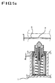
- FIG. 7 is an exploded perspective view of an automatic container locking apparatus for trailers, with a housing of the apparatus altered in its profile in accordance with a modification of the preferred embodiment of this invention.
- FIG. 2 is an exploded perspective view of an automatic container locking apparatus for trailers in accordance with the preferred embodiment of the present invention.
- FIGS. 3 and 4 are a perspective view and a sectional view of the container locking apparatus of this invention, with the parts of the locking apparatus completely assembled into a single body
- the automatic container locking apparatus for trailers of this invention comprises a housing 10 , which is vertically set in the deck of a trailer at a predetermined position.
- a cylindrical actuator 20 having a hollow structure with a stepped central opening 21 formed at the center of the actuator 20 , is axially and movably set within the housing 10 while being normally biased upward by a first compression coil spring 22 such that the actuator 20 is extendible and retractable relative to the upper end of the housing 10
- a longitudinal locking bolt 30 having a head 31 at its upper end, is movably and concentrically set within the central opening 21 of the actuator 20 such that the locking bolt 30 is removably inserted into a locking hole of a container at the head 31 .
- a stopper 32 is externally formed on the sidewall of the locking bolt 30 at a predetermined position to selectively come into contact with the lower surface of the actuator 20 , thus allowing the locking bolt 30 to be selectively and vertically movable in conjunction with a vertical movement of the actuator 20 .
- a hole 40 is longitudinally formed at the center of the locking bolt 30 .
- This hole 40 extends from the lower end of the locking bolt 30 to a predetermined depth
- a guide slit 41 is formed on the sidewall of the locking bolt 30 to communicate with the hole 40 .
- This curved guide slit 41 allows the locking bolt 30 to be rotatable relative to the actuator 20 at a predetermined angle as will be described later herein when the locking bolt 30 is moved in response to external pressure applied downward to the locking bolt 30 .
- a support shaft 50 is axially, upwardly and movably inserted in the hole 40 of the locking bolt 30 from the lower end of the locking bolt 30 , with a second compression coil spring 52 set within the hole 40 at a position between the inside end of the hole 40 and the top end of the support shaft 50 .
- the lower end of the housing 10 is firmly closed by a bottom lid 11 , while the support shaft 50 is fixed to the bottom lid 11 at its lower end.
- An actuation pin 51 is formed on a sidewall of the support shaft 50 at an upper portion, and movably engages with the curved guide slit 41 , thus allowing the locking bolt 30 to be rotatable relative to the actuator 20 at the predetermined angle when the locking bolt 30 is vertically moved.
- FIGS. 5 a to 5 c are sectional views, showing an operation of the container locking apparatus of this invention when the locking apparatus locks a container in position on the deck of a trailer
- the housing 10 of this locking apparatus is set in the deck 1 of a trailer at a predetermined position.
- the actuator 20 and the locking bolt 30 normally biased upward by the first and second compression coil springs 22 and 52 , are elastically and commonly projected upward from the top surface of the deck 1 , thus accomplishing a normal position of the locking apparatus as shown in FIG. 5 a.
- the actuator 20 movably set within the housing 10 , is projected to its fully extended position outside the upper end of the housing 10 due to the restoring force of the first compression coil spring 22 .
- the first spring 22 is set within the housing at a position between the lower surface of the actuator 20 and the bottom lid 11 of the housing 10
- the locking bolt 30 movably set within the actuator 20 , is also projected to its fully extended position outside the upper end of the actuator 20 due to the restoring force of the second compression coil spring 52 .
- the support shaft 50 fixedly standing at the center of the bottom lid 11 , maintains the vertical position of the locking bolt 30 , while the second spring 52 within the hole 40 of the locking bolt 30 biases the locking bolt 30 upward
- the projectional extension of the locking bolt 30 is limited by an engagement of the pin 51 of the support shaft 50 with the guide slit 41 of the locking bolt 30 .
- the head 31 of the locking bolt 30 is completely inserted into the locking hole 5 of the container 4 at the initial stage of loading the container 4 on the deck 1
- the locking apparatus thus accomplishes a primary locking position, at which the stopper 32 comes into contact with the lower surface of the actuator 20 as shown in FIG. 5 b .
- the locking hole 5 formed on the steel plate of the container 4 is designed to have a rectangular profile capable of smoothly passing the head 31 of the locking bolt 30 through it when the head 31 is properly aligned with the hole 5 .
- the locking bolt 30 When downward pressure is further applied from the container 4 to the actuator 20 of FIG. 5 b , the locking bolt 30 is moved downward along with the actuator 20 since the stopper 32 comes into contact with the lower surface of the actuator 20 . During such a downward movement of the locking bolt 30 along with the actuator 20 , the locking bolt 30 is also rotated relative to the actuator 20 at a predetermined angle since the actuation pin 51 of the fixed support shaft 50 movably engages with the curved guide slit 41 of the rotatable locking bolt 30 . The head 31 of the rotated locking bolt 30 thus crosses the rectangular locking hole 5 of the container 4 , and so the container 4 is completely locked to the deck 1 The locking apparatus thus accomplishes a final locking position as shown in FIG. 5 c .
- the rotated angle of the locking bolt 30 relative to the fixed support shaft 50 has to be properly set such that the head 31 crosses the rectangular locking hole 5 of the container 4 . Therefore, the locking apparatus of this invention is automatically operated in response to the weight of the container 4 to lock the container 4 in position on the deck 1 of the trailer.
- FIG. 6 is a position of the container locking apparatus of this invention when a container, which does not have any locking hole and is not necessary to be locked to the deck, is seated on the deck.
- the head 31 of the locking bolt 30 is fully retracted into the housing 10 to allow the lower surface of the container 4 to be stably laid on the top surface of the deck 1 without being interfered with the locking bolt 30 .
- Such a fully retractable structure of the locking bolt 30 also protects the locking bolt 30 from unexpected damage or breakage.
- FIG. 7 is an exploded perspective view of an automatic container locking apparatus for trailers, with a housing of the apparatus altered in its profile in accordance with a modification of the preferred embodiment of this invention
- the housing 10 is designed to have a rectangular cross-section different from the circular cross-section of FIG. 2 .
- the housing 10 may be somewhat freely designed to have another profile in place of such a circular cross-section or rectangular cross-section without affecting the functioning of this invention.
- the locking apparatus When the container 4 is lifted upward from the deck 1 of the trailer to unload the container 4 from the deck 1 , the downward pressure is released from the actuator 20 , and so the locking apparatus automatically returns to its normal position due to the restoring force of the two compression coil springs 22 and 52 . Therefore, it is possible for the locking apparatus to automatically release the container 4 when it is desired to unload the container 4 from the deck 1 .
- the present invention provides an automatic container locking apparatus for trailers
- This automatic container locking apparatus is installed in the deck of a trailer, and is automatically operable in response to the weight of a container to lock or unlock the container on the deck of the trailer. Therefore, the locking apparatus of this invention securely and safely holds the container on the deck while transporting the container on a road, and is convenient to workers while loading or unloading the container onto or from the deck of the trailer.
Abstract
Description
Claims (1)
Applications Claiming Priority (3)
| Application Number | Priority Date | Filing Date | Title |
|---|---|---|---|
| KR2000-4080 | 2000-01-27 | ||
| KR1020000004080A KR100351793B1 (en) | 2000-01-27 | 2000-01-27 | Auto Locking Apparatus of Container For Trailer |
| PCT/KR2001/000082 WO2001054945A1 (en) | 2000-01-27 | 2001-01-18 | Automatic container locking apparatus for trailers |
Publications (2)
| Publication Number | Publication Date |
|---|---|
| US20030063958A1 US20030063958A1 (en) | 2003-04-03 |
| US6692203B2 true US6692203B2 (en) | 2004-02-17 |
Family
ID=19642183
Family Applications (1)
| Application Number | Title | Priority Date | Filing Date |
|---|---|---|---|
| US10/181,415 Expired - Lifetime US6692203B2 (en) | 2000-01-27 | 2001-01-18 | Automatic container locking apparatus for trailers |
Country Status (11)
| Country | Link |
|---|---|
| US (1) | US6692203B2 (en) |
| EP (1) | EP1252040B1 (en) |
| JP (1) | JP3629658B2 (en) |
| KR (2) | KR100351793B1 (en) |
| CN (1) | CN1128730C (en) |
| AT (1) | ATE451274T1 (en) |
| AU (2) | AU2001228897B2 (en) |
| BR (1) | BR0107856B1 (en) |
| DE (1) | DE60140728D1 (en) |
| MX (1) | MXPA02007316A (en) |
| WO (1) | WO2001054945A1 (en) |
Cited By (23)
| Publication number | Priority date | Publication date | Assignee | Title |
|---|---|---|---|---|
| US20040018067A1 (en) * | 2000-07-14 | 2004-01-29 | Taylor Matthew W. | Airlift pallet for container roll-in/out platform (CROP) |
| US20050210636A1 (en) * | 2002-05-30 | 2005-09-29 | Se-Jong Park | Apparatus for automatically locking the ship container |
| US20070212183A1 (en) * | 2006-03-10 | 2007-09-13 | Holland Comapny | Container securement device and system |
| US20090278382A1 (en) * | 2008-05-09 | 2009-11-12 | Union Pacific Railraod Company | Mounting of drag reducing devices for stacked intermodal rail cars |
| US20100124469A1 (en) * | 2008-11-14 | 2010-05-20 | Dianren Zhang | Twistlock |
| US20100326316A1 (en) * | 2009-06-24 | 2010-12-30 | Union Pacific Railroad Company | Drag reducing devices for a locomotive |
| US20110056406A1 (en) * | 2009-02-27 | 2011-03-10 | Union Pacific Railroad Company | Aerodynamic pseudocontainers for reducing drag associated with stacked intermodal containers |
| WO2011066829A1 (en) | 2009-12-01 | 2011-06-09 | 1. Rmm Entwicklungsgesellschaft Mbh & Co. Kg | Locking device for a container |
| US20120024740A1 (en) * | 2009-11-03 | 2012-02-02 | Deutsches Zentrum Fur Luft- Und Raumfahrt E.V. | Container, a transport unit formed by the latter, and a container system |
| US20150001119A1 (en) * | 2013-06-27 | 2015-01-01 | Hong Fu Jin Precision Industry (Shenzhen) Co., Ltd | Connecting device and stackable storage unit with the same |
| US8998271B2 (en) | 2009-02-11 | 2015-04-07 | Illinois Tool Works Inc. | Fixing device for fixing an actuation device with push-push kinematics |
| WO2015126591A1 (en) * | 2014-02-19 | 2015-08-27 | Mi-Jack Products, Inc. | Latching system for automatic securement of a container to a container chassis |
| US9340146B2 (en) | 2014-02-19 | 2016-05-17 | Mi-Jack Products, Inc. | Front pin latching system for automatic securement of a container to a container chassis |
| US9387792B2 (en) | 2014-02-19 | 2016-07-12 | Mi-Jack Products, Inc. | Latching system for automatic securement of a container to a container chassis |
| US9463732B2 (en) | 2014-02-19 | 2016-10-11 | Mi-Jack Products, Inc. | Latching system for automatic securement of a container to a container chassis |
| US20170106966A1 (en) * | 2015-10-15 | 2017-04-20 | Goodrich Corporation | Conformal actuator operated aircraft cargo restraint mechanism |
| US20170158110A1 (en) * | 2015-12-03 | 2017-06-08 | Hyon IL JO | Locking apparatus of container for trailer |
| US20180065535A1 (en) * | 2015-04-09 | 2018-03-08 | Minato Seiki Iron Works Co., Ltd. | Container-securing device |
| US9969318B2 (en) | 2016-04-27 | 2018-05-15 | Mi-Jack Products, Inc. | Locking system for securing a container |
| US10486583B2 (en) * | 2015-12-03 | 2019-11-26 | Yooguneng Co., Ltd. | Multifunctional locking device for container of trailer |
| US20210188152A1 (en) * | 2017-11-10 | 2021-06-24 | Kwanghee HAN | Container binding device |
| US11685353B2 (en) | 2021-01-05 | 2023-06-27 | Mi-Jack Products, Inc. | Systems and method for securement of a container to a vehicle having a brake system |
| US11752924B2 (en) | 2021-01-05 | 2023-09-12 | Mi-Jack Products, Inc. | Latching device and method for automatic securement of a container to a container chassis |
Families Citing this family (24)
| Publication number | Priority date | Publication date | Assignee | Title |
|---|---|---|---|---|
| KR20040015483A (en) * | 2002-08-13 | 2004-02-19 | 손봉률 | Device for fixing container |
| ES1053467Y (en) * | 2002-11-15 | 2003-08-01 | Labraca Carlos Manuel Panos | FIXING DEVICE FOR TRANSPORT CONTAINERS. |
| KR100613443B1 (en) | 2005-06-16 | 2006-08-22 | 대금산업 주식회사 | Locking apparatus of container for a railway vehicle |
| EP2072071A1 (en) * | 2007-12-18 | 2009-06-24 | Sybermat | Syringe nest lid |
| KR101016138B1 (en) * | 2009-11-20 | 2011-02-17 | 조영래 | A container of auto lock equipment |
| CN102689609A (en) * | 2012-03-09 | 2012-09-26 | 江苏捷诚车载电子信息工程有限公司 | Quick limiting and locking device |
| KR101430641B1 (en) * | 2013-01-29 | 2014-09-25 | 주식회사 대산 | Vehicle For Cariage of Cargo |
| KR101313260B1 (en) * | 2013-04-19 | 2013-09-30 | 강명구 | Apparatus for fixing of container for loading on vehicles |
| KR101516912B1 (en) * | 2014-01-07 | 2015-05-04 | 현대중공업 주식회사 | Twist lock |
| KR101627668B1 (en) | 2014-07-29 | 2016-06-07 | 화신강업(주) | Device for locking small size container |
| KR101808031B1 (en) * | 2015-09-21 | 2017-12-13 | 조현일 | Locking apparatus for container |
| CN106904382A (en) * | 2015-12-22 | 2017-06-30 | 河南宏涛科技有限公司 | Safe locked groove |
| AU2017202128B2 (en) * | 2016-03-30 | 2023-02-16 | Spring Loaded And Locked Pty Ltd | Shipping container twist-lock |
| CN107310461B (en) * | 2017-04-04 | 2019-03-26 | 安徽华兴车辆有限公司 | A kind of logistics semitrailer device |
| CN106956642B (en) * | 2017-04-04 | 2019-01-29 | 咸阳华立物流有限公司 | A kind of logistics semitrailer device |
| CN107310458B (en) * | 2017-04-04 | 2019-09-03 | 唐鸿重工专用汽车股份有限公司 | One kind being used for logistics semitrailer device |
| CN110588495A (en) * | 2018-05-23 | 2019-12-20 | 邵继民 | Fixing nail for container flat car based on logistics transportation and use method thereof |
| CN110271787B (en) * | 2019-05-05 | 2020-05-05 | 丰疆智能科技股份有限公司 | Automatic lifting button lock and automatic button locking method thereof |
| CN110185684B (en) * | 2019-05-05 | 2020-05-05 | 丰疆智能科技股份有限公司 | Automatic locking device, vehicle with automatic locking device and locking method of vehicle |
| CN110733764A (en) * | 2019-10-23 | 2020-01-31 | 上海船舶研究设计院(中国船舶工业集团公司第六0四研究院) | container with automatic binding device |
| GB2590171B (en) * | 2019-10-31 | 2023-09-27 | Skrin Pty Ltd | Retractable automatic twistlock arrangement |
| JP7299146B2 (en) * | 2019-11-29 | 2023-06-27 | 日野自動車株式会社 | vehicle |
| KR102340301B1 (en) | 2020-01-28 | 2021-12-15 | 전형율 | Automatic locking of containers |
| KR102291850B1 (en) * | 2020-11-25 | 2021-08-20 | 김용락 | Apparatus for auto locking container |
Citations (11)
| Publication number | Priority date | Publication date | Assignee | Title |
|---|---|---|---|---|
| JPS57100542A (en) | 1980-12-16 | 1982-06-22 | Fujitsu Ltd | Information processor of microprogram control system |
| US4626155A (en) * | 1986-01-13 | 1986-12-02 | Maclean-Fogg Company | Automatic container securement device with a spring biased, cam surfaced head |
| US4697967A (en) * | 1985-06-04 | 1987-10-06 | Gerd Schulz Fahrzeug- Und Container- Technik | Container lock |
| US4776736A (en) * | 1987-06-01 | 1988-10-11 | Portec, Inc. | Twin container hold down |
| EP0301876A1 (en) | 1987-07-30 | 1989-02-01 | Multi-Stroke Handbrake Controls Limited | Twistlocks |
| US5267819A (en) * | 1992-09-14 | 1993-12-07 | Multi-Stroke Handbrake Controls Limited Of Green Lane | Twistlocks |
| US5356249A (en) * | 1993-03-30 | 1994-10-18 | Buffers Ab | Automatic securing system for locking and unlocking a freight container to a load carrier |
| US5765977A (en) * | 1994-06-25 | 1998-06-16 | Reynard; Kenneth | Container clamping device |
| US5893692A (en) * | 1996-11-29 | 1999-04-13 | Wago Co., Ltd | Container fixing device |
| US5927916A (en) * | 1996-09-18 | 1999-07-27 | Mannesmann Aktiengesellschaft | Automatic locking device for containers, interchangeable containers or the like |
| US6092967A (en) * | 1997-05-14 | 2000-07-25 | Schulz; Frank P. | Lock for containers on a vehicle chassis |
Family Cites Families (3)
| Publication number | Priority date | Publication date | Assignee | Title |
|---|---|---|---|---|
| JPS57100542U (en) * | 1980-12-12 | 1982-06-21 | ||
| JPS61113587A (en) * | 1984-11-06 | 1986-05-31 | Toshiya Ogino | Locking device for container or the like |
| US5002418A (en) * | 1988-12-09 | 1991-03-26 | Vsi Corporation | Hold down device with extended capture pawl mechanism |
-
2000
- 2000-01-27 KR KR1020000004080A patent/KR100351793B1/en not_active IP Right Cessation
- 2000-01-27 KR KR2020000002288U patent/KR200186762Y1/en not_active IP Right Cessation
-
2001
- 2001-01-18 MX MXPA02007316A patent/MXPA02007316A/en active IP Right Grant
- 2001-01-18 AU AU2001228897A patent/AU2001228897B2/en not_active Ceased
- 2001-01-18 AU AU2889701A patent/AU2889701A/en active Pending
- 2001-01-18 JP JP2001554909A patent/JP3629658B2/en not_active Expired - Fee Related
- 2001-01-18 WO PCT/KR2001/000082 patent/WO2001054945A1/en active Application Filing
- 2001-01-18 US US10/181,415 patent/US6692203B2/en not_active Expired - Lifetime
- 2001-01-18 BR BRPI0107856-9A patent/BR0107856B1/en not_active IP Right Cessation
- 2001-01-18 DE DE60140728T patent/DE60140728D1/en not_active Expired - Fee Related
- 2001-01-18 AT AT01946821T patent/ATE451274T1/en not_active IP Right Cessation
- 2001-01-18 EP EP01946821A patent/EP1252040B1/en not_active Expired - Lifetime
- 2001-01-18 CN CN01804181A patent/CN1128730C/en not_active Expired - Fee Related
Patent Citations (11)
| Publication number | Priority date | Publication date | Assignee | Title |
|---|---|---|---|---|
| JPS57100542A (en) | 1980-12-16 | 1982-06-22 | Fujitsu Ltd | Information processor of microprogram control system |
| US4697967A (en) * | 1985-06-04 | 1987-10-06 | Gerd Schulz Fahrzeug- Und Container- Technik | Container lock |
| US4626155A (en) * | 1986-01-13 | 1986-12-02 | Maclean-Fogg Company | Automatic container securement device with a spring biased, cam surfaced head |
| US4776736A (en) * | 1987-06-01 | 1988-10-11 | Portec, Inc. | Twin container hold down |
| EP0301876A1 (en) | 1987-07-30 | 1989-02-01 | Multi-Stroke Handbrake Controls Limited | Twistlocks |
| US5267819A (en) * | 1992-09-14 | 1993-12-07 | Multi-Stroke Handbrake Controls Limited Of Green Lane | Twistlocks |
| US5356249A (en) * | 1993-03-30 | 1994-10-18 | Buffers Ab | Automatic securing system for locking and unlocking a freight container to a load carrier |
| US5765977A (en) * | 1994-06-25 | 1998-06-16 | Reynard; Kenneth | Container clamping device |
| US5927916A (en) * | 1996-09-18 | 1999-07-27 | Mannesmann Aktiengesellschaft | Automatic locking device for containers, interchangeable containers or the like |
| US5893692A (en) * | 1996-11-29 | 1999-04-13 | Wago Co., Ltd | Container fixing device |
| US6092967A (en) * | 1997-05-14 | 2000-07-25 | Schulz; Frank P. | Lock for containers on a vehicle chassis |
Cited By (38)
| Publication number | Priority date | Publication date | Assignee | Title |
|---|---|---|---|---|
| US20040018067A1 (en) * | 2000-07-14 | 2004-01-29 | Taylor Matthew W. | Airlift pallet for container roll-in/out platform (CROP) |
| US6957613B2 (en) * | 2000-07-14 | 2005-10-25 | Aar Corp. | Airlift pallet for container roll-in/out platform (CROP) |
| US20050210636A1 (en) * | 2002-05-30 | 2005-09-29 | Se-Jong Park | Apparatus for automatically locking the ship container |
| US7231695B2 (en) * | 2002-05-30 | 2007-06-19 | Se-Jong Park | Apparatus for automatically locking the ship container |
| US7510358B2 (en) | 2006-03-10 | 2009-03-31 | Brewster John B | Container securement device and system |
| US7484918B2 (en) | 2006-03-10 | 2009-02-03 | John Basco Brewster | Container securement device and system |
| US8007214B2 (en) | 2006-03-10 | 2011-08-30 | Holland, L.P. | Container securement device |
| US20090123250A1 (en) * | 2006-03-10 | 2009-05-14 | Brewster John B | Container securement device |
| US20070212183A1 (en) * | 2006-03-10 | 2007-09-13 | Holland Comapny | Container securement device and system |
| US20090278382A1 (en) * | 2008-05-09 | 2009-11-12 | Union Pacific Railraod Company | Mounting of drag reducing devices for stacked intermodal rail cars |
| US7827918B2 (en) * | 2008-05-09 | 2010-11-09 | Union Pacific Railroad Company | Mounting of drag reducing devices for stacked intermodal rail cars |
| US20110017093A1 (en) * | 2008-05-09 | 2011-01-27 | Union Pacific Railroad Company | Mounting of drag reducing devices for stacked intermodal rail cards |
| US7930979B2 (en) * | 2008-05-09 | 2011-04-26 | Union Pacific Railroad Company | Mounting of drag reducing devices for stacked intermodal rail cars |
| US20100124469A1 (en) * | 2008-11-14 | 2010-05-20 | Dianren Zhang | Twistlock |
| US8998271B2 (en) | 2009-02-11 | 2015-04-07 | Illinois Tool Works Inc. | Fixing device for fixing an actuation device with push-push kinematics |
| US8511236B2 (en) | 2009-02-27 | 2013-08-20 | Union Pacific Railroad Company | Aerodynamic pseudocontainers for reducing drag associated with stacked intermodal containers |
| US20110056406A1 (en) * | 2009-02-27 | 2011-03-10 | Union Pacific Railroad Company | Aerodynamic pseudocontainers for reducing drag associated with stacked intermodal containers |
| US20100326316A1 (en) * | 2009-06-24 | 2010-12-30 | Union Pacific Railroad Company | Drag reducing devices for a locomotive |
| US9085306B2 (en) * | 2009-06-24 | 2015-07-21 | Union Pacific Railroad Company | Drag reducing devices for a locomotive |
| US20120024740A1 (en) * | 2009-11-03 | 2012-02-02 | Deutsches Zentrum Fur Luft- Und Raumfahrt E.V. | Container, a transport unit formed by the latter, and a container system |
| US8794480B2 (en) * | 2009-11-03 | 2014-08-05 | Deutsches Zentrum für Luft—und Raumfahrt e.V. | Container, a transport unit formed by the latter, and a container system |
| WO2011066829A1 (en) | 2009-12-01 | 2011-06-09 | 1. Rmm Entwicklungsgesellschaft Mbh & Co. Kg | Locking device for a container |
| US20150001119A1 (en) * | 2013-06-27 | 2015-01-01 | Hong Fu Jin Precision Industry (Shenzhen) Co., Ltd | Connecting device and stackable storage unit with the same |
| US9463732B2 (en) | 2014-02-19 | 2016-10-11 | Mi-Jack Products, Inc. | Latching system for automatic securement of a container to a container chassis |
| US9802526B2 (en) | 2014-02-19 | 2017-10-31 | Mi-Jack Products, Inc. | Latching system for automatic securement of a container to a container chassis |
| US9387792B2 (en) | 2014-02-19 | 2016-07-12 | Mi-Jack Products, Inc. | Latching system for automatic securement of a container to a container chassis |
| WO2015126591A1 (en) * | 2014-02-19 | 2015-08-27 | Mi-Jack Products, Inc. | Latching system for automatic securement of a container to a container chassis |
| US9340146B2 (en) | 2014-02-19 | 2016-05-17 | Mi-Jack Products, Inc. | Front pin latching system for automatic securement of a container to a container chassis |
| US10000149B2 (en) * | 2015-04-09 | 2018-06-19 | Minato Seiki Iron Works Co., Ltd. | Container-securing device |
| US20180065535A1 (en) * | 2015-04-09 | 2018-03-08 | Minato Seiki Iron Works Co., Ltd. | Container-securing device |
| US9937997B2 (en) * | 2015-10-15 | 2018-04-10 | Goodrich Corporation | Conformal actuator operated aircraft cargo restraint mechanism |
| US20170106966A1 (en) * | 2015-10-15 | 2017-04-20 | Goodrich Corporation | Conformal actuator operated aircraft cargo restraint mechanism |
| US20170158110A1 (en) * | 2015-12-03 | 2017-06-08 | Hyon IL JO | Locking apparatus of container for trailer |
| US10486583B2 (en) * | 2015-12-03 | 2019-11-26 | Yooguneng Co., Ltd. | Multifunctional locking device for container of trailer |
| US9969318B2 (en) | 2016-04-27 | 2018-05-15 | Mi-Jack Products, Inc. | Locking system for securing a container |
| US20210188152A1 (en) * | 2017-11-10 | 2021-06-24 | Kwanghee HAN | Container binding device |
| US11685353B2 (en) | 2021-01-05 | 2023-06-27 | Mi-Jack Products, Inc. | Systems and method for securement of a container to a vehicle having a brake system |
| US11752924B2 (en) | 2021-01-05 | 2023-09-12 | Mi-Jack Products, Inc. | Latching device and method for automatic securement of a container to a container chassis |
Also Published As
| Publication number | Publication date |
|---|---|
| MXPA02007316A (en) | 2003-03-10 |
| BR0107856B1 (en) | 2010-09-08 |
| CN1396873A (en) | 2003-02-12 |
| KR100351793B1 (en) | 2002-09-11 |
| BR0107856A (en) | 2003-04-01 |
| JP3629658B2 (en) | 2005-03-16 |
| CN1128730C (en) | 2003-11-26 |
| US20030063958A1 (en) | 2003-04-03 |
| KR20000030171A (en) | 2000-06-05 |
| KR200186762Y1 (en) | 2000-06-15 |
| ATE451274T1 (en) | 2009-12-15 |
| DE60140728D1 (en) | 2010-01-21 |
| EP1252040B1 (en) | 2009-12-09 |
| AU2001228897B2 (en) | 2005-10-13 |
| JP2003521408A (en) | 2003-07-15 |
| WO2001054945A1 (en) | 2001-08-02 |
| AU2889701A (en) | 2001-08-07 |
| EP1252040A4 (en) | 2008-10-15 |
| EP1252040A1 (en) | 2002-10-30 |
Similar Documents
| Publication | Publication Date | Title |
|---|---|---|
| US6692203B2 (en) | Automatic container locking apparatus for trailers | |
| AU2001228897A1 (en) | Automatic container locking apparatus for trailers | |
| US4626155A (en) | Automatic container securement device with a spring biased, cam surfaced head | |
| US6834896B2 (en) | Locking apparatus for trailer doors | |
| EP1545986B1 (en) | Adjustable height corner fitting | |
| US5927916A (en) | Automatic locking device for containers, interchangeable containers or the like | |
| US4419034A (en) | Telescopable retractable stacker key locking device | |
| KR102253300B1 (en) | Container edge locks to lock shipping containers in place | |
| AU2013283932B2 (en) | Locking device | |
| JPH01279088A (en) | Wide transport container | |
| US6309153B1 (en) | Intermodal transfer trailer | |
| GB2276664A (en) | An automatic securing system for locking and unlocking a freight container to a load carrier | |
| KR20190112769A (en) | Fasteners and pallet boxes with same | |
| US5931617A (en) | Automatic load securing device for containers, interchangeable containers or the like | |
| US5020947A (en) | Automatic locking system | |
| US20170158110A1 (en) | Locking apparatus of container for trailer | |
| US3584824A (en) | Adjustable twist lock | |
| US11110851B2 (en) | Cargo decking beam end | |
| US4349108A (en) | Containers | |
| JP2023550658A (en) | Container automatic locking device | |
| US4373841A (en) | Quick release load securing device | |
| US4360299A (en) | Self-resetting snubbing and anchoring device | |
| CN107531404B (en) | Container fixing device | |
| JPH0219424Y2 (en) | ||
| WO2023230674A1 (en) | Apparatus for use in loading shipping containers |
Legal Events
| Date | Code | Title | Description |
|---|---|---|---|
| AS | Assignment |
Owner name: KIMMYUNG PRECISION MANUFACTURING CO. LTD., KOREA, Free format text: ASSIGNMENT OF ASSIGNORS INTEREST;ASSIGNORS:KIM, YOUNG RAK;KIM, SANG RAK;PARK, SE JONG;REEL/FRAME:013314/0244 Effective date: 20020719 |
|
| AS | Assignment |
Owner name: KIM, DOO HEON, KOREA, REPUBLIC OF Free format text: ASSIGNMENT OF ASSIGNORS INTEREST;ASSIGNOR:KUMMYUNG PRECISION MANUFACTURING CO., LTD.;REEL/FRAME:015035/0737 Effective date: 20040101 |
|
| AS | Assignment |
Owner name: KIM, KI BACK, KOREA, REPUBLIC OF Free format text: ASSIGNMENT OF ASSIGNORS INTEREST;ASSIGNOR:KIM, DOO HEON;REEL/FRAME:016580/0823 Effective date: 20050512 |
|
| AS | Assignment |
Owner name: KMATL CO., LTD., KOREA, REPUBLIC OF Free format text: ASSIGNMENT OF ASSIGNORS INTEREST;ASSIGNOR:KIM, KI BACK;REEL/FRAME:019341/0563 Effective date: 20050523 |
|
| FPAY | Fee payment |
Year of fee payment: 4 |
|
| REMI | Maintenance fee reminder mailed | ||
| AS | Assignment |
Owner name: KEUMMYUNG CO., LTD., KOREA, REPUBLIC OF Free format text: ASSIGNMENT OF ASSIGNORS INTEREST;ASSIGNOR:KMATL CO., LTD.;REEL/FRAME:027150/0710 Effective date: 20111027 |
|
| FEPP | Fee payment procedure |
Free format text: PETITION RELATED TO MAINTENANCE FEES GRANTED (ORIGINAL EVENT CODE: PMFG); ENTITY STATUS OF PATENT OWNER: SMALL ENTITY Free format text: PETITION RELATED TO MAINTENANCE FEES FILED (ORIGINAL EVENT CODE: PMFP); ENTITY STATUS OF PATENT OWNER: SMALL ENTITY |
|
| REIN | Reinstatement after maintenance fee payment confirmed | ||
| PRDP | Patent reinstated due to the acceptance of a late maintenance fee |
Effective date: 20120322 |
|
| FPAY | Fee payment |
Year of fee payment: 8 |
|
| STCF | Information on status: patent grant |
Free format text: PATENTED CASE |
|
| SULP | Surcharge for late payment | ||
| FP | Lapsed due to failure to pay maintenance fee |
Effective date: 20120217 |
|
| AS | Assignment |
Owner name: TAE SUNG MACHINERY INDUSTRY CO., LTD., KOREA, REPU Free format text: ASSIGNMENT OF ASSIGNORS INTEREST;ASSIGNOR:KEUMMYUNG CO., LTD.;REEL/FRAME:029164/0556 Effective date: 20121010 |
|
| AS | Assignment |
Owner name: KMATL CO., LTD., KOREA, REPUBLIC OF Free format text: ASSIGNMENT OF ASSIGNORS INTEREST;ASSIGNOR:TAE SUNG MACHINERY INDUSTRY CO., LTD.;REEL/FRAME:031218/0902 Effective date: 20130917 |
|
| FEPP | Fee payment procedure |
Free format text: PAYER NUMBER DE-ASSIGNED (ORIGINAL EVENT CODE: RMPN); ENTITY STATUS OF PATENT OWNER: SMALL ENTITY Free format text: PAYOR NUMBER ASSIGNED (ORIGINAL EVENT CODE: ASPN); ENTITY STATUS OF PATENT OWNER: SMALL ENTITY |
|
| FPAY | Fee payment |
Year of fee payment: 12 |