US6660365B1 - Soil-resistant coating for glass surfaces - Google Patents
Soil-resistant coating for glass surfaces Download PDFInfo
- Publication number
- US6660365B1 US6660365B1 US09/599,301 US59930100A US6660365B1 US 6660365 B1 US6660365 B1 US 6660365B1 US 59930100 A US59930100 A US 59930100A US 6660365 B1 US6660365 B1 US 6660365B1
- Authority
- US
- United States
- Prior art keywords
- glass
- water
- coating
- sheeting
- sheet
- Prior art date
- Legal status (The legal status is an assumption and is not a legal conclusion. Google has not performed a legal analysis and makes no representation as to the accuracy of the status listed.)
- Expired - Lifetime, expires
Links
Images


Classifications
-
- C—CHEMISTRY; METALLURGY
- C03—GLASS; MINERAL OR SLAG WOOL
- C03C—CHEMICAL COMPOSITION OF GLASSES, GLAZES OR VITREOUS ENAMELS; SURFACE TREATMENT OF GLASS; SURFACE TREATMENT OF FIBRES OR FILAMENTS MADE FROM GLASS, MINERALS OR SLAGS; JOINING GLASS TO GLASS OR OTHER MATERIALS
- C03C17/00—Surface treatment of glass, not in the form of fibres or filaments, by coating
- C03C17/34—Surface treatment of glass, not in the form of fibres or filaments, by coating with at least two coatings having different compositions
- C03C17/36—Surface treatment of glass, not in the form of fibres or filaments, by coating with at least two coatings having different compositions at least one coating being a metal
-
- C—CHEMISTRY; METALLURGY
- C03—GLASS; MINERAL OR SLAG WOOL
- C03C—CHEMICAL COMPOSITION OF GLASSES, GLAZES OR VITREOUS ENAMELS; SURFACE TREATMENT OF GLASS; SURFACE TREATMENT OF FIBRES OR FILAMENTS MADE FROM GLASS, MINERALS OR SLAGS; JOINING GLASS TO GLASS OR OTHER MATERIALS
- C03C17/00—Surface treatment of glass, not in the form of fibres or filaments, by coating
- C03C17/22—Surface treatment of glass, not in the form of fibres or filaments, by coating with other inorganic material
- C03C17/23—Oxides
- C03C17/245—Oxides by deposition from the vapour phase
-
- C—CHEMISTRY; METALLURGY
- C03—GLASS; MINERAL OR SLAG WOOL
- C03C—CHEMICAL COMPOSITION OF GLASSES, GLAZES OR VITREOUS ENAMELS; SURFACE TREATMENT OF GLASS; SURFACE TREATMENT OF FIBRES OR FILAMENTS MADE FROM GLASS, MINERALS OR SLAGS; JOINING GLASS TO GLASS OR OTHER MATERIALS
- C03C17/00—Surface treatment of glass, not in the form of fibres or filaments, by coating
- C03C17/34—Surface treatment of glass, not in the form of fibres or filaments, by coating with at least two coatings having different compositions
- C03C17/3411—Surface treatment of glass, not in the form of fibres or filaments, by coating with at least two coatings having different compositions with at least two coatings of inorganic materials
- C03C17/3417—Surface treatment of glass, not in the form of fibres or filaments, by coating with at least two coatings having different compositions with at least two coatings of inorganic materials all coatings being oxide coatings
-
- C—CHEMISTRY; METALLURGY
- C03—GLASS; MINERAL OR SLAG WOOL
- C03C—CHEMICAL COMPOSITION OF GLASSES, GLAZES OR VITREOUS ENAMELS; SURFACE TREATMENT OF GLASS; SURFACE TREATMENT OF FIBRES OR FILAMENTS MADE FROM GLASS, MINERALS OR SLAGS; JOINING GLASS TO GLASS OR OTHER MATERIALS
- C03C17/00—Surface treatment of glass, not in the form of fibres or filaments, by coating
- C03C17/34—Surface treatment of glass, not in the form of fibres or filaments, by coating with at least two coatings having different compositions
- C03C17/36—Surface treatment of glass, not in the form of fibres or filaments, by coating with at least two coatings having different compositions at least one coating being a metal
- C03C17/3602—Surface treatment of glass, not in the form of fibres or filaments, by coating with at least two coatings having different compositions at least one coating being a metal the metal being present as a layer
- C03C17/3618—Coatings of type glass/inorganic compound/other inorganic layers, at least one layer being metallic
-
- C—CHEMISTRY; METALLURGY
- C03—GLASS; MINERAL OR SLAG WOOL
- C03C—CHEMICAL COMPOSITION OF GLASSES, GLAZES OR VITREOUS ENAMELS; SURFACE TREATMENT OF GLASS; SURFACE TREATMENT OF FIBRES OR FILAMENTS MADE FROM GLASS, MINERALS OR SLAGS; JOINING GLASS TO GLASS OR OTHER MATERIALS
- C03C17/00—Surface treatment of glass, not in the form of fibres or filaments, by coating
- C03C17/34—Surface treatment of glass, not in the form of fibres or filaments, by coating with at least two coatings having different compositions
- C03C17/36—Surface treatment of glass, not in the form of fibres or filaments, by coating with at least two coatings having different compositions at least one coating being a metal
- C03C17/3602—Surface treatment of glass, not in the form of fibres or filaments, by coating with at least two coatings having different compositions at least one coating being a metal the metal being present as a layer
- C03C17/3626—Surface treatment of glass, not in the form of fibres or filaments, by coating with at least two coatings having different compositions at least one coating being a metal the metal being present as a layer one layer at least containing a nitride, oxynitride, boronitride or carbonitride
-
- C—CHEMISTRY; METALLURGY
- C03—GLASS; MINERAL OR SLAG WOOL
- C03C—CHEMICAL COMPOSITION OF GLASSES, GLAZES OR VITREOUS ENAMELS; SURFACE TREATMENT OF GLASS; SURFACE TREATMENT OF FIBRES OR FILAMENTS MADE FROM GLASS, MINERALS OR SLAGS; JOINING GLASS TO GLASS OR OTHER MATERIALS
- C03C17/00—Surface treatment of glass, not in the form of fibres or filaments, by coating
- C03C17/34—Surface treatment of glass, not in the form of fibres or filaments, by coating with at least two coatings having different compositions
- C03C17/36—Surface treatment of glass, not in the form of fibres or filaments, by coating with at least two coatings having different compositions at least one coating being a metal
- C03C17/3602—Surface treatment of glass, not in the form of fibres or filaments, by coating with at least two coatings having different compositions at least one coating being a metal the metal being present as a layer
- C03C17/3639—Multilayers containing at least two functional metal layers
-
- C—CHEMISTRY; METALLURGY
- C03—GLASS; MINERAL OR SLAG WOOL
- C03C—CHEMICAL COMPOSITION OF GLASSES, GLAZES OR VITREOUS ENAMELS; SURFACE TREATMENT OF GLASS; SURFACE TREATMENT OF FIBRES OR FILAMENTS MADE FROM GLASS, MINERALS OR SLAGS; JOINING GLASS TO GLASS OR OTHER MATERIALS
- C03C17/00—Surface treatment of glass, not in the form of fibres or filaments, by coating
- C03C17/34—Surface treatment of glass, not in the form of fibres or filaments, by coating with at least two coatings having different compositions
- C03C17/36—Surface treatment of glass, not in the form of fibres or filaments, by coating with at least two coatings having different compositions at least one coating being a metal
- C03C17/3602—Surface treatment of glass, not in the form of fibres or filaments, by coating with at least two coatings having different compositions at least one coating being a metal the metal being present as a layer
- C03C17/3642—Surface treatment of glass, not in the form of fibres or filaments, by coating with at least two coatings having different compositions at least one coating being a metal the metal being present as a layer the multilayer coating containing a metal layer
-
- C—CHEMISTRY; METALLURGY
- C03—GLASS; MINERAL OR SLAG WOOL
- C03C—CHEMICAL COMPOSITION OF GLASSES, GLAZES OR VITREOUS ENAMELS; SURFACE TREATMENT OF GLASS; SURFACE TREATMENT OF FIBRES OR FILAMENTS MADE FROM GLASS, MINERALS OR SLAGS; JOINING GLASS TO GLASS OR OTHER MATERIALS
- C03C17/00—Surface treatment of glass, not in the form of fibres or filaments, by coating
- C03C17/34—Surface treatment of glass, not in the form of fibres or filaments, by coating with at least two coatings having different compositions
- C03C17/36—Surface treatment of glass, not in the form of fibres or filaments, by coating with at least two coatings having different compositions at least one coating being a metal
- C03C17/3602—Surface treatment of glass, not in the form of fibres or filaments, by coating with at least two coatings having different compositions at least one coating being a metal the metal being present as a layer
- C03C17/3644—Surface treatment of glass, not in the form of fibres or filaments, by coating with at least two coatings having different compositions at least one coating being a metal the metal being present as a layer the metal being silver
-
- C—CHEMISTRY; METALLURGY
- C03—GLASS; MINERAL OR SLAG WOOL
- C03C—CHEMICAL COMPOSITION OF GLASSES, GLAZES OR VITREOUS ENAMELS; SURFACE TREATMENT OF GLASS; SURFACE TREATMENT OF FIBRES OR FILAMENTS MADE FROM GLASS, MINERALS OR SLAGS; JOINING GLASS TO GLASS OR OTHER MATERIALS
- C03C17/00—Surface treatment of glass, not in the form of fibres or filaments, by coating
- C03C17/34—Surface treatment of glass, not in the form of fibres or filaments, by coating with at least two coatings having different compositions
- C03C17/36—Surface treatment of glass, not in the form of fibres or filaments, by coating with at least two coatings having different compositions at least one coating being a metal
- C03C17/3602—Surface treatment of glass, not in the form of fibres or filaments, by coating with at least two coatings having different compositions at least one coating being a metal the metal being present as a layer
- C03C17/3652—Surface treatment of glass, not in the form of fibres or filaments, by coating with at least two coatings having different compositions at least one coating being a metal the metal being present as a layer the coating stack containing at least one sacrificial layer to protect the metal from oxidation
-
- C—CHEMISTRY; METALLURGY
- C03—GLASS; MINERAL OR SLAG WOOL
- C03C—CHEMICAL COMPOSITION OF GLASSES, GLAZES OR VITREOUS ENAMELS; SURFACE TREATMENT OF GLASS; SURFACE TREATMENT OF FIBRES OR FILAMENTS MADE FROM GLASS, MINERALS OR SLAGS; JOINING GLASS TO GLASS OR OTHER MATERIALS
- C03C17/00—Surface treatment of glass, not in the form of fibres or filaments, by coating
- C03C17/34—Surface treatment of glass, not in the form of fibres or filaments, by coating with at least two coatings having different compositions
- C03C17/36—Surface treatment of glass, not in the form of fibres or filaments, by coating with at least two coatings having different compositions at least one coating being a metal
- C03C17/3602—Surface treatment of glass, not in the form of fibres or filaments, by coating with at least two coatings having different compositions at least one coating being a metal the metal being present as a layer
- C03C17/3657—Surface treatment of glass, not in the form of fibres or filaments, by coating with at least two coatings having different compositions at least one coating being a metal the metal being present as a layer the multilayer coating having optical properties
- C03C17/366—Low-emissivity or solar control coatings
-
- C—CHEMISTRY; METALLURGY
- C03—GLASS; MINERAL OR SLAG WOOL
- C03C—CHEMICAL COMPOSITION OF GLASSES, GLAZES OR VITREOUS ENAMELS; SURFACE TREATMENT OF GLASS; SURFACE TREATMENT OF FIBRES OR FILAMENTS MADE FROM GLASS, MINERALS OR SLAGS; JOINING GLASS TO GLASS OR OTHER MATERIALS
- C03C17/00—Surface treatment of glass, not in the form of fibres or filaments, by coating
- C03C17/34—Surface treatment of glass, not in the form of fibres or filaments, by coating with at least two coatings having different compositions
- C03C17/36—Surface treatment of glass, not in the form of fibres or filaments, by coating with at least two coatings having different compositions at least one coating being a metal
- C03C17/3602—Surface treatment of glass, not in the form of fibres or filaments, by coating with at least two coatings having different compositions at least one coating being a metal the metal being present as a layer
- C03C17/3681—Surface treatment of glass, not in the form of fibres or filaments, by coating with at least two coatings having different compositions at least one coating being a metal the metal being present as a layer the multilayer coating being used in glazing, e.g. windows or windscreens
-
- C—CHEMISTRY; METALLURGY
- C23—COATING METALLIC MATERIAL; COATING MATERIAL WITH METALLIC MATERIAL; CHEMICAL SURFACE TREATMENT; DIFFUSION TREATMENT OF METALLIC MATERIAL; COATING BY VACUUM EVAPORATION, BY SPUTTERING, BY ION IMPLANTATION OR BY CHEMICAL VAPOUR DEPOSITION, IN GENERAL; INHIBITING CORROSION OF METALLIC MATERIAL OR INCRUSTATION IN GENERAL
- C23C—COATING METALLIC MATERIAL; COATING MATERIAL WITH METALLIC MATERIAL; SURFACE TREATMENT OF METALLIC MATERIAL BY DIFFUSION INTO THE SURFACE, BY CHEMICAL CONVERSION OR SUBSTITUTION; COATING BY VACUUM EVAPORATION, BY SPUTTERING, BY ION IMPLANTATION OR BY CHEMICAL VAPOUR DEPOSITION, IN GENERAL
- C23C14/00—Coating by vacuum evaporation, by sputtering or by ion implantation of the coating forming material
- C23C14/06—Coating by vacuum evaporation, by sputtering or by ion implantation of the coating forming material characterised by the coating material
- C23C14/10—Glass or silica
-
- C—CHEMISTRY; METALLURGY
- C23—COATING METALLIC MATERIAL; COATING MATERIAL WITH METALLIC MATERIAL; CHEMICAL SURFACE TREATMENT; DIFFUSION TREATMENT OF METALLIC MATERIAL; COATING BY VACUUM EVAPORATION, BY SPUTTERING, BY ION IMPLANTATION OR BY CHEMICAL VAPOUR DEPOSITION, IN GENERAL; INHIBITING CORROSION OF METALLIC MATERIAL OR INCRUSTATION IN GENERAL
- C23C—COATING METALLIC MATERIAL; COATING MATERIAL WITH METALLIC MATERIAL; SURFACE TREATMENT OF METALLIC MATERIAL BY DIFFUSION INTO THE SURFACE, BY CHEMICAL CONVERSION OR SUBSTITUTION; COATING BY VACUUM EVAPORATION, BY SPUTTERING, BY ION IMPLANTATION OR BY CHEMICAL VAPOUR DEPOSITION, IN GENERAL
- C23C14/00—Coating by vacuum evaporation, by sputtering or by ion implantation of the coating forming material
- C23C14/22—Coating by vacuum evaporation, by sputtering or by ion implantation of the coating forming material characterised by the process of coating
- C23C14/34—Sputtering
- C23C14/3464—Sputtering using more than one target
-
- C—CHEMISTRY; METALLURGY
- C23—COATING METALLIC MATERIAL; COATING MATERIAL WITH METALLIC MATERIAL; CHEMICAL SURFACE TREATMENT; DIFFUSION TREATMENT OF METALLIC MATERIAL; COATING BY VACUUM EVAPORATION, BY SPUTTERING, BY ION IMPLANTATION OR BY CHEMICAL VAPOUR DEPOSITION, IN GENERAL; INHIBITING CORROSION OF METALLIC MATERIAL OR INCRUSTATION IN GENERAL
- C23C—COATING METALLIC MATERIAL; COATING MATERIAL WITH METALLIC MATERIAL; SURFACE TREATMENT OF METALLIC MATERIAL BY DIFFUSION INTO THE SURFACE, BY CHEMICAL CONVERSION OR SUBSTITUTION; COATING BY VACUUM EVAPORATION, BY SPUTTERING, BY ION IMPLANTATION OR BY CHEMICAL VAPOUR DEPOSITION, IN GENERAL
- C23C14/00—Coating by vacuum evaporation, by sputtering or by ion implantation of the coating forming material
- C23C14/22—Coating by vacuum evaporation, by sputtering or by ion implantation of the coating forming material characterised by the process of coating
- C23C14/56—Apparatus specially adapted for continuous coating; Arrangements for maintaining the vacuum, e.g. vacuum locks
- C23C14/568—Transferring the substrates through a series of coating stations
-
- C—CHEMISTRY; METALLURGY
- C03—GLASS; MINERAL OR SLAG WOOL
- C03C—CHEMICAL COMPOSITION OF GLASSES, GLAZES OR VITREOUS ENAMELS; SURFACE TREATMENT OF GLASS; SURFACE TREATMENT OF FIBRES OR FILAMENTS MADE FROM GLASS, MINERALS OR SLAGS; JOINING GLASS TO GLASS OR OTHER MATERIALS
- C03C2217/00—Coatings on glass
- C03C2217/20—Materials for coating a single layer on glass
- C03C2217/21—Oxides
- C03C2217/213—SiO2
-
- C—CHEMISTRY; METALLURGY
- C03—GLASS; MINERAL OR SLAG WOOL
- C03C—CHEMICAL COMPOSITION OF GLASSES, GLAZES OR VITREOUS ENAMELS; SURFACE TREATMENT OF GLASS; SURFACE TREATMENT OF FIBRES OR FILAMENTS MADE FROM GLASS, MINERALS OR SLAGS; JOINING GLASS TO GLASS OR OTHER MATERIALS
- C03C2217/00—Coatings on glass
- C03C2217/70—Properties of coatings
- C03C2217/75—Hydrophilic and oleophilic coatings
-
- C—CHEMISTRY; METALLURGY
- C03—GLASS; MINERAL OR SLAG WOOL
- C03C—CHEMICAL COMPOSITION OF GLASSES, GLAZES OR VITREOUS ENAMELS; SURFACE TREATMENT OF GLASS; SURFACE TREATMENT OF FIBRES OR FILAMENTS MADE FROM GLASS, MINERALS OR SLAGS; JOINING GLASS TO GLASS OR OTHER MATERIALS
- C03C2217/00—Coatings on glass
- C03C2217/70—Properties of coatings
- C03C2217/77—Coatings having a rough surface
-
- C—CHEMISTRY; METALLURGY
- C03—GLASS; MINERAL OR SLAG WOOL
- C03C—CHEMICAL COMPOSITION OF GLASSES, GLAZES OR VITREOUS ENAMELS; SURFACE TREATMENT OF GLASS; SURFACE TREATMENT OF FIBRES OR FILAMENTS MADE FROM GLASS, MINERALS OR SLAGS; JOINING GLASS TO GLASS OR OTHER MATERIALS
- C03C2218/00—Methods for coating glass
- C03C2218/10—Deposition methods
- C03C2218/15—Deposition methods from the vapour phase
- C03C2218/154—Deposition methods from the vapour phase by sputtering
- C03C2218/155—Deposition methods from the vapour phase by sputtering by reactive sputtering
-
- C—CHEMISTRY; METALLURGY
- C03—GLASS; MINERAL OR SLAG WOOL
- C03C—CHEMICAL COMPOSITION OF GLASSES, GLAZES OR VITREOUS ENAMELS; SURFACE TREATMENT OF GLASS; SURFACE TREATMENT OF FIBRES OR FILAMENTS MADE FROM GLASS, MINERALS OR SLAGS; JOINING GLASS TO GLASS OR OTHER MATERIALS
- C03C2218/00—Methods for coating glass
- C03C2218/30—Aspects of methods for coating glass not covered above
- C03C2218/365—Coating different sides of a glass substrate
-
- C—CHEMISTRY; METALLURGY
- C07—ORGANIC CHEMISTRY
- C07K—PEPTIDES
- C07K2317/00—Immunoglobulins specific features
- C07K2317/50—Immunoglobulins specific features characterized by immunoglobulin fragments
- C07K2317/54—F(ab')2
-
- Y—GENERAL TAGGING OF NEW TECHNOLOGICAL DEVELOPMENTS; GENERAL TAGGING OF CROSS-SECTIONAL TECHNOLOGIES SPANNING OVER SEVERAL SECTIONS OF THE IPC; TECHNICAL SUBJECTS COVERED BY FORMER USPC CROSS-REFERENCE ART COLLECTIONS [XRACs] AND DIGESTS
- Y10—TECHNICAL SUBJECTS COVERED BY FORMER USPC
- Y10T—TECHNICAL SUBJECTS COVERED BY FORMER US CLASSIFICATION
- Y10T428/00—Stock material or miscellaneous articles
- Y10T428/24—Structurally defined web or sheet [e.g., overall dimension, etc.]
- Y10T428/24355—Continuous and nonuniform or irregular surface on layer or component [e.g., roofing, etc.]
- Y10T428/24372—Particulate matter
- Y10T428/24421—Silicon containing
-
- Y—GENERAL TAGGING OF NEW TECHNOLOGICAL DEVELOPMENTS; GENERAL TAGGING OF CROSS-SECTIONAL TECHNOLOGIES SPANNING OVER SEVERAL SECTIONS OF THE IPC; TECHNICAL SUBJECTS COVERED BY FORMER USPC CROSS-REFERENCE ART COLLECTIONS [XRACs] AND DIGESTS
- Y10—TECHNICAL SUBJECTS COVERED BY FORMER USPC
- Y10T—TECHNICAL SUBJECTS COVERED BY FORMER US CLASSIFICATION
- Y10T428/00—Stock material or miscellaneous articles
- Y10T428/31—Surface property or characteristic of web, sheet or block
Definitions
- the present invention provides a coating for glass substrates and the like which resist accumulation of dirt and water stains.
- Coated glass substrates of the invention can be used in insulated glass units wherein the coating of the invention is carried on an exterior surface of one pane of glass while a reflective coating is applied on the opposite side of the same pane of glass.
- Windows and other glass surfaces can become “dirty” or “soiled” in a variety of ways.
- Two of the primary manners in which windows can collect dirt involve the action of water on the glass surface.
- the water itself can deposit or collect dirt, minerals or the like onto the surface of the glass. Obviously, dirty water landing on the glass will leave the entrained or dissolved dirt on the glass upon drying. Even if relatively clean water lands on the exterior surface of a window, each water droplet sitting on the window will tend to collect dust and other airborne particles as it dries. These particles and any other chemicals which become dissolved in the water will become more concentrated over time, leaving a characteristic spot or drying ring on the glass surface.
- Such “water repellent” coatings do tend to cause water on the surface of the glass to bead up. If the coating is applied to an automobile windshield or the like where a constant flow of high velocity air is blowing over the surface, this water beading effect can help remove water from the glass surface by allowing the droplets to blow off the surface. However, in more quiescent applications, these droplets will tend to sit on the surface of the glass and slowly evaporate. As a consequence, this supposed “water repellent” coating will not solve the water-related staining problems noted above. To the contrary, by causing the water to bead up more readily, it may actually exacerbate the problem.
- the present invention provides a glass article which has a water-sheeting coating and a method of applying such a coating.
- a glass article has at least one coated surface bearing a water-sheeting coating.
- This water-sheeting coating comprises silica sputtered directly onto an exterior surface of the glass.
- the water-sheeting coating has an exterior face which is substantially non-porous, but which has an irregular surface.
- This water-sheeting coating desirably reduces the wetting angle of water on the coated surface of the glass article below about 25° and causes water applied to the coated surface of the glass article to sheet.
- a window having at least one pane of glass having an exterior surface exposed to periodic contact with water.
- the exterior surface of this pane of glass has a water-sheeting coating comprising silica sputtered directly on the glass surface to a mean thickness of between about 15 ⁇ and about 350 ⁇ .
- This water-sheeting coating has an exterior face which is substantially non-porous, but which has an irregular surface. The water-sheeting coating causes water applied to the coated surface of the pane of glass to sheet.
- a sheet of glass has an interior surface bearing a reflective coating thereon and an exterior surface bearing a water-sheeting coating thereon.
- the reflective coating may comprise a reflective metal layer and at least one dielectric layer.
- the water-sheeting coating again comprises silica sputtered directly onto the exterior surface of the sheet of glass and this water-sheeting coating has an exterior face which is substantially non-porous, but which has an irregular surface.
- This water-sheeting coating desirably reduces the contact angle of water on the coated surface of the sheet of glass below about 25° and causes water applied to the coated exterior surface of the pane to sheet.
- the present invention also contemplates a method of rendering a glass surface resistant to soiling and staining.
- the method comprises first providing a sheet of glass having an interior surface and an exterior surface. The interior and exterior surfaces of the glass are cleaned. Thereafter, the interior surface of the sheet of glass is coated with a reflective coating by sputtering, in sequence, at least one first dielectric layer, at least one metal layer, and at least one second dielectric layer.
- the exterior surface of the glass is coated with a water-sheeting coating by sputtering silica directly onto the exterior surface of the sheet of glass. If so desired, the water-sheeting coating can be applied on the same sputter coating apparatus used to create the reflective coating.
- the water-sheeting coating and one of the dielectric layers of the reflective coating may even be applied in the same sputtering chamber in an oxidizing atmosphere. If so desired, the pane of glass can be coated on both the interior surface and the exterior surface while maintaining the glass in a constant orientation wherein the interior surface is positioned above the exterior surface.
- a sheet of glass having an interior surface and an exterior surface is provided.
- a sputtering line is also provided, the sputtering line comprising a series of sputtering chambers, each having a support for a sheet of glass therein.
- At least one of the sputtering chambers comprises a dual direction sputtering chamber having an upper target position above the support and a lower target position below the support.
- the interior and exterior surface of the glass are cleaned and, thereafter, the sheet of glass is positioned on the support in the dual direction supporting chamber such that the interior surface is oriented toward the upper target and the exterior surface is oriented toward the lower target.
- the upper target is sputtered to deposit a dielectric layer.
- This dielectric layer may be deposited directly on the interior surface of the glass or on a film stack layer previously deposited on the interior surface of the glass. While the sheet of glass remains in the dual direction sputtering chamber, the lower target is sputtered to deposit a water-sheeting coating on the exterior surface of the glass. In one possible preferred embodiment, both the upper target and the lower target are sputtered in an oxidizing atmosphere within the same sputtering chamber.
- the invention provides a method of coating two sides of a single pane of glass or other substrate in a single pass through a coating apparatus, regardless of the nature of the coating being applied to either side of the glass.
- a sheet of glass (or other substrate) having a clean interior surface and a clean exterior surface is provided.
- a sputtering line is also provided, this line comprising a series of sputtering chambers each having a support for a sheet of glass therein, at least one of the sputtering chambers comprising a downward sputtering chamber having an upper target positioned above the support.
- a second of the sputtering chambers comprises an upward sputtering chamber having a lower target positioned below the support.
- the sheet of glass or other substrate is positioned on the support in the downward sputtering chamber such that the interior surface is oriented toward the upper target.
- the upper target is sputtered to deposit a coating directly on one of the interior surface of the glass or a film stack layer previously deposited on the interior surface of the glass.
- the sheet of glass is also positioned on the support in the upward sputtering chamber such that the exterior surface is oriented toward the lower target.
- the lower target is sputtered to deposit a coating on one of the exterior surface of the glass or a film stack layer previously deposited on the exterior surface of the glass.
- the glass is coated on both the interior surface and the exterior surface while maintaining a constant orientation wherein the interior surface is positioned above the exterior surface.
- a glass article with an interior surface and an exterior surface.
- the interior surface bears a first water-sheeting coating and the exterior surface bears a second water-sheeting coating.
- the first and second water-sheeting coatings each comprise silica sputtered directly onto the respective surface of the glass article and each has an exterior face that is substantially non-porous but has an irregular surface.
- the first and second water-sheeting coatings each reduce the contact angle of water on the respective surfaces below 25° and cause water applied thereto to sheet.
- a multi-pane insulated glass unit in another embodiment, includes first and second panes of glass held in a spaced-apart relationship by a spacer to define a sealed interpane space.
- the first pane has an exterior surface oriented away from the second pane. This exterior surface is also exposed to periodic contact with water.
- the second pane has an interior surface exposed to the interpane space and an exterior surface oriented away from the first pane.
- a first water-sheeting coating is carried on the exterior surface of the first pane.
- a second water-sheeting coating is carried on the exterior surface of the second pane.
- the first and second water-sheeting coatings each comprising silica sputtered directly onto the respective surface of the first and second panes.
- the first and second water-sheeting coatings each have an exterior face that is substantially non-porous but has an irregular surface.
- the first and second water-sheeting coatings each reduce the contact angle of water on the respective surface of the first and second panes to below 25° and cause water applied thereto to sheet.
- a method of rendering surfaces of a pane of glass resistant to soiling and staining A sheet of glass having a clean interior surface and a clean exterior surface is provided. Silica is sputtered directly onto the interior surface of the sheet of glass to yield a first water-sheeting coating having a contact angle with water below about 25° which causes water applied to said interior surface to sheet. Silica is also sputtered directly onto the exterior surface of the sheet of glass to yield a second water-sheeting coating having a contact angle with water below about 25° which causes water applied to said exterior surface to sheet.
- a method of coating two sides of a pane of glass in a single pass through a coating apparatus is provided.
- a sheet of glass having a clean first surface and a clean second surface is provided.
- a sputtering chamber having a plurality of rollers that define a substrate support therein is provided.
- the chamber has an upper target positioned above the support that is adapted to downwardly sputter.
- the chamber also has a lower target positioned below the support that is adapted to upwardly sputter.
- the sheet of glass is positioned in the chamber such that the first surface of the sheet of glass rests on one or more of the rollers and is oriented toward the lower target. With the sheet of glass in this position, the second surface of the sheet of glass is oriented toward the upper target.
- the lower target is sputtered to deposit a first water-sheeting coating on the first surface of the glass.
- the first water-sheeting coating has a contact angle with water below about 25° which causes water applied to said first surface to sheet.
- the upper target is sputtered to deposit a second water-sheeting coating on the second surface of the glass.
- the second water-sheeting coating has a contact angle with water below about 25° which causes water applied to said second surface to sheet.
- a method of rendering a glass surface resistant to soiling and staining A sheet of glass having a clean interior surface and a clean exterior surface is provided.
- a sputtering line comprising a series of sputtering chambers is provided. Each sputtering chamber in the line has a plurality of rollers that define a substrate support.
- the sputtering line includes an upward sputtering chamber with a lower target positioned below the rollers in that chamber.
- the sheet of glass of is positioned in the upward sputtering chamber such that the exterior surface of the sheet of glass rests on two or more of the rollers in that chamber.
- the lower target is sputtered to deposit silica directly onto the exterior surface of the glass to yield a water-sheeting coating having a contact angle with water below about 25° which causes water applied to the exterior surface to sheet.
- the sputtered silica travels between said two or more rollers before being deposited on the exterior surface of the sheet of glass.
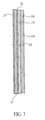
- FIG. 1 is a schematic cross-sectional view of a sheet of glass bearing a coating in accordance with the invention
- FIG. 2 is a schematic cross-sectional illustration of a multi-pane insulated glass unit incorporating a water-sheeting coating of the intervention;
- FIG. 3 is a schematic cross-sectional view of a laminated window structure of the type commonly used in automobile windshields bearing a water-sheeting coating of the invention
- FIG. 4 is a schematic illustration of a dual direction sputtering chamber for use in accordance with the intervention
- FIG. 5 is a schematic illustration of a multiple-zone dual direction sputtering chamber for use in accordance with another embodiment of the invention.
- FIG. 6 is an atomic force micrograph of a plain, uncoated surface of a sheet of conventional float glass
- FIG. 7 is a graph showing a height profile across a short length of the surface of the sheet of glass shown in FIG. 6;
- FIG. 8 is a atomic force micrograph of a surface of a sheet of float glass bearing a water-sheeting coating in accordance with the invention.
- FIG. 9 is a three-dimensional representation of an area of the same sheet of float glass illustrated in FIG. 8.
- FIG. 10 is a graph similar to FIG. 7, but showing a height profile across a short length of the surface of the water-sheeting coating shown in FIGS. 8 and 9 .
- FIG. 1 schematically illustrates a sheet of glass bearing a pair of coatings in accordance with one useful embodiment of the invention.
- the sheet of glass 10 includes an exterior face 12 and an interior face 14 .
- the designation of “interior” and “exterior” face in the ensuing discussion is somewhat arbitrary. It is assumed, though, that in most circumstances the exterior face will be exposed to an ambient environment wherein it may come into contact with dirt, water and the like.
- the interior face may also be oriented toward the same kind of ambient environment, as where a sheet of glass is used as a shower door. In such cases, it would be desirable to provide a water-sheeting coating of this invention on both the interior and exterior faces of the sheet of glass (not shown). In the embodiments illustrated in FIGS. 2 and 3, though, this “interior” face is actually protected and a second pane of glass stands between this interior face and the ambient environment.)
- the interior face 14 of the glass 10 bears a reflective coating 30 .
- this reflective coating may take any desired form depending on the desired properties. A wide variety of such films are known in the art and the precise nature of the reflective coating 30 will vary depending on the application for which the glass article is used. Several particularly useful and advantageous reflective coatings are discussed below, but others will be apparent to those in the field.
- the coating 30 may simply comprise a relative thick layer of a reflective metal. If so desired, a protective coating of a dielectric material may be applied over the surface of the metal opposite the surfacing contact with the glass. As is known in the art, this will help protect the metal layer from chemical and physical attack.
- a variety of mirror coatings known in the art which comprise a layer of a dielectric on either side of a reflective metal layer; many dichroic mirrors known in the art employ such a coating.
- the reflective coating 30 is typified as an infrared reflective coating of the type commonly used in low emissivity solar control films.
- such films will comprise a metal layer sandwiched between a pair of dielectric layers. This structure may be repeated to further enhance the infra-reflective properties of the film stack.
- One example of a useful infrared reflective film stack is disclosed in U.S. Pat. No. 5,302,449 (Eby, et al.), the teachings of which are incorporated herein by reference.
- the illustrative film stack 30 of FIG. 1 (referred to in Table 1 below as coating A) includes a base coat 32 which may comprise one or more layers of dielectric materials.
- this base coat 32 may comprise zinc oxide applied at a thickness of about 150-275 ⁇ .
- a first metal layer 34 may be applied directly on top of this base coat 32 .
- This metal may be, for example, silver applied at a thickness of between about 100 ⁇ and about 150 ⁇ .
- a second dielectric layer 38 may be applied over the first metal layer 34 . The thickness of this dielectric layer 38 will depend, at least in part, on whether a second metal layer 40 will be included in the film stack.
- this second dielectric layer 38 may typically comprise a relatively thick layer of a metal oxide, such as 700-750 ⁇ of zinc oxide.
- a relatively thin sacrificial layer 36 may be applied between the metal layer 34 and the dielectric layer 38 . This will help protect the metal layer 34 during the sputter deposition of the dielectric layer 38 .
- the sacrificial layer 36 may, for example, comprise a layer of titanium metal applied at a thickness of 25 ⁇ or less. This titanium metal will oxidize sacrificially (yielding an oxidized titanium denoted as “TiO x ” in Table 1) during the application of a metal oxide dielectric 38 , limiting any damage to underlying silver layer 34 .
- a second metal layer 40 is applied over the second dielectric layer 38 .
- the second metal layer 40 will usually be made of the same material as is the first metal layer 34 .
- this second metal layer 40 may comprise about 125-175 ⁇ of silver.
- a sacrificial layer 42 of titanium or the like may be applied over the metal layer 40 to protect the metal layer during subsequent deposition of the overlying dielectrics 44 and 46 .
- a third dielectric layer 44 is applied over the sacrificial layer 42 .
- This dielectric layer 44 can also be a metal oxide, e.g., zinc oxide applied at about 250-300 ⁇ .
- a protective overcoat 46 of another dielectric material can be applied over the dielectric layer 44 . In one preferred embodiment, this overcoat 46 may comprise a 50-60 ⁇ layer of Si 3 N 4 .
- Alternative film stacks may be preferred for different applications.
- various low emissivity film stacks may be applied to the interior face of the glass.
- Six, preferred low emissivity film stacks (identified as coatings B-G) will be described. These six film stacks are also summarized in Table 1 following their description below.
- Coating B comprises a layer of zinc oxide sputtered directly onto the interior face of the glass to a thickness of about 125 ⁇ . Silver is applied over this zinc oxide layer to a thickness of about 105 ⁇ . A thin coating of titania (applied as a sacrificial titanium layer which subsequently oxidizes, at least partially, as described above) is deposited over the silver layer to a thickness of about 25 ⁇ . A second zinc oxide layer is applied over the titania layer to a thickness of about 370 ⁇ . Finally, an outer coating of silicon nitride is sputtered onto the second zinc oxide layer to a thickness of about 60 Angstroms. This coating as reflective layer 30 in combination with a water-sheeting coating in accordance with the invention yields a particularly attractive product to meet consumer demands.
- the first three sputtered layers are the same as those of coating B (i.e., 125 ⁇ zinc oxide, 105 ⁇ silver, and 25 ⁇ titania).
- a second zinc oxide layer is sputtered onto the titania to a thickness of about 200 ⁇ .
- a silicon nitride layer is applied over this second zinc oxide layer to, a thickness of about 80 ⁇ .
- a third zinc oxide layer is then deposited over the silicon nitride layer to a thickness of about 105 ⁇ .
- a second layer of silicon nitride is sputtered onto the third zinc layer to a thickness of about 60 ⁇ .
- a third alternative film stack comprises a zinc oxide layer sputtered directly onto the interior face of the glass to a thickness of about 190 ⁇ . Silver is applied over this zinc oxide layer to a thickness of about 75 ⁇ . Next, a relatively thin layer of titania is applied to a thickness of about 25 ⁇ . Over this titania layer is applied a second layer of zinc oxide to a thickness of about 735 ⁇ . A second layer of silver is deposited over the second layer of zinc oxide to a thickness of about 135 ⁇ . A second thin layer of titania is then applied over the second layer of silver to a thickness of about 25 ⁇ . A third coating of zinc oxide is then applied over the second layer of titania to a thickness of about 200 ⁇ .
- an outer coating of silicon nitride is applied over the second layer of titania to a thickness of about 85 ⁇ .
- This coating as reflective layer 30 in connection with the water-sheeting coating of the present invention gives an outstanding product that has unique qualities that are highly useful to many consumers.
- the first three sputtered layers are the same as those of coating D (i.e., 190 ⁇ zinc oxide, 75 ⁇ silver, and 25 ⁇ titania).
- a second layer of zinc oxide is applied over the titania layer to a thickness of about 435 ⁇ .
- a silicon nitride layer is deposited over this second zinc oxide layer to a thickness of about 80 ⁇ .
- a third layer of zinc oxide is then deposited over the silicon nitride layer to a thickness of about 220 ⁇ .
- a second layer of silver is then applied over the third zinc oxide layer to a thickness of about 135 ⁇ .
- a second relatively thin layer of titania is applied over the second layer of silver to a thickness of about 25 ⁇ .
- a fourth layer of zinc oxide is then deposited over this second layer of titania to a thickness of about 200 ⁇ .
- an outer layer of silicon nitride is deposited over the fourth layer of zinc oxide to a thickness of about 85 ⁇ .
- a fifth alternative film stack comprises a layer of zinc oxide sputtered directly onto the interior face of the glass to a thickness of about 165 ⁇ . Over this zinc oxide layer is applied a silver layer to a thickness of about 110 ⁇ . Next, a relatively thin layer of titania is deposited over this silver layer to a thickness of about 25 ⁇ . A second zinc oxide layer is deposited over this titania layer to a thickness of about 745 ⁇ . A second silver layer is then applied over the second zinc oxide layer to a thickness of about 125 ⁇ . Over the second silver layer is applied a second relatively thin layer of titania to a thickness of about 25 ⁇ . A third zinc oxide layer is deposited onto this second titania layer to a thickness of about 280 ⁇ . Finally, an outer coating of silicon nitride is applied to a thickness of about 70 ⁇ . This coating as reflective layer 30 in combination with a water-sheeting coating of this invention produces a particularly useful and attractive product that meets the requirements of many consumers.
- the first three sputtered layers are the same as those of the film stack just discussed (i.e., 165 ⁇ zinc oxide, 110 ⁇ silver, and 25 ⁇ titania).
- a second layer of zinc oxide is then deposited over the titania layer to a thickness of about 445 ⁇ .
- Silicon nitride is then applied over the second zinc oxide layer to a thickness of about 80 ⁇ .
- a third layer of zinc oxide is then applied over this silicon nitride layer to a thickness of about 220 ⁇ .
- a second layer of silver is deposited onto the third zinc oxide layer to a thickness of 125 ⁇ . Over this second layer of silver is applied a second layer of titania to a thickness of about 25 ⁇ .
- a fourth zinc oxide layer is then deposited onto the second silver layer to a thickness of about 280 ⁇ .
- an outer coating of silicon nitride is applied over the fourth zinc oxide layer to a thickness of about 70 ⁇ .
- the water-sheeting coating 20 was applied to the inner surface 12 of the glass. It is preferred that this coating be applied directly on the surface of the glass sheet 12 .
- the glass which will typically be a soda/lime glass, is largely formed of silica and the water-sheeting coating is also desirably formed of silica, this is believed to provide a strong bond between these two layers and may enhance the water-sheeting performance of the coating 20 .
- the water-sheeting coating 20 of the invention desirably comprises silica deposited directly on the exterior surface 12 of the glass 10 .
- the exterior face 22 of this coating 20 is substantially non-porous but has an irregular surface. (This is schematically shown as a series of irregularly-spaced and -sized spikes on the exterior face 22 of the coating 31 ). Accordingly, attributing any specific thickness to this coating 20 will be inherently somewhat inaccurate.
- the coating 20 desirably has a median thickness of between about 15 ⁇ and about 350 ⁇ , with a range of between about 15 ⁇ and about 150 ⁇ being preferred. The major benefit of this coating at the least cost is believed to be evidenced at a range of about 20 ⁇ to about 120 ⁇ .
- This coating 20 may be applied to the exterior surface 12 of the glass 10 will be discussed in more detail below.
- FIG. 2 is a schematic illustration of a multi-pane insulated glass unit in accordance with a further embodiment of the invention.
- Insulated glass units are well known in the art and need not be discussed in any significant detail here. Briefly, though, such an insulated glass unit would generally comprise two panes of glass 10 , 100 held in a spaced-apart relationship by a spacer 110 to define a sealed interpane space 115 between the first pane 10 and the second pane 100 .
- the water-sheeting coating 20 carried by the exterior surface of the glass 10 is oriented away from the second pane of glass 100 while the reflective coating 30 carried by the interior face of the glass 10 is oriented toward the second pane of glass 100 .
- the second pane of glass 100 has an interior surface exposed to the interpane space 115 and an exterior surface oriented away from the first pane of glass 10 . If desired, a water-sheeting coating (not shown) may also be applied to the exterior surface 104 of the second pane of glass 100 . This would render the exterior and surfaces of both panes of glass resistant to staining and soiling.
- the spacer 110 is bonded on one side to the interior surface 102 of the second glass pane 100 and on the other side to the first glass pane 10 .
- the spacer may be bonded directly to the interior surface 14 of the glass 10 or the reflective coating 30 may extend out to the margins of the glass 10 and the spacer may be attached directly to that coating 30 .
- the spacer will be formed of metal or the like and will have a desiccant 112 retained therein. This desiccant will be allowed to communicate with the gas in the interpane space 115 to remove any moisture which may seep between the panes of glass.
- An exterior seal 114 may be carried around the external periphery of the spacer 110 to form a reliable gas and moisture barrier.
- FIG. 3 illustrates another application for a coated glass article of the invention.
- the glass sheet 10 is bonded to a second sheet of glass 100 by an intermediate tear-resistant plastic film 130 to form a laminated structure.
- this plastic layer 130 will take the form of a relatively thick layer of polyvinylbutyral or the like which is heat-fused to the other two sheets of glass.
- the coating 30 may be omitted.
- the reflective film 30 will comprise a heat-temperable infrared reflective film. A variety of such films are known in the art and the precise nature of this film is beyond the scope of the present invention, but any suitable heat-temperable coating 30 may be used.
- Laminated structures with an intermediate tear-resistant plastic film 130 may also be used as part of a shower door.
- Such shower doors may be more safe than plain glass doors, as the intermediate plastic film would tend to minimize glass shattering that might otherwise occur if the glass door were broken.
- the water-sheeting coating is desirably applied by sputtering, as are the low emissivity coatings or the reflective coating 30 , if present.
- These separate coatings can be applied using conventional sputtering equipment by applying the two coatings in separate passes through a sputtering line.
- the water-sheeting coating 20 of the invention can be applied to the exterior surface of the glass by positioning this surface of the glass beneath a silicon target in an oxidizing sputtering atmosphere.
- a multiple-layer reflective coating can be applied using a series of sputtering chambers in a conventional manner, with each chamber being adapted to sputter one or more specific layers of the desired film stack.
- a second water-sheeting coating can be sputtered directly onto the interior surface of the glass instead of such a reflective layer.
- One or both of the coated surfaces could then be exposed to periodic contact with water, whereby the water-sheeting coating would reduce soiling and staining of each exposed surface.
- FIG. 4 schematically illustrates a dual direction sputtering chamber in accordance with one embodiment of the present invention.
- Magnetron sputtering chambers are well known in the art and are commercially available from a variety of sources. While a thorough discussion of such magnetron sputtering chambers is beyond the scope of the present disclosure, one relatively useful structure for such a device is disclosed in U.S. Pat. No. 5,645,699 (Sieck), the teachings of which are incorporated herein by reference.
- magnetron sputtering involves providing a target formed of a metal or dielectric which is to be deposited on the substrate. This target is provided with a negative charge and a relatively positively charged anode is positioned adjacent the target. By introducing a relatively small amount of a desired gas into the chamber adjacent the target, a plasma of that gas can be established. Atoms in this plasma will collide with the target, knocking the target material off of the target and sputtering it onto the substrate to be coated. It is also known in the art to include a magnet behind the target to help shape the plasma and focus the plasma in an area adjacent the surface of the target.
- the sheet of glass 10 to be coated is positioned on a plurality of support rollers 210 which are spaced along the length of the sputtering chamber 200 . While the precise spacing of these rollers 210 can be varied, for reasons explained more fully below, it is desired that these rollers are spaced a little bit farther apart along at least a interim length of the chamber 200 to increase the effective coating area from the lower target 260 .
- the sheet of glass 10 is oriented to travel horizontally across these rollers, e.g., from left to right.
- the interior surface 14 of the glass is oriented upwardly while the exterior surface 12 of the glass is oriented downwardly to rest on the rollers 210 .
- the relative orientation of the glass within the sputtering chamber 200 can be switched so long as the relative positions of the upper targets 200 and the lower target 260 are also reversed.
- designating these targets as “upper” and “lower” targets is simply for purposes of convenience and the relative orientation of these elements within the sputtering chamber can easily be reversed if so desired.
- the sputtering chamber 200 shown in FIG. 4 includes two spaced-apart upper sputtering targets 220 a and 220 b. While these targets can be planar targets, they are illustrated as being so-called rotary or cylindrical targets. These targets are arranged generally parallel to one another with a plurality of anodes 230 extending horizontally and generally parallel to these targets. As suggested in U.S. Pat. No. 5,645,699, an intermediate anode 230 may also be positioned between these two targets.
- a gas distribution system is used to supply the sputtering gas to the chamber adjacent the targets 220 a and 220 b . While a variety of gas distribution systems are known in the art, this distribution system may simply comprise a pair of pipes 235 with a plurality of spaced-apart openings or nozzles oriented generally toward the target.
- the use of multiple targets positioned above a glass substrate in a magnetron sputtering chamber is fairly conventional in the field.
- the unique aspect of the sputtering chamber 200 FIG. 4, though, is the presence of the “lower” target 260 .
- This target is the target used to sputter the water-sheeting coating 20 of the invention directly on the exterior surface 12 of the glass.
- the lower target 260 is provided with at least one, and preferably two, anodes 270 in sufficient proximity to establish a stable plasma.
- the gas distribution pipes 235 shown adjacent the upper targets 220 a and 220 b are undesirably far from the lower target 260 and the intermittent presence of the glass 10 will effectively divide the sputtering chamber 200 into two separate functional areas. Accordingly, it is preferred to have separate gas distribution pipes 275 positioned beneath the gas adjacent the lower target 260 to ensure a consistent supply of gas for the plasma adjacent the target. If so desired, the lower pipes 275 and the upper pipes 235 may be a part of the same gas distribution system, i.e., both sets of pipes can be connected to a single gas supply.
- the nature of the gas supplied by the lower pipes 275 will depend at least in part on the nature of the sputtering target 260 .
- the target In conventional magnetron sputtering, the target must serve as a cathode. Due to the dielectric nature of SiO 2 , it can be exceedingly difficult to reliably sputter using a silica target. As a consequence, it is preferred that the target comprise silicon metal rather than silica.
- the material actually deposited on the exterior surface 12 of the glass can be converted to silica by including oxygen in the gas supplied through the lower gas distribution pipes 275 .
- the successive sheets of glass 10 will effectively divide the sputtering chamber, this does not preclude gas introduced in one area of the chamber from travelling elsewhere in the chamber.
- the lower target 260 comprise silicon metal sputtered in an oxidizing atmosphere, it is important that the sputtering of the upper targets 220 a and 220 b not be adversely affected by the presence of any excess oxygen which may be introduced through the lower pipes 275 . This may effectively preclude the use of this dual direction sputtering chamber 200 to deposit a water-sheeting coating 20 on one side of the glass sheet and an oxygen-sensitive metal on the other surface. More advantageously, the dual direction sputtering chamber of FIG.
- the sputtered dielectric may be a nitride or the like so long as the introduction of some metal oxide into the nitride being deposited will not adversely affect the coating being applied.
- the dielectric being applied to the interior surface 14 is an oxide (or at least a partial oxide) so that any commingling of the gases introduced through the two sets of pipes 235 and 275 will not adversely affect either the dielectric layer or the water-sheeting coating.
- one or both of the targets 220 a and 220 b may be made of titanium metal or TiO x (where 1 ⁇ X ⁇ 2) and the gas introduced through both sets of gas distribution pipes 235 and 275 may comprise an appropriately balanced mixture of argon and oxygen.
- the upper and lower targets in a sputtering chamber are both adapted to sputter water-sheeting coatings onto the sheet of glass.
- both targets may comprise silicon and may be sputtered in an oxidizing atmosphere.
- the upper and lower targets can be sputtered simultaneously to deposit silica on the interior and exterior surfaces of the glass at the same time.
- the spacing of the rollers 210 used to support the glass is kept fairly small to permit smaller glass substrates to be processed on the line without any significant risk of having the glass fall between the rollers.
- this spacing may be increased.
- the maximum safe spacing will need to be determined on a case-by-case basis for a given range of anticipated glass sizes.
- rollers in other areas of the sputtering apparatus can be maintained at their normal spacing. It may be desirable to make a few of the rollers in the dual direction sputtering chamber 200 easily removed so the chamber can be converted from the illustrated configuration to a more conventionally operated chamber coating only one side of the glass and having rollers spaced more closely together.
- rollers could instead be made smaller in diameter.
- Conventional rollers are hollow metal tubes. If so desired, the smaller diameter rollers can be stiffened, e.g., by filling them with a rigid foam. In order to maintain the same transport speed of the glass along the support, these smaller-diameter rollers would have to be turned more rapidly, e.g., by means of a pair of gears having the desired gear ratio.
- the rollers 210 can be of any conventional structure. It has been found that good results can be obtained by employing cylindrical aluminum rollers about which a rope of KevlarTM is spirally wound, with the KevlarTM providing the surface with which the glass is in direct contact.
- a sputtering line comprising a series of sputtering chambers.
- Each sputtering chamber includes a plurality of rollers that define a continuous substrate support. At least one of these chambers is an upward sputtering chamber that includes a lower target positioned below the rollers in that chamber.
- a sheet of glass with a clean interior surface and a clean exterior surface is provided. The sheet is positioned in the upward sputtering chamber such that the exterior surface of the sheet of glass rests on one or more of the rollers in that chamber.
- the lower target is then sputtered to deposit silica directly onto the exterior surface of the glass.
- the sputtered silica is discharged from the lower target and travels between the rollers in the upward sputtering chamber before being deposited on the glass. This yields a water-sheeting coating having a contact angle with water below about 25° which causes water applied to the exterior surface to sheet.
- the dual direction sputtering chamber 200 of FIG. 4 may be sufficient to apply the entire desired coating to both the interior and exterior surfaces of the glass. More often, though, the sputtering chamber 200 would be part of a sputtering line comprising a series of sputtering chambers. Each sputtering chamber in the line could include both an upper target and a lower target, but in most conventional applications the film stack applied to the upper surface of the glass will be more complex (i.e. will comprise a series of distinct layers of varying composition) and thicker than is the water-sheeting coating of the invention. As a consequence, a majority of the sputtering chambers can comprise conventional, downward sputtering chambers having only an upper target, with no target positioned beneath the supports.
- the sputtering line comprises a combination of downward sputtering chambers and dual direction sputtering chambers 200
- the position of the dual direction chambers along the sputtering line can be varied.
- the water-sheeting coating of the invention is applied by sputtering a silicon-containing target (e.g., one formed primarily of silicon or formed of silicon doped with aluminum) in an oxidizing atmosphere, one should not attempt to deposit an oxidizable metal layer (e.g., an infrared reflective silver layer of the type conventionally used in low emissivity film stacks) on the upper surface of the glass in the same chamber.
- a silicon-containing target e.g., one formed primarily of silicon or formed of silicon doped with aluminum
- an oxidizable metal layer e.g., an infrared reflective silver layer of the type conventionally used in low emissivity film stacks
- At least those chambers used to sputter a metal layer may be operated as a downward sputtering chamber by omitting the lower target. It would be possible, though, to deposit a metal oxide (e.g., SiO 2 , ZnO or SnO 2 ) on the upper surface of the glass in the same chamber.
- a metal oxide e.g., SiO 2 , ZnO or SnO 2
- the water-sheeting coating of the invention be applied in the first sputtering chamber or, if necessary, the first several sputtering chambers to make sure that the water-sheeting coating is applied before the glass surface is damaged or soiled by contact with the rollers supporting the glass within the chambers. Quite surprisingly, it has been found that the opposite is true—the water-sheeting coating of the invention is optimally applied in the last sputtering chamber. If more than one dual direction sputtering chamber 200 is necessary to deposit a sufficiently thick water-sheeting coating without unduly slowing down glass speed through the sputtering line, the water-sheeting coating is optimally applied in the last few sputtering chambers.
- the water-sheeting coating of the invention is applied at the beginning of the sputtering line, the majority of the exterior surface of the glass will exhibit the desired water-sheeting properties. However, the margins of the glass may not exhibit these improved properties on a consistent basis. This is believed to be due to a slight overspray of the coating applied to the upper surface of the glass after deposition of the water-sheeting coating, wherein a very small amount of the material being applied to the upper surface will drift down to the lower surface and overlie the water-sheeting coating adjacent the edges of the glass sheet. While this oversprayed coating is thin enough as to have no readily discernable effect on the optical properties of the glass, this virtually invisible coating compromised the benefits of the water-sheeting coating around the edges of the glass.
- a dual direction sputtering chamber 200 such as that shown in FIG. 4 is believed to minimize the cost and maximize production efficiency in applying coatings to both sides of the sheet of glass.
- a water-sheeting coating of the invention could be applied in one pass while the reflective coating is applied to the other side of the glass in a second pass, flipping the glass between the passes to permit all of the targets to be positioned on the same side of the supports in the chamber(s). This is much less efficient than the process outlined above, though, and is not believed to be suitable for low-cost commercial glass production.
- the sputtering chamber 200 of FIG. 4 is ideal if the upper targets 220 a , 220 b and the lower target 260 have substantially the same composition. If the upper targets have a different composition from the lower target, though, the cross-contamination of the different targets can lead to problems in sputtering or in maintaining consistent product quality.
- this problem may be overcome by independently controlling the power supplied to each of the sputtering targets to ensure that each target is sputtering only when the glass is positioned to shield the upper and lower targets from one another.
- Current commercially available power supply controllers are not configured in this fashion, however.
- the control logic for such an arrangement can be unduly difficult if the sputtering line is used to coat glass substrates of varying sizes rather than a consistent size.
- FIG. 5 illustrates one possible sputtering chamber 300 which can be used to coat both the interior surface 14 and the exterior surface 12 of the substrate in a single pass without significant cross contamination of the sputtering targets.
- Elements serving an, analogous function to elements shown in FIG. 4 bear like reference numbers, but indexed by 100 , e.g., the upper gas distribution pipes 335 of FIG. 5 are functionally analogous to the upper gas distribution pipes 235 of FIG. 4 .
- the sputtering chamber 300 of FIG. 5 is effectively divided into three coating zones 300 a , 300 b and 300 c by a pair of barriers 340 . Some fraction of the gas in one coating zone may flow into another coating zone, so it is best to use a similar atmosphere in all three zones. However, the barriers 340 serve to effectively limit the amount of material sputtered in one coating zone which lands on a target in another coating zone.
- each of the three coating zones 300 a - 300 c is adapted to hold up to four targets, with two targets positioned above the substrate and two positioned below the substrate.
- FIG. 5 schematically illustrates each of the upper target mounts 321 - 326 vertically aligned with one of the lower target mounts 361 - 366 , respectively. It should be understood, however, that the targets need not be vertically aligned in this fashion and may be more advantageously positioned in a horizontally staggered arrangement.
- the first coating zone 300 a has two upper targets ( 320 a and 320 b ), but no lower targets on the lower target mounts 361 or 362 . While a sputtering gas should be supplied to the upper gas distribution pipes 335 and power should be supplied to the upper anodes 330 in the first coating zone, there is no need to deliver any gas to the lower gas distribution pipes 375 or any power to the lower anodes 370 .
- the second coating zone 300 b has two lower targets 360 c and 360 d, but neither of the upper target mounts 323 and 324 carry sputtering targets.
- the third coating zone 300 c has two lower targets 360 e and 360 f, but neither of the upper target mounts 325 and 326 carry sputtering targets.
- the first coating zone 300 a is used to apply the outermost layer of the reflective film stack carried by the interior surface 14 of the substrates while the last two coating zones 300 b and 300 c are used to sputter the water-sheeting coating 20 on the exterior surface 12 of the substrates.
- the arrangement of targets in the multiple-zone sputtering chamber 300 of FIG. 5 is merely illustrative and it should be understood that the target arrangement can be varied to maximize production efficiency for different products.
- a silicon-containing target can be mounted on each of the lower target mounts 361 - 366 while none of the upper target mounts 321 - 326 carry a target.
- a thinner coating will suffice (or if glass speed through the coating chamber is suitably reduced)
- only the last two lower target mounts 325 and 326 can be provided with targets while each of the first four upper target mounts 321 - 324 carry sputtering targets.
- any one or more of the coating zones 300 a - 300 c can be operated much like the dual-direction sputtering chamber 200 of FIG. 4 by mounting targets in the upper and lower target mounts of the same zone.
- FIGS. 4 and 5 The apparatus of FIGS. 4 and 5 and the method of depositing coatings using such coating systems is discussed in the present application primarily in the context of applying a reflective film stack on one side of the glass and a water-sheeting coating on the other side of the glass. It is to be understood, however, that this apparatus and method can be used to apply coatings to both sides of a pane of glass regardless of the nature of the coatings applied thereto.
- the apparatus can be used to apply an anti-reflective coating on both sides of a pane of glass, to apply infrared reflective coatings to both sides of a transparent or translucent organic substrate, or to apply a water-sheeting coating to each side of the same substrate.
- a substrate can be provided with a sputtered coating (regardless of composition) on both sides in a single pass through the coating apparatus while the glass is maintained in a constant orientation, i.e. wherein it does not need to be flipped, turned or otherwise manipulated.
- This enables the use of a simple set of standard transport rollers to move the glass along the production line.
- a layer of SiO 2 in accordance with the invention may be sputter deposited using a silicon dioxide target in an inert atmosphere, but silica is a poor conductor and it can be difficult to sputter such dielectric materials in a DC sputtering apparatus.
- a target comprising silicon with about 5% aluminum be sputtered in an oxidizing atmosphere.
- the atmosphere in the sputtering chamber can be varied to achieve the optimum sputtering rate. While the sputtering atmosphere should be oxidizing, it need not be pure oxygen. To the contrary, a mixture of oxygen and an inert gas will enhance the sputtering rate. It is believed that a sputtering gas comprising oxygen and up to about 40% argon (preferably 0-20% argon) maintained at about 3 ⁇ 10 ⁇ 3 mbar will suffice.
- the power applied to the sputtering target should be optimized to reduce arcing yet maximize sputtering rate. A power of up to about 80 kW should yield acceptable results.
- One manufacturing arrangement which has been found to work well utilizes three rotary sputtering targets of silicon doped with about 5% aluminum, with a power of about 42 kW being applied to each target.
- the atmosphere in the sputtering chamber comprises 100% O 2 at a pressure of about 2.5-4.5 mTorr.
- the glass substrate is moved past these sputtering targets at about 225-500 inches per minute.
- molten glass is floated on a bath of molten tin and the glass is referred to as having an upper side and a lower, or “tin” side.
- tin lower, or “tin” side.
- the coating is applied to the upper side of the glass due to some minor surface imperfections in the tin side of the glass which can arise due to contact with support rollers in the annealing lehr.
- a sheet of float glass 10 is to be provided with both a water-sheeting coating 20 and a reflective layer 30 , it is preferred that the upper surface of the sheet glass be used as the interior surface 14 of the glass to receive the reflective coating 30 while the tin side of the glass is used as the exterior surface to receive the water-sheeting coating 20 .
- FIG. 6 is an atomic force micrograph of one square micron ( ⁇ m) of the surface of the tin side of an untreated sheet of float glass.
- FIG. 7 is a graph representing a profile of the same side of the sheet of glass along about a 1 ⁇ m line on that surface. Both of these images were obtained by atomic force microscopy using a Digital Instruments Nanoscope III using a standard silicon tip.
- FIGS. 6 and 7 illustrate a relatively smooth surface. While this surface is not perfectly smooth and it appears to have a slightly rough appearance in FIG. 6, it is important to note that the scale of these images is quite small.
- two peaks in the profile of FIG. 7 are highlighted by a pair of arrows.
- the two darker arrows toward the left in FIG. 7 (at about 0.25 ⁇ m along the abscissa) mark the beginning and the apex of a first peak A; the two lighter arrows toward the right in FIG. 7 (at about 0.9 ⁇ m along the abscissa) mark the apex and end of a second peak B.
- the first peak A is less than 0.7 nm in height while the second, taller peak B is only about 1.7 nm tall.
- FIGS. 8-10 are analogous representations of a sheet of float glass on the tin side of which a water-sheeting coating of the invention has been applied.
- FIG. 8 is a micrograph much like FIG. 6, also representing 1 ⁇ m 2 of the surface.
- FIG. 10 is a graph much like FIG. 7, but wherein the ordinate axis represents a range of 20 nm rather than the smaller 5 nm range of FIG. 7 .
- FIG. 9 is a perspective view which highlights the surface features of the water-sheeting coating.
- the smaller vertical bar to the right of the primary image is a legend representing the gray scale associated with different heights from the base surface.
- FIGS. 9 and 10 give a better indication of the height and shapes of these projections.
- the two darker arrows highlight the apex and end of one peak A while the two lighter arrows point to the apex and end of a second peak B.
- the second, smaller peak B in FIG. 10 is about 4.3 nm tall while the first peak A is nearly 10 nm tall. This is over five times as tall as the peaks illustrated in FIG. 7 .
- FIGS. 8-10 the surface of the coating shown in FIGS. 8-10 is uneven, but appears to be relatively non-porous. This is in sharp contrast to the photomicrographs in Takamatsu et al.'s U.S. Pat. No. 5,394,269, which show a porous sol gel-derived coating having pores on the order of 50-200 nm penetrating the coating.
- FIGS. 6-10 are representative of their respective surfaces. As a matter of fact, it is acknowledged that these images could be atypical of the overall surfaces of the samples in question, so it may not be appropriate to attach too much significance to the apparent differences in the surface structure of these two glasses.
- the surface of the water-sheeting coating 20 of the invention is relatively non-porous and differs from an untreated float glass surface in that it is significantly more uneven and irregular, having a number of discrete, spaced-apart peaks rising significantly above the rest of the surface.
- the behavior of a sheet of glass coated with a water-sheeting coating of the invention is visibly different from that of a similar sheet of glass not bearing the present coating.
- a glass surface bearing a water-sheeting coating 20 tends to sheet water more readily and is noticeably easier to clean without any visible streaks or defects than is a comparable sheet of glass under the same conditions.
- a comparative sample was prepared.
- a plain, untreated pane of glass was thoroughly cleaned and laid horizontally on a set of rollers.
- a small, square piece of glass was laid on the upper surface of the pane of glass to serve as a template covering part of the surface of the pane.
- the pane and overlying template were passed into a magnetron sputtering chamber and a coating of about 35 ⁇ of SiO 2 was deposited.
- the template was then removed, leaving a pane of glass with a water-sheeting coating 20 of the invention over most of its surface, but having an uncoated area which was beneath the template during the sputtering operation.
- the opposite side of the glass i.e., the side of the glass facing away from the side provided with the SiO 2 coating, was coated with a low emissivity, infrared-reflective film stack having two silver layers spaced apart from one another and from the glass using a plurality of dielectric layers.
- the partially coated surface of the glass pane was visibly inspected. When completely clean, the boundaries of the uncoated area which underlied the template during sputtering was essentially undetectable to the unaided eye, indicating that the water-sheeting coating had a minimal impact on the basic optical properties of the glass.
- a fine spray of atomized water droplets was sprayed on the surface using a simple, hand-operated spray bottle of the type conventionally used to spray household cleaning products. Once the spray was applied, the boundaries of the uncoated area were readily visible. The water on the area bearing the coating 20 sheeted to an apparently uniform film of water, but the area without the coating had a less uniform appearance.
- a conventional cleaning solution commercially available under the trademark Windex® was sprayed on the surface of the glass pane and the surface was wiped with a paper towel until the area bearing the coating 20 appeared dry and no longer showed any visible streaks. When wiping ceased, the uncoated area still had visible streaks of moisture. While these visible streaks on the uncoated area eventually dried without leaving any substantial residual streaking on the glass, it is believed that the average person would tend to continue to wipe this area until all visible streaks disappeared, meaning that the person would expend less time and effort cleaning a glass article bearing a water-sheeting coating 20 than a glass article without such a coating.
- Both of the samples were subjected to a salt spray test in accordance with ASTM B117 using a 5% salt solution for 250 hours. Briefly, the samples were cleaned and placed in a Singleton SCCH #20 Corrosion Cabinet at an angle of about 15-30° from vertical, with Sample B being oriented such that the surface bearing the water-sheeting coating 20 was oriented to face downwardly.
- a 5% salt solution (5 wt % sodium chloride, 95 wt % distilled water) was atomized in the cabinet at about 35° C. for 250 hours, with the salt solution being collected at a rate of about 1.8 ml per 80 cm per hour in the collection cylinders in the cabinet. Thereafter, the samples were removed from the cabinet, rinsed, allowed to dry and visually inspected. Sample A had more numerous water spots than did Sample B and the water spots on Sample A were more visible than the light streaks on Sample B.
- the contact angle of the water on the surface of the glass sheet was then measured using a commercially available measuring device, with the contact angle for Sample B being measured on the surface bearing the coating 20 .
- the contact angle for Sample A was about 32 degrees; the contact angle for Sample B was about 12 degrees.
- each sample was first dipped in a beaker of boiling tap water maintained at about 100° C. and held there for about 5 seconds, after which it was deposited in a beaker of ice water maintained at about 0° C. and held there for about 5 seconds. This process was repeated 25 times.
- the samples were then placed in a Singleton Model SL23 humidity test chamber maintained at about 90% relative humidity at about 120° F. (about 49° C.) for about 500 hours. Each sample was then visually inspected. As in Experimental Example 1, it was determined that Sample A exhibited more numerous and more visible water spots than did Sample B.
- Examples A1 and A2 Two samples of uncoated glass (Samples A1 and A2) and two samples of coated glass (Samples B1 and B2) were cleaned and their haze measurements were taken. Each of the uncoated samples had haze measurements of about 0.09% while the haze measurement for the glass with a water-sheeting coating 20 was about 0.08%.
- a cement mixture was prepared by mixing 4 ounces (about 11.5 g) of portland cement to 1000 ml of water. Two samples of uncoated glass (Samples A1 and A2) and two samples of coated glass (Samples B1 and B2) were held in this solution for about ten minutes then removed. Samples A1 and B1 were then rinsed liberally with water (but without any rubbing) and allowed to dry; Samples A2 and B2 were allowed to air dry without rinsing.
- haze and contact angle measurements were made. After the cement treatment, the haze for Samples A1 and B1 remained unchanged at 0.09% and 0.08%, respectively. The haze measurement for Sample B2 likewise remained unchanged at about 0.08%, but the haze measurement for Sample A2 increased slightly from about 0.09% to about 0.10%.
- the contact angle for Samples A1 and A2 were measured prior to the cement treatment at about 26°; Samples B1 and B2 had contact angles of about 11° at the same stage. After the cement treatment, the contact angle for Sample A1 was about 32° while the contact angle for Sample B1, the other rinsed sample, was about 10°. The contact angle for Sample A2 was about 33° while the contact angle for Sample B2, the other air dried sample, was about 14°.
- a set of these samples were subjected to an accelerated weathering test and the contact angle and ease of cleaning was checked on a periodic basis.
- the samples were placed in a stainless steel enclosure maintained at a temperature of about 160° F. (about 71° C.).
- a 300 W ultraviolet light source (sold by Osram under the trade name Ultra-Vitalux) was positioned toward the bottom of the enclosure and samples were positioned at an angle of about 45° with respect to horizontal with the bottom edges of the sample spaced about 10 inches (about 25 cm) from the bulb.
- the samples were removed from the enclosure and the contact angle was measured in much the same manner as that outlined above.
- the contact angles were as follows:
- a water-sheeting coating 20 of the invention makes the glass surface significantly easier to clean than either the standard, uncoated glass or glass coated with any one of several commercially available coatings designed to make glass easier to clean.
- these commercially available coatings actually made the glass seem more difficult to clean.
- the “ease of cleaning” standards employed in this Experimental Example are fairly representative of how an average home owner would perceive ease of cleaning. For example, even if streaks of the cleaning fluid on the pane of glass might dry without leaving any permanent streaks, an average person is likely to keep wiping the area until the glass appears clean to avoid any residual streaking.
Landscapes
- Chemical & Material Sciences (AREA)
- Organic Chemistry (AREA)
- Engineering & Computer Science (AREA)
- Materials Engineering (AREA)
- Chemical Kinetics & Catalysis (AREA)
- Life Sciences & Earth Sciences (AREA)
- General Chemical & Material Sciences (AREA)
- Geochemistry & Mineralogy (AREA)
- Mechanical Engineering (AREA)
- Metallurgy (AREA)
- Surface Treatment Of Glass (AREA)
- Joining Of Glass To Other Materials (AREA)
- Physical Vapour Deposition (AREA)
Priority Applications (9)
| Application Number | Priority Date | Filing Date | Title |
|---|---|---|---|
| US09/599,301 US6660365B1 (en) | 1998-12-21 | 2000-06-21 | Soil-resistant coating for glass surfaces |
| CA2413355A CA2413355C (en) | 2000-06-21 | 2001-06-19 | Soil-resistant coating for glass surfaces |
| AU2001268543A AU2001268543A1 (en) | 2000-06-21 | 2001-06-19 | Soil-resistant coating for glass surfaces |
| EP01946499.9A EP1292546B1 (en) | 2000-06-21 | 2001-06-19 | Soil-resistant coating for glass surfaces |
| MXPA02012802A MXPA02012802A (es) | 2000-06-21 | 2001-06-19 | Recubrimientos resistentes a la suciedad para superficies de vidrio. |
| JP2002505316A JP2004501852A (ja) | 2000-06-21 | 2001-06-19 | ガラス表面用の防汚被覆 |
| PCT/US2001/019500 WO2002000564A1 (en) | 2000-06-21 | 2001-06-19 | Soil-resistant coating for glass surfaces |
| NO20026139A NO20026139L (no) | 2000-06-21 | 2002-12-19 | Smuss-motstandig belegg for glassoverflater |
| US10/464,528 US6939446B2 (en) | 1998-12-21 | 2003-06-17 | Soil-resistant coating for glass surfaces |
Applications Claiming Priority (4)
| Application Number | Priority Date | Filing Date | Title |
|---|---|---|---|
| US11325998P | 1998-12-21 | 1998-12-21 | |
| PCT/US1999/002208 WO2000037377A1 (en) | 1998-12-21 | 1999-02-02 | Soil-resistant coating for glass surfaces |
| US16849799P | 1999-12-02 | 1999-12-02 | |
| US09/599,301 US6660365B1 (en) | 1998-12-21 | 2000-06-21 | Soil-resistant coating for glass surfaces |
Related Parent Applications (2)
| Application Number | Title | Priority Date | Filing Date |
|---|---|---|---|
| US09/020,299 Division US6090381A (en) | 1997-02-11 | 1998-02-06 | Stimulation of an immune response with antibodies labeled with the . .alpha-galactosyl epitope |
| PCT/US1999/002208 Continuation-In-Part WO2000037377A1 (en) | 1998-12-21 | 1999-02-02 | Soil-resistant coating for glass surfaces |
Related Child Applications (2)
| Application Number | Title | Priority Date | Filing Date |
|---|---|---|---|
| US10/114,315 Division US20020176856A1 (en) | 1997-02-11 | 2002-04-03 | Stimulation of an immune response with antibodies labeled with the alpha-galactosyl epitope |
| US10/464,528 Continuation US6939446B2 (en) | 1998-12-21 | 2003-06-17 | Soil-resistant coating for glass surfaces |
Publications (1)
| Publication Number | Publication Date |
|---|---|
| US6660365B1 true US6660365B1 (en) | 2003-12-09 |
Family
ID=24399072
Family Applications (2)
| Application Number | Title | Priority Date | Filing Date |
|---|---|---|---|
| US09/599,301 Expired - Lifetime US6660365B1 (en) | 1998-12-21 | 2000-06-21 | Soil-resistant coating for glass surfaces |
| US10/464,528 Expired - Lifetime US6939446B2 (en) | 1998-12-21 | 2003-06-17 | Soil-resistant coating for glass surfaces |
Family Applications After (1)
| Application Number | Title | Priority Date | Filing Date |
|---|---|---|---|
| US10/464,528 Expired - Lifetime US6939446B2 (en) | 1998-12-21 | 2003-06-17 | Soil-resistant coating for glass surfaces |
Country Status (8)
| Country | Link |
|---|---|
| US (2) | US6660365B1 (no) |
| EP (1) | EP1292546B1 (no) |
| JP (1) | JP2004501852A (no) |
| AU (1) | AU2001268543A1 (no) |
| CA (1) | CA2413355C (no) |
| MX (1) | MXPA02012802A (no) |
| NO (1) | NO20026139L (no) |
| WO (1) | WO2002000564A1 (no) |
Cited By (27)
| Publication number | Priority date | Publication date | Assignee | Title |
|---|---|---|---|---|
| US20030059623A1 (en) * | 2000-09-11 | 2003-03-27 | O'shaughnessy Roger D | Temporary protective covers |
| US20030118860A1 (en) * | 2001-09-11 | 2003-06-26 | O'shaughnessy Roger D. | Hydrophilic surfaces carrying temporary protective covers |
| US20040175511A1 (en) * | 2002-12-31 | 2004-09-09 | Klaus Hartig | Coater having substrate cleaning device and coating deposition methods employing such coater |
| US20060014027A1 (en) * | 2004-07-14 | 2006-01-19 | Afg Industries, Inc. | Silicon oxycarbide coatings having durable hydrophilic properties |
| US20060033867A1 (en) * | 2004-08-10 | 2006-02-16 | Krisko Annette J | LCD mirror system and method |
| US20060096614A1 (en) * | 2004-11-08 | 2006-05-11 | Krisko Annette J | Surface treating methods, compositions and articles |
| US20060105103A1 (en) * | 2004-11-15 | 2006-05-18 | Klaus Hartig | Methods and equipment for depositing coatings having sequenced structures |
| WO2007044814A1 (en) | 2005-10-11 | 2007-04-19 | Cardinal Cg Company | Methods and equipment for depositing high quality reflective coatings |
| US20070125304A1 (en) * | 2005-12-01 | 2007-06-07 | Cardinal Cg Company | Transport rollers |
| US20080026147A1 (en) * | 2006-07-28 | 2008-01-31 | Gulbrandsen Chemicals, Inc. | Method and formulation for depositing a metal-containing coating on a substrate |
| US20080152804A1 (en) * | 2006-07-28 | 2008-06-26 | Gulbrandsen Chemicals, Inc. | Method for depositing a metal-containing coating on a substrate |
| US7713632B2 (en) | 2004-07-12 | 2010-05-11 | Cardinal Cg Company | Low-maintenance coatings |
| US20100221575A1 (en) * | 2008-11-04 | 2010-09-02 | Randy Leland Stull | Coated glass surfaces and method for coating a glass substrate |
| US20100288625A1 (en) * | 2007-02-28 | 2010-11-18 | Ulvac, Inc. | Film deposition apparatus and film deposition method |
| US7923114B2 (en) | 2004-12-03 | 2011-04-12 | Cardinal Cg Company | Hydrophilic coatings, methods for depositing hydrophilic coatings, and improved deposition technology for thin films |
| US7989094B2 (en) | 2006-04-19 | 2011-08-02 | Cardinal Cg Company | Opposed functional coatings having comparable single surface reflectances |
| US8092660B2 (en) | 2004-12-03 | 2012-01-10 | Cardinal Cg Company | Methods and equipment for depositing hydrophilic coatings, and deposition technologies for thin films |
| US8506768B2 (en) | 2007-09-14 | 2013-08-13 | Cardinal Cg Company | Low-maintenance coatings, and methods for producing low-maintenance coatings |
| JP2014520966A (ja) * | 2011-07-21 | 2014-08-25 | フラオンホファー−ゲゼルシャフト・ツア・フェルデルング・デア・アンゲヴァンテン・フォルシュング・エー・ファオ | 基板上に少粒子層を形成するための方法および装置 |
| US9738967B2 (en) | 2006-07-12 | 2017-08-22 | Cardinal Cg Company | Sputtering apparatus including target mounting and control |
| US9748082B2 (en) | 2012-08-24 | 2017-08-29 | Cardinal Cg Company | Apparatus for cylindrical magnetron sputtering |
| US9812296B2 (en) | 2015-02-03 | 2017-11-07 | Cardinal Cg Company | Sputtering apparatus including gas distribution system |
| US10273573B2 (en) | 2015-12-11 | 2019-04-30 | Cardinal Cg Company | Method of coating both sides of a substrate using a sacrificial coating |
| US10513459B2 (en) | 2017-05-04 | 2019-12-24 | Apogee Enterprises, Inc. | Low emissivity coatings, glass surfaces including the same, and methods for making the same |
| US10578782B2 (en) | 2016-04-19 | 2020-03-03 | Apogee Enterprises, Inc. | Coated glass surfaces and method for coating a glass substrate |
| US10604442B2 (en) | 2016-11-17 | 2020-03-31 | Cardinal Cg Company | Static-dissipative coating technology |
| US10816703B2 (en) | 2015-09-28 | 2020-10-27 | Tru Vue, Inc. | Near infrared reflective coatings |
Families Citing this family (6)
| Publication number | Priority date | Publication date | Assignee | Title |
|---|---|---|---|---|
| US20040071889A1 (en) * | 2002-08-07 | 2004-04-15 | Hoya Corporation | Method of producing an antireflection-coated substrate |
| FR2857958B1 (fr) * | 2003-07-25 | 2005-12-23 | Saint Gobain | Substrat traite contre l'irisation |
| DE102004032635A1 (de) * | 2004-07-06 | 2006-02-09 | Gfe Metalle Und Materialien Gmbh | Verfahren zur Herstellung eines Titan-Suboxid-basierten Beschichtungswerkstoff, entsprechend hergestellter Beschichtungswerkstoff und damit versehenes Sputtertarget |
| PL2027076T3 (pl) * | 2006-05-31 | 2012-10-31 | Agc Glass Europe | Oszklenie o niskiej emisyjności |
| WO2009115424A1 (en) * | 2008-03-17 | 2009-09-24 | Nv Bekaert Sa | A light weight electrochromic mirror stack |
| KR101308040B1 (ko) * | 2013-07-09 | 2013-09-12 | (주)노루페인트 | 내 오염성을 갖는 에너지 절감형 유리 코팅 조성물 및 이를 적용한 에너지 절감형 유리 구조물 |
Citations (131)
| Publication number | Priority date | Publication date | Assignee | Title |
|---|---|---|---|---|
| US2780553A (en) | 1955-07-07 | 1957-02-05 | Ohio Commw Eng Co | Process of providing a controlled atmosphere containing a heat decomposable metal compound |
| US2808351A (en) | 1952-10-31 | 1957-10-01 | Libbey Owens Ford Glass Co | Electrically conducting coated glass or ceramic articles suitable for use as a lens, a window or a windshield, or the like |
| US3505092A (en) | 1968-06-14 | 1970-04-07 | Libbey Owens Ford Co | Method for producing filmed articles |
| US3528906A (en) | 1967-06-05 | 1970-09-15 | Texas Instruments Inc | Rf sputtering method and system |
| US3840451A (en) | 1971-10-28 | 1974-10-08 | V Golyanov | Method of producing an artificial diamond film |
| US3844924A (en) | 1970-08-03 | 1974-10-29 | Texas Instruments Inc | Sputtering apparatus for forming ohmic contacts for semiconductor devices |
| US3852098A (en) | 1972-12-15 | 1974-12-03 | Ppg Industries Inc | Method for increasing rate of coating using vaporized reactants |
| US3925182A (en) | 1973-09-25 | 1975-12-09 | Shatterproof Glass Corp | Method for continuous production of sputter-coated glass products |
| US3968018A (en) | 1969-09-29 | 1976-07-06 | Warner-Lambert Company | Sputter coating method |
| US3970037A (en) | 1972-12-15 | 1976-07-20 | Ppg Industries, Inc. | Coating composition vaporizer |
| US3990784A (en) | 1974-06-05 | 1976-11-09 | Optical Coating Laboratory, Inc. | Coated architectural glass system and method |
| US4045125A (en) | 1974-06-27 | 1977-08-30 | Etat Francias | Band filters for use in protective glasses |
| US4052520A (en) | 1974-09-30 | 1977-10-04 | American Optical Corporation | Process for coating a synthetic polymer sheet material with a durable abrasion-resistant vitreous composition |
| US4060660A (en) | 1976-01-15 | 1977-11-29 | Rca Corporation | Deposition of transparent amorphous carbon films |
| US4107350A (en) | 1972-08-14 | 1978-08-15 | Berg Joseph E | Method for depositing film on a substrate |
| US4130672A (en) | 1973-10-16 | 1978-12-19 | Hoya Lens Co., Ltd. | Method for coating anti-reflection film on surface of optical material |
| US4166018A (en) | 1974-01-31 | 1979-08-28 | Airco, Inc. | Sputtering process and apparatus |
| US4194022A (en) | 1977-07-25 | 1980-03-18 | Ppg Industries, Inc. | Transparent, colorless, electrically conductive coating |
| US4212663A (en) | 1978-01-26 | 1980-07-15 | Corning Glass Works | Reactants delivery system for optical waveguide manufacturing |
| US4212903A (en) | 1972-11-09 | 1980-07-15 | Basf Aktiengesellschaft | Improving the magnetic properties of gamma-iron (III) oxide |
| US4214014A (en) | 1977-12-16 | 1980-07-22 | Titmus Eurocon Kontaklinsen GmbH & Co. KG | Method for surface treatment of contact lenses |
| US4261722A (en) | 1979-12-27 | 1981-04-14 | American Glass Research, Inc. | Method for applying an inorganic coating to a glass surface |
| US4332922A (en) | 1980-07-18 | 1982-06-01 | Titmus Eurocon | Process for rendering silicone rubber contact lenses hydrophilic |
| US4351861A (en) | 1977-09-23 | 1982-09-28 | Ppg Industries Inc. | Deposition of coatings from vaporized reactants |
| US4377613A (en) | 1981-09-14 | 1983-03-22 | Gordon Roy G | Non-iridescent glass structures |
| US4466258A (en) | 1982-01-06 | 1984-08-21 | Sando Iron Works Co., Ltd. | Apparatus for low-temperature plasma treatment of a textile product |
| US4485146A (en) | 1981-08-06 | 1984-11-27 | Asahi Glass Company Ltd | Glass body provided with an alkali diffusion-preventing silicon oxide layer |
| US4486286A (en) | 1982-09-28 | 1984-12-04 | Nerken Research Corp. | Method of depositing a carbon film on a substrate and products obtained thereby |
| US4503125A (en) | 1979-10-01 | 1985-03-05 | Xebec, Inc. | Protective overcoating for magnetic recording discs and method for forming the same |
| US4504519A (en) | 1981-10-21 | 1985-03-12 | Rca Corporation | Diamond-like film and process for producing same |
| US4568622A (en) | 1983-06-21 | 1986-02-04 | Sanyo Electric Co., Ltd. | Electrophotographic photosensitive member and method for making such a member containing amorphous silicon |
| US4569738A (en) | 1983-05-06 | 1986-02-11 | Leybold-Heraeus Gmbh | Method of producing amorphous carbon coatings on substrates by plasma deposition |
| US4571350A (en) | 1984-09-24 | 1986-02-18 | Corning Glass Works | Method for depositing thin, transparent metal oxide films |
| US4704339A (en) | 1982-10-12 | 1987-11-03 | The Secretary Of State For Defence In Her Britannic Majesty's Government Of The United Kingdom Of Great Britain And Northern Ireland | Infra-red transparent optical components |
| US4713311A (en) | 1982-12-09 | 1987-12-15 | Licentia Patent-Verwaltungs-Gmbh | Homogeneous photoconductive layer of amorphous silicon and hydrogen |
| US4717622A (en) | 1985-03-13 | 1988-01-05 | Matsushita Electric Industrial Co., Ltd. | Magnetic recording media |
| US4725345A (en) | 1985-04-22 | 1988-02-16 | Kabushiki Kaisha Kenwood | Method for forming a hard carbon thin film on article and applications thereof |
| US4728529A (en) | 1984-06-12 | 1988-03-01 | Battelle-Institut E.V. | Method of producing diamond-like carbon-coatings |
| US4732454A (en) | 1985-04-22 | 1988-03-22 | Toray Industries, Inc. | Light-transmissible plate shielding electromagnetic waves |
| US4737252A (en) | 1981-05-18 | 1988-04-12 | Westinghouse Electric Corp. | Method of coating a metallic article of merchandise with a protective transparent film of abrasion-resistance material |
| US4769291A (en) | 1987-02-02 | 1988-09-06 | The Boc Group, Inc. | Transparent coatings by reactive sputtering |
| US4777090A (en) | 1986-11-03 | 1988-10-11 | Ovonic Synthetic Materials Company | Coated article and method of manufacturing the article |
| US4780334A (en) | 1987-03-13 | 1988-10-25 | General Electric Company | Method and composition for depositing silicon dioxide layers |
| US4816127A (en) | 1984-11-15 | 1989-03-28 | Xidex Corporation | Method of producing thin-film storage disk |
| US4849081A (en) | 1988-06-22 | 1989-07-18 | The Boc Group, Inc. | Formation of oxide films by reactive sputtering |
| US4851095A (en) | 1988-02-08 | 1989-07-25 | Optical Coating Laboratory, Inc. | Magnetron sputtering apparatus and process |
| US4859493A (en) | 1987-03-31 | 1989-08-22 | Lemelson Jerome H | Methods of forming synthetic diamond coatings on particles using microwaves |
| US4882827A (en) | 1987-09-28 | 1989-11-28 | Hoya Corporation | Process for producing glass mold |
| US4894133A (en) | 1985-11-12 | 1990-01-16 | Virgle L. Hedgcoth | Method and apparatus making magnetic recording disk |
| US4915977A (en) | 1987-02-26 | 1990-04-10 | Nissin Electric Co., Ltd. | Method of forming a diamond film |
| US4919778A (en) | 1985-12-06 | 1990-04-24 | Leybold-Heraeus Gmbh | Process for the production of curve glazing with a high transmittance in the visible spectral range and a high reflectance for thermal radiation |
| US4961958A (en) | 1989-06-30 | 1990-10-09 | The Regents Of The Univ. Of Calif. | Process for making diamond, and doped diamond films at low temperature |
| US4981568A (en) | 1988-09-20 | 1991-01-01 | International Business Machines Corp. | Apparatus and method for producing high purity diamond films at low temperatures |
| US5008002A (en) | 1989-01-30 | 1991-04-16 | Hoya Corporation | Process for producing mold used for obtaining press molded glass article |
| US5026415A (en) | 1988-08-16 | 1991-06-25 | Canon Kabushiki Kaisha | Mold with hydrogenated amorphous carbon film for molding an optical element |
| US5032421A (en) | 1990-08-21 | 1991-07-16 | Amp Incorporated | Metal coating method |
| US5047131A (en) | 1989-11-08 | 1991-09-10 | The Boc Group, Inc. | Method for coating substrates with silicon based compounds |
| US5073241A (en) | 1986-01-31 | 1991-12-17 | Kabushiki Kaisha Meidenshae | Method for carbon film production |
| US5073450A (en) | 1990-12-17 | 1991-12-17 | Ford Motor Company | Laminated glazing unit |
| US5090985A (en) | 1989-10-17 | 1992-02-25 | Libbey-Owens-Ford Co. | Method for preparing vaporized reactants for chemical vapor deposition |
| US5106671A (en) | 1990-12-10 | 1992-04-21 | Ford Motor Company | Transparent anti-reflective coating |
| US5139633A (en) | 1990-08-08 | 1992-08-18 | Shin-Etsu Chemical Co., Ltd. | Film-forming on substrate by sputtering |
| USRE34035E (en) | 1982-02-27 | 1992-08-18 | U.S. Philips Corp. | Carbon containing layer |
| US5171414A (en) | 1990-12-10 | 1992-12-15 | Ford Motor Company | Method of making transparent anti-reflective coating |
| US5190807A (en) | 1990-10-18 | 1993-03-02 | Diamonex, Incorporated | Abrasion wear resistant polymeric substrate product |
| US5201926A (en) | 1987-08-08 | 1993-04-13 | Leybold Aktiengesellschaft | Method for the production of coated glass with a high transmissivity in the visible spectral range and with a high reflectivity for thermal radiation |
| US5209996A (en) | 1989-07-26 | 1993-05-11 | Shin-Etsu Chemical Co., Ltd. | Membrane consisting of silicon carbide and silicon nitride, method for the preparation thereof and mask for X-ray lithography utilizing the same |
| US5211759A (en) | 1991-03-05 | 1993-05-18 | Balzers Aktiengesellschaft | Method for a doublesided coating of optical substrates |
| US5245468A (en) | 1990-12-14 | 1993-09-14 | Ford Motor Company | Anti-reflective transparent coating |
| US5284539A (en) | 1993-04-05 | 1994-02-08 | Regents Of The University Of California | Method of making segmented pyrolytic graphite sputtering targets |
| US5286524A (en) | 1991-12-13 | 1994-02-15 | General Electric Company | Method for producing CVD diamond film substantially free of thermal stress-induced cracks |
| US5302449A (en) | 1992-03-27 | 1994-04-12 | Cardinal Ig Company | High transmittance, low emissivity coatings for substrates |
| US5318830A (en) | 1991-05-29 | 1994-06-07 | Central Glass Company, Limited | Glass pane with reflectance reducing coating |
| US5346600A (en) | 1992-08-14 | 1994-09-13 | Hughes Aircraft Company | Plasma-enhanced magnetron-sputtered deposition of materials |
| DE4313284A1 (de) | 1993-04-23 | 1994-10-27 | Leybold Ag | Spaltschleuse für das Ein- oder Ausbringen von Substraten von der einen in eine benachbarte Behandlungskammer |
| US5366764A (en) | 1992-06-15 | 1994-11-22 | Sunthankar Mandar B | Environmentally safe methods and apparatus for depositing and/or reclaiming a metal or semi-conductor material using sublimation |
| US5378527A (en) | 1991-02-15 | 1995-01-03 | Toyota Jidosha Kabushiki Kaisha | Carbon film coated glass |
| EP0637572A1 (en) | 1993-08-05 | 1995-02-08 | Caradon Everest Limited | Coated sheet glass and insulated glazing units |
| US5394269A (en) | 1992-11-13 | 1995-02-28 | Central Glass Company, Ltd. | Reflectance reducing film and method of forming same on glass substrate |
| US5401543A (en) | 1993-11-09 | 1995-03-28 | Minnesota Mining And Manufacturing Company | Method for forming macroparticle-free DLC films by cathodic arc discharge |
| US5415756A (en) | 1994-03-28 | 1995-05-16 | University Of Houston | Ion assisted deposition process including reactive source gassification |
| US5424130A (en) | 1991-05-13 | 1995-06-13 | Toyota Jidosha Kabushiki Kaisha | Water repellent glass and process for producing the same |
| US5453459A (en) | 1992-08-10 | 1995-09-26 | Henkel Corporation | Temporary coating system |
| US5470661A (en) | 1993-01-07 | 1995-11-28 | International Business Machines Corporation | Diamond-like carbon films from a hydrocarbon helium plasma |
| US5476713A (en) | 1990-11-07 | 1995-12-19 | Sony Corporation | Magneto-optical recording medium |
| US5482602A (en) | 1993-11-04 | 1996-01-09 | United Technologies Corporation | Broad-beam ion deposition coating methods for depositing diamond-like-carbon coatings on dynamic surfaces |
| US5498475A (en) | 1990-05-31 | 1996-03-12 | Nippon Sheet Glass Co., Ltd. | Coated plastic molded articles |
| US5507930A (en) | 1992-03-20 | 1996-04-16 | Komag, Incorporated | Method of sputtering a carbon protective film on a magnetic disk by superimposing an AC voltage on a DC bias voltage |
| US5520996A (en) | 1993-04-29 | 1996-05-28 | Saint-Gobain Vitrage | Glazing provided with a conducting and/or low emissive functional coating |
| US5529631A (en) | 1989-10-30 | 1996-06-25 | Bridgestone Corporation | Apparatus for the continuous surface treatment of sheet material |
| US5558751A (en) | 1994-04-20 | 1996-09-24 | Leybold Aktiengesellschaft | Dual cathode sputter coating apparatus |
| US5594585A (en) | 1994-06-29 | 1997-01-14 | Murakami Kaimeido Co., Ltd. | Vehicle mirror |
| US5595825A (en) | 1993-09-23 | 1997-01-21 | Saint-Gobain Vitrage | Transparent substrate provided with a stack of thin films acting on solar and/or infrared radiation |
| US5597622A (en) | 1991-08-28 | 1997-01-28 | Leybold Aktiengesellschaft | Process for the production of a reflection-reducing coating on lenses |
| US5605609A (en) | 1988-03-03 | 1997-02-25 | Asahi Glass Company Ltd. | Method for forming low refractive index film comprising silicon dioxide |
| US5607723A (en) | 1988-10-21 | 1997-03-04 | Crystallume | Method for making continuous thin diamond film |
| US5618590A (en) | 1991-09-20 | 1997-04-08 | Teikoku Piston Ring Co., Ltd. | Process for manufacturing a piston ring |
| US5624760A (en) | 1991-10-11 | 1997-04-29 | Caradon Doors & Windows Limited - Cet | Fire resistant glass |
| US5643432A (en) | 1995-07-13 | 1997-07-01 | Avx Corporation | Selective anodization of capacitor anode body |
| US5643423A (en) | 1990-09-27 | 1997-07-01 | Monsanto Company | Method for producing an abrasion resistant coated substrate product |
| US5645900A (en) | 1993-04-22 | 1997-07-08 | The United States Of America As Represented By The Administrator Of The National Aeronautics And Space Administration | Diamond composite films for protective coatings on metals and method of formation |
| US5645699A (en) | 1994-09-06 | 1997-07-08 | The Boc Group, Inc. | Dual cylindrical target magnetron with multiple anodes |
| US5669144A (en) | 1991-11-15 | 1997-09-23 | The Gillette Company | Razor blade technology |
| US5674625A (en) * | 1993-11-10 | 1997-10-07 | Central Glass Company, Limited | Multilayered water-repellent film and method of forming same on glass substrate |
| US5679431A (en) | 1993-10-08 | 1997-10-21 | Hmt Technology Corporation | Sputtered carbon overcoat in a thin-film medium and sputtering method |
| US5683561A (en) | 1991-04-04 | 1997-11-04 | Conner Peripherals, Inc. | Apparatus and method for high throughput sputtering |
| US5698262A (en) | 1996-05-06 | 1997-12-16 | Libbey-Owens-Ford Co. | Method for forming tin oxide coating on glass |
| EP0820967A1 (en) | 1996-07-26 | 1998-01-28 | Murakami Corporation | Anti-fog element |
| US5723172A (en) | 1994-03-11 | 1998-03-03 | Dan Sherman | Method for forming a protective coating on glass |
| US5733660A (en) | 1994-05-20 | 1998-03-31 | Central Glass Company, Limited | Glass pane with reflectance reducing coating |
| US5733669A (en) | 1995-03-09 | 1998-03-31 | U.S. Philips Corporation | Resistive component comprising a CRSI resistive film |
| US5745291A (en) | 1992-07-11 | 1998-04-28 | Pilkington Glass Limited | Mirror including a glass substrate and a pyrolytic silicon reflecting layer |
| US5763087A (en) | 1993-04-16 | 1998-06-09 | Regents Of The University Of California | Amorphous diamond films |
| US5762674A (en) | 1995-09-27 | 1998-06-09 | Glasstech, Inc. | Apparatus for coating glass sheet ribbon |
| US5780119A (en) | 1996-03-20 | 1998-07-14 | Southwest Research Institute | Treatments to reduce friction and wear on metal alloy components |
| US5789040A (en) | 1997-05-21 | 1998-08-04 | Optical Coating Laboratory, Inc. | Methods and apparatus for simultaneous multi-sided coating of optical thin film designs using dual-frequency plasma-enhanced chemical vapor deposition |
| US5820994A (en) | 1996-02-16 | 1998-10-13 | Mitsui Chemicals, Inc. | Laminate and method for preparing same |
| US5830327A (en) | 1996-10-02 | 1998-11-03 | Intevac, Inc. | Methods and apparatus for sputtering with rotating magnet sputter sources |
| US5830332A (en) | 1995-01-26 | 1998-11-03 | International Business Machines Corporation | Sputter deposition of hydrogenated amorphous carbon film and applications thereof |
| CA2290999A1 (en) | 1997-05-28 | 1998-12-03 | Conny Petersen | Plant and process for coating a multi-sided mineral fibre element |
| US5846613A (en) | 1994-11-07 | 1998-12-08 | Neuville; Stephane | Method for depositing a hard protective coating |
| US5888593A (en) | 1994-03-03 | 1999-03-30 | Monsanto Company | Ion beam process for deposition of highly wear-resistant optical coatings |
| US6165616A (en) | 1995-06-07 | 2000-12-26 | Lemelson; Jerome H. | Synthetic diamond coatings with intermediate bonding layers and methods of applying such coatings |
| JP3122274B2 (ja) | 1993-01-25 | 2001-01-09 | コニカ株式会社 | パトローネ収納容器 |
| US6210750B1 (en) * | 1997-06-26 | 2001-04-03 | Samsung Corning Co., Ltd. | Water-repellent glass and process for preparing same |
| JP3187039B2 (ja) | 1990-07-05 | 2001-07-11 | 旭光学工業株式会社 | 光学装置における倍率補正機構 |
| US6261693B1 (en) | 1999-05-03 | 2001-07-17 | Guardian Industries Corporation | Highly tetrahedral amorphous carbon coating on glass |
| JP3193872B2 (ja) | 1996-06-25 | 2001-07-30 | 株式会社日立製作所 | 熱式空気流量計 |
| US6299981B1 (en) | 1996-11-26 | 2001-10-09 | Saint-Gobain Vitrage | Substrate with improved hydrophilic or hydrophobic properties, comprising irregularities |
| US6333084B1 (en) | 1994-09-09 | 2001-12-25 | Southwall Technologies, Inc. | Double-sided reflector films |
| US6365010B1 (en) | 1998-11-06 | 2002-04-02 | Scivac | Sputtering apparatus and process for high rate coatings |
Family Cites Families (7)
| Publication number | Priority date | Publication date | Assignee | Title |
|---|---|---|---|---|
| JP2561011B2 (ja) | 1993-12-01 | 1996-12-04 | 日本電気株式会社 | 半導体装置の製造方法 |
| US6074981A (en) * | 1996-08-05 | 2000-06-13 | Nippon Sheet Glass Co., Ltd. | Photocatalyst and process for the preparation thereof |
| JP4562818B2 (ja) * | 1997-02-14 | 2010-10-13 | パナソニック株式会社 | 人工格子多層膜の着膜装置 |
| US6464822B1 (en) * | 1998-02-19 | 2002-10-15 | 3M Innovative Properties Company | Antireflection film |
| JP2000226234A (ja) * | 1998-12-03 | 2000-08-15 | Toto Ltd | 親水性部材 |
| AU747528B2 (en) * | 1998-12-21 | 2002-05-16 | Cardinal Ig Company | Low-emissivity, soil-resistant coating for glass surfaces |
| CA2383744C (en) * | 1998-12-21 | 2006-05-23 | Cardinal Ig Company | Soil-resistant coating for glass surfaces |
-
2000
- 2000-06-21 US US09/599,301 patent/US6660365B1/en not_active Expired - Lifetime
-
2001
- 2001-06-19 AU AU2001268543A patent/AU2001268543A1/en not_active Abandoned
- 2001-06-19 JP JP2002505316A patent/JP2004501852A/ja active Pending
- 2001-06-19 MX MXPA02012802A patent/MXPA02012802A/es unknown
- 2001-06-19 WO PCT/US2001/019500 patent/WO2002000564A1/en active Application Filing
- 2001-06-19 CA CA2413355A patent/CA2413355C/en not_active Expired - Lifetime
- 2001-06-19 EP EP01946499.9A patent/EP1292546B1/en not_active Expired - Lifetime
-
2002
- 2002-12-19 NO NO20026139A patent/NO20026139L/no not_active Application Discontinuation
-
2003
- 2003-06-17 US US10/464,528 patent/US6939446B2/en not_active Expired - Lifetime
Patent Citations (142)
| Publication number | Priority date | Publication date | Assignee | Title |
|---|---|---|---|---|
| US2808351A (en) | 1952-10-31 | 1957-10-01 | Libbey Owens Ford Glass Co | Electrically conducting coated glass or ceramic articles suitable for use as a lens, a window or a windshield, or the like |
| US2780553A (en) | 1955-07-07 | 1957-02-05 | Ohio Commw Eng Co | Process of providing a controlled atmosphere containing a heat decomposable metal compound |
| US3528906A (en) | 1967-06-05 | 1970-09-15 | Texas Instruments Inc | Rf sputtering method and system |
| US3505092A (en) | 1968-06-14 | 1970-04-07 | Libbey Owens Ford Co | Method for producing filmed articles |
| US3968018A (en) | 1969-09-29 | 1976-07-06 | Warner-Lambert Company | Sputter coating method |
| US3844924A (en) | 1970-08-03 | 1974-10-29 | Texas Instruments Inc | Sputtering apparatus for forming ohmic contacts for semiconductor devices |
| US3840451A (en) | 1971-10-28 | 1974-10-08 | V Golyanov | Method of producing an artificial diamond film |
| US4107350A (en) | 1972-08-14 | 1978-08-15 | Berg Joseph E | Method for depositing film on a substrate |
| US4212903A (en) | 1972-11-09 | 1980-07-15 | Basf Aktiengesellschaft | Improving the magnetic properties of gamma-iron (III) oxide |
| US3852098A (en) | 1972-12-15 | 1974-12-03 | Ppg Industries Inc | Method for increasing rate of coating using vaporized reactants |
| US3970037A (en) | 1972-12-15 | 1976-07-20 | Ppg Industries, Inc. | Coating composition vaporizer |
| US3925182A (en) | 1973-09-25 | 1975-12-09 | Shatterproof Glass Corp | Method for continuous production of sputter-coated glass products |
| US4130672A (en) | 1973-10-16 | 1978-12-19 | Hoya Lens Co., Ltd. | Method for coating anti-reflection film on surface of optical material |
| US4166018A (en) | 1974-01-31 | 1979-08-28 | Airco, Inc. | Sputtering process and apparatus |
| US3990784A (en) | 1974-06-05 | 1976-11-09 | Optical Coating Laboratory, Inc. | Coated architectural glass system and method |
| US4045125A (en) | 1974-06-27 | 1977-08-30 | Etat Francias | Band filters for use in protective glasses |
| US4052520A (en) | 1974-09-30 | 1977-10-04 | American Optical Corporation | Process for coating a synthetic polymer sheet material with a durable abrasion-resistant vitreous composition |
| US4060660A (en) | 1976-01-15 | 1977-11-29 | Rca Corporation | Deposition of transparent amorphous carbon films |
| US4194022A (en) | 1977-07-25 | 1980-03-18 | Ppg Industries, Inc. | Transparent, colorless, electrically conductive coating |
| US4351861A (en) | 1977-09-23 | 1982-09-28 | Ppg Industries Inc. | Deposition of coatings from vaporized reactants |
| US4214014A (en) | 1977-12-16 | 1980-07-22 | Titmus Eurocon Kontaklinsen GmbH & Co. KG | Method for surface treatment of contact lenses |
| US4212663A (en) | 1978-01-26 | 1980-07-15 | Corning Glass Works | Reactants delivery system for optical waveguide manufacturing |
| US4503125A (en) | 1979-10-01 | 1985-03-05 | Xebec, Inc. | Protective overcoating for magnetic recording discs and method for forming the same |
| US4261722A (en) | 1979-12-27 | 1981-04-14 | American Glass Research, Inc. | Method for applying an inorganic coating to a glass surface |
| US4332922A (en) | 1980-07-18 | 1982-06-01 | Titmus Eurocon | Process for rendering silicone rubber contact lenses hydrophilic |
| US4737252A (en) | 1981-05-18 | 1988-04-12 | Westinghouse Electric Corp. | Method of coating a metallic article of merchandise with a protective transparent film of abrasion-resistance material |
| US4485146A (en) | 1981-08-06 | 1984-11-27 | Asahi Glass Company Ltd | Glass body provided with an alkali diffusion-preventing silicon oxide layer |
| US4377613A (en) | 1981-09-14 | 1983-03-22 | Gordon Roy G | Non-iridescent glass structures |
| US4504519A (en) | 1981-10-21 | 1985-03-12 | Rca Corporation | Diamond-like film and process for producing same |
| US4466258A (en) | 1982-01-06 | 1984-08-21 | Sando Iron Works Co., Ltd. | Apparatus for low-temperature plasma treatment of a textile product |
| USRE34035E (en) | 1982-02-27 | 1992-08-18 | U.S. Philips Corp. | Carbon containing layer |
| US4486286A (en) | 1982-09-28 | 1984-12-04 | Nerken Research Corp. | Method of depositing a carbon film on a substrate and products obtained thereby |
| US4704339A (en) | 1982-10-12 | 1987-11-03 | The Secretary Of State For Defence In Her Britannic Majesty's Government Of The United Kingdom Of Great Britain And Northern Ireland | Infra-red transparent optical components |
| US4713311A (en) | 1982-12-09 | 1987-12-15 | Licentia Patent-Verwaltungs-Gmbh | Homogeneous photoconductive layer of amorphous silicon and hydrogen |
| US4569738A (en) | 1983-05-06 | 1986-02-11 | Leybold-Heraeus Gmbh | Method of producing amorphous carbon coatings on substrates by plasma deposition |
| US4661409A (en) | 1983-05-06 | 1987-04-28 | Leybold-Heraeus Gmbh | Method of producing amorphous carbon coatings on substrates and substrates coated by this method |
| US4568622A (en) | 1983-06-21 | 1986-02-04 | Sanyo Electric Co., Ltd. | Electrophotographic photosensitive member and method for making such a member containing amorphous silicon |
| US4728529A (en) | 1984-06-12 | 1988-03-01 | Battelle-Institut E.V. | Method of producing diamond-like carbon-coatings |
| US4571350A (en) | 1984-09-24 | 1986-02-18 | Corning Glass Works | Method for depositing thin, transparent metal oxide films |
| US4816127A (en) | 1984-11-15 | 1989-03-28 | Xidex Corporation | Method of producing thin-film storage disk |
| US4717622A (en) | 1985-03-13 | 1988-01-05 | Matsushita Electric Industrial Co., Ltd. | Magnetic recording media |
| US4725345A (en) | 1985-04-22 | 1988-02-16 | Kabushiki Kaisha Kenwood | Method for forming a hard carbon thin film on article and applications thereof |
| US4732454A (en) | 1985-04-22 | 1988-03-22 | Toray Industries, Inc. | Light-transmissible plate shielding electromagnetic waves |
| US4894133A (en) | 1985-11-12 | 1990-01-16 | Virgle L. Hedgcoth | Method and apparatus making magnetic recording disk |
| US4919778A (en) | 1985-12-06 | 1990-04-24 | Leybold-Heraeus Gmbh | Process for the production of curve glazing with a high transmittance in the visible spectral range and a high reflectance for thermal radiation |
| US5073241A (en) | 1986-01-31 | 1991-12-17 | Kabushiki Kaisha Meidenshae | Method for carbon film production |
| US4777090A (en) | 1986-11-03 | 1988-10-11 | Ovonic Synthetic Materials Company | Coated article and method of manufacturing the article |
| US4769291A (en) | 1987-02-02 | 1988-09-06 | The Boc Group, Inc. | Transparent coatings by reactive sputtering |
| US4915977A (en) | 1987-02-26 | 1990-04-10 | Nissin Electric Co., Ltd. | Method of forming a diamond film |
| US4780334A (en) | 1987-03-13 | 1988-10-25 | General Electric Company | Method and composition for depositing silicon dioxide layers |
| US4859493A (en) | 1987-03-31 | 1989-08-22 | Lemelson Jerome H | Methods of forming synthetic diamond coatings on particles using microwaves |
| US5201926A (en) | 1987-08-08 | 1993-04-13 | Leybold Aktiengesellschaft | Method for the production of coated glass with a high transmissivity in the visible spectral range and with a high reflectivity for thermal radiation |
| US4882827A (en) | 1987-09-28 | 1989-11-28 | Hoya Corporation | Process for producing glass mold |
| EP0328257B1 (en) | 1988-02-08 | 1997-04-02 | Optical Coating Laboratory, Inc. | Magnetron sputtering apparatus and process |
| US4851095A (en) | 1988-02-08 | 1989-07-25 | Optical Coating Laboratory, Inc. | Magnetron sputtering apparatus and process |
| US5605609A (en) | 1988-03-03 | 1997-02-25 | Asahi Glass Company Ltd. | Method for forming low refractive index film comprising silicon dioxide |
| US4849081A (en) | 1988-06-22 | 1989-07-18 | The Boc Group, Inc. | Formation of oxide films by reactive sputtering |
| US5026415A (en) | 1988-08-16 | 1991-06-25 | Canon Kabushiki Kaisha | Mold with hydrogenated amorphous carbon film for molding an optical element |
| US4981568A (en) | 1988-09-20 | 1991-01-01 | International Business Machines Corp. | Apparatus and method for producing high purity diamond films at low temperatures |
| US5607723A (en) | 1988-10-21 | 1997-03-04 | Crystallume | Method for making continuous thin diamond film |
| US5008002A (en) | 1989-01-30 | 1991-04-16 | Hoya Corporation | Process for producing mold used for obtaining press molded glass article |
| US4961958A (en) | 1989-06-30 | 1990-10-09 | The Regents Of The Univ. Of Calif. | Process for making diamond, and doped diamond films at low temperature |
| US5209996A (en) | 1989-07-26 | 1993-05-11 | Shin-Etsu Chemical Co., Ltd. | Membrane consisting of silicon carbide and silicon nitride, method for the preparation thereof and mask for X-ray lithography utilizing the same |
| US5090985A (en) | 1989-10-17 | 1992-02-25 | Libbey-Owens-Ford Co. | Method for preparing vaporized reactants for chemical vapor deposition |
| US5529631A (en) | 1989-10-30 | 1996-06-25 | Bridgestone Corporation | Apparatus for the continuous surface treatment of sheet material |
| US5047131A (en) | 1989-11-08 | 1991-09-10 | The Boc Group, Inc. | Method for coating substrates with silicon based compounds |
| US5498475A (en) | 1990-05-31 | 1996-03-12 | Nippon Sheet Glass Co., Ltd. | Coated plastic molded articles |
| JP3187039B2 (ja) | 1990-07-05 | 2001-07-11 | 旭光学工業株式会社 | 光学装置における倍率補正機構 |
| US5139633A (en) | 1990-08-08 | 1992-08-18 | Shin-Etsu Chemical Co., Ltd. | Film-forming on substrate by sputtering |
| EP0470379B1 (en) | 1990-08-08 | 1996-10-09 | Shin-Etsu Chemical Co., Ltd. | Improvement in film-forming on substrate by sputtering |
| US5032421A (en) | 1990-08-21 | 1991-07-16 | Amp Incorporated | Metal coating method |
| US5643423A (en) | 1990-09-27 | 1997-07-01 | Monsanto Company | Method for producing an abrasion resistant coated substrate product |
| US5190807A (en) | 1990-10-18 | 1993-03-02 | Diamonex, Incorporated | Abrasion wear resistant polymeric substrate product |
| US5476713A (en) | 1990-11-07 | 1995-12-19 | Sony Corporation | Magneto-optical recording medium |
| US5171414A (en) | 1990-12-10 | 1992-12-15 | Ford Motor Company | Method of making transparent anti-reflective coating |
| US5106671A (en) | 1990-12-10 | 1992-04-21 | Ford Motor Company | Transparent anti-reflective coating |
| US5245468A (en) | 1990-12-14 | 1993-09-14 | Ford Motor Company | Anti-reflective transparent coating |
| US5073450A (en) | 1990-12-17 | 1991-12-17 | Ford Motor Company | Laminated glazing unit |
| US5378527A (en) | 1991-02-15 | 1995-01-03 | Toyota Jidosha Kabushiki Kaisha | Carbon film coated glass |
| US5211759A (en) | 1991-03-05 | 1993-05-18 | Balzers Aktiengesellschaft | Method for a doublesided coating of optical substrates |
| US6156171A (en) | 1991-04-04 | 2000-12-05 | Seagate Technology, Inc. | Sputtering magnetron |
| US5683561A (en) | 1991-04-04 | 1997-11-04 | Conner Peripherals, Inc. | Apparatus and method for high throughput sputtering |
| US5814196A (en) | 1991-04-04 | 1998-09-29 | Conner Peripherals, Inc. | Apparatus and method for high throughput sputtering |
| US5972184A (en) | 1991-04-04 | 1999-10-26 | Seagate Technology, Inc. | Heating system for high throughput sputtering |
| US5424130A (en) | 1991-05-13 | 1995-06-13 | Toyota Jidosha Kabushiki Kaisha | Water repellent glass and process for producing the same |
| US5318830A (en) | 1991-05-29 | 1994-06-07 | Central Glass Company, Limited | Glass pane with reflectance reducing coating |
| EP0515847B1 (en) | 1991-05-29 | 1995-02-22 | Central Glass Company, Limited | Glass pane with reflectance reducing coating |
| US5597622A (en) | 1991-08-28 | 1997-01-28 | Leybold Aktiengesellschaft | Process for the production of a reflection-reducing coating on lenses |
| US5618590A (en) | 1991-09-20 | 1997-04-08 | Teikoku Piston Ring Co., Ltd. | Process for manufacturing a piston ring |
| US5624760A (en) | 1991-10-11 | 1997-04-29 | Caradon Doors & Windows Limited - Cet | Fire resistant glass |
| US5669144A (en) | 1991-11-15 | 1997-09-23 | The Gillette Company | Razor blade technology |
| US5286524A (en) | 1991-12-13 | 1994-02-15 | General Electric Company | Method for producing CVD diamond film substantially free of thermal stress-induced cracks |
| US5507930A (en) | 1992-03-20 | 1996-04-16 | Komag, Incorporated | Method of sputtering a carbon protective film on a magnetic disk by superimposing an AC voltage on a DC bias voltage |
| US5302449A (en) | 1992-03-27 | 1994-04-12 | Cardinal Ig Company | High transmittance, low emissivity coatings for substrates |
| US5366764A (en) | 1992-06-15 | 1994-11-22 | Sunthankar Mandar B | Environmentally safe methods and apparatus for depositing and/or reclaiming a metal or semi-conductor material using sublimation |
| US5745291A (en) | 1992-07-11 | 1998-04-28 | Pilkington Glass Limited | Mirror including a glass substrate and a pyrolytic silicon reflecting layer |
| US5453459A (en) | 1992-08-10 | 1995-09-26 | Henkel Corporation | Temporary coating system |
| US5346600A (en) | 1992-08-14 | 1994-09-13 | Hughes Aircraft Company | Plasma-enhanced magnetron-sputtered deposition of materials |
| US5394269A (en) | 1992-11-13 | 1995-02-28 | Central Glass Company, Ltd. | Reflectance reducing film and method of forming same on glass substrate |
| US5569501A (en) | 1993-01-07 | 1996-10-29 | International Business Machines Corporation | Diamond-like carbon films from a hydrocarbon helium plasma |
| US5470661A (en) | 1993-01-07 | 1995-11-28 | International Business Machines Corporation | Diamond-like carbon films from a hydrocarbon helium plasma |
| JP3122274B2 (ja) | 1993-01-25 | 2001-01-09 | コニカ株式会社 | パトローネ収納容器 |
| US5284539A (en) | 1993-04-05 | 1994-02-08 | Regents Of The University Of California | Method of making segmented pyrolytic graphite sputtering targets |
| US5763087A (en) | 1993-04-16 | 1998-06-09 | Regents Of The University Of California | Amorphous diamond films |
| US5645900A (en) | 1993-04-22 | 1997-07-08 | The United States Of America As Represented By The Administrator Of The National Aeronautics And Space Administration | Diamond composite films for protective coatings on metals and method of formation |
| DE4313284A1 (de) | 1993-04-23 | 1994-10-27 | Leybold Ag | Spaltschleuse für das Ein- oder Ausbringen von Substraten von der einen in eine benachbarte Behandlungskammer |
| US5520996A (en) | 1993-04-29 | 1996-05-28 | Saint-Gobain Vitrage | Glazing provided with a conducting and/or low emissive functional coating |
| EP0637572A1 (en) | 1993-08-05 | 1995-02-08 | Caradon Everest Limited | Coated sheet glass and insulated glazing units |
| US5595825A (en) | 1993-09-23 | 1997-01-21 | Saint-Gobain Vitrage | Transparent substrate provided with a stack of thin films acting on solar and/or infrared radiation |
| US5679431A (en) | 1993-10-08 | 1997-10-21 | Hmt Technology Corporation | Sputtered carbon overcoat in a thin-film medium and sputtering method |
| US5482602A (en) | 1993-11-04 | 1996-01-09 | United Technologies Corporation | Broad-beam ion deposition coating methods for depositing diamond-like-carbon coatings on dynamic surfaces |
| US5401543A (en) | 1993-11-09 | 1995-03-28 | Minnesota Mining And Manufacturing Company | Method for forming macroparticle-free DLC films by cathodic arc discharge |
| US5674625A (en) * | 1993-11-10 | 1997-10-07 | Central Glass Company, Limited | Multilayered water-repellent film and method of forming same on glass substrate |
| US5888593A (en) | 1994-03-03 | 1999-03-30 | Monsanto Company | Ion beam process for deposition of highly wear-resistant optical coatings |
| US5723172A (en) | 1994-03-11 | 1998-03-03 | Dan Sherman | Method for forming a protective coating on glass |
| US5415756A (en) | 1994-03-28 | 1995-05-16 | University Of Houston | Ion assisted deposition process including reactive source gassification |
| US5558751A (en) | 1994-04-20 | 1996-09-24 | Leybold Aktiengesellschaft | Dual cathode sputter coating apparatus |
| US5733660A (en) | 1994-05-20 | 1998-03-31 | Central Glass Company, Limited | Glass pane with reflectance reducing coating |
| US5594585B1 (en) | 1994-06-29 | 1998-11-03 | Murakami Kaimeido Kk | Vehicle mirror |
| EP0689962B1 (en) | 1994-06-29 | 1999-12-08 | Murakami Kaimeido Co., Ltd | Vehicle mirror |
| US5594585A (en) | 1994-06-29 | 1997-01-14 | Murakami Kaimeido Co., Ltd. | Vehicle mirror |
| US5645699A (en) | 1994-09-06 | 1997-07-08 | The Boc Group, Inc. | Dual cylindrical target magnetron with multiple anodes |
| US6333084B1 (en) | 1994-09-09 | 2001-12-25 | Southwall Technologies, Inc. | Double-sided reflector films |
| US5846613A (en) | 1994-11-07 | 1998-12-08 | Neuville; Stephane | Method for depositing a hard protective coating |
| US5830332A (en) | 1995-01-26 | 1998-11-03 | International Business Machines Corporation | Sputter deposition of hydrogenated amorphous carbon film and applications thereof |
| US5733669A (en) | 1995-03-09 | 1998-03-31 | U.S. Philips Corporation | Resistive component comprising a CRSI resistive film |
| US6165616A (en) | 1995-06-07 | 2000-12-26 | Lemelson; Jerome H. | Synthetic diamond coatings with intermediate bonding layers and methods of applying such coatings |
| US5643432A (en) | 1995-07-13 | 1997-07-01 | Avx Corporation | Selective anodization of capacitor anode body |
| US5762674A (en) | 1995-09-27 | 1998-06-09 | Glasstech, Inc. | Apparatus for coating glass sheet ribbon |
| US5820994A (en) | 1996-02-16 | 1998-10-13 | Mitsui Chemicals, Inc. | Laminate and method for preparing same |
| US5780119A (en) | 1996-03-20 | 1998-07-14 | Southwest Research Institute | Treatments to reduce friction and wear on metal alloy components |
| US5698262A (en) | 1996-05-06 | 1997-12-16 | Libbey-Owens-Ford Co. | Method for forming tin oxide coating on glass |
| JP3193872B2 (ja) | 1996-06-25 | 2001-07-30 | 株式会社日立製作所 | 熱式空気流量計 |
| EP0820967A1 (en) | 1996-07-26 | 1998-01-28 | Murakami Corporation | Anti-fog element |
| US5854708A (en) | 1996-07-26 | 1998-12-29 | Murakami Corporation | Anti-fog element |
| US5830327A (en) | 1996-10-02 | 1998-11-03 | Intevac, Inc. | Methods and apparatus for sputtering with rotating magnet sputter sources |
| US6299981B1 (en) | 1996-11-26 | 2001-10-09 | Saint-Gobain Vitrage | Substrate with improved hydrophilic or hydrophobic properties, comprising irregularities |
| US5789040A (en) | 1997-05-21 | 1998-08-04 | Optical Coating Laboratory, Inc. | Methods and apparatus for simultaneous multi-sided coating of optical thin film designs using dual-frequency plasma-enhanced chemical vapor deposition |
| CA2290999A1 (en) | 1997-05-28 | 1998-12-03 | Conny Petersen | Plant and process for coating a multi-sided mineral fibre element |
| US6210750B1 (en) * | 1997-06-26 | 2001-04-03 | Samsung Corning Co., Ltd. | Water-repellent glass and process for preparing same |
| US6365010B1 (en) | 1998-11-06 | 2002-04-02 | Scivac | Sputtering apparatus and process for high rate coatings |
| US6261693B1 (en) | 1999-05-03 | 2001-07-17 | Guardian Industries Corporation | Highly tetrahedral amorphous carbon coating on glass |
Non-Patent Citations (3)
| Title |
|---|
| "Surface Hardening of Ceramic and Glass Materials, "IBM Technical Disclosure Bulletin, vol. 36, Issue 3 (Mar. 1993), pp 291-292. |
| "Surface Hardening of Ceramic and Glass Materials," IBM Technical Disclosure Bulletin, vol. 36, Issue 1 (Jan. 1993), p. 225. |
| Veersamy, et al., "Optical and Electronic Properties of Amorphous Diamond." Diamond and Related Materials, vol. 2 (1993), pp 782-787. |
Cited By (46)
| Publication number | Priority date | Publication date | Assignee | Title |
|---|---|---|---|---|
| US6921579B2 (en) | 2000-09-11 | 2005-07-26 | Cardinal Cg Company | Temporary protective covers |
| US20030059623A1 (en) * | 2000-09-11 | 2003-03-27 | O'shaughnessy Roger D | Temporary protective covers |
| US20030118860A1 (en) * | 2001-09-11 | 2003-06-26 | O'shaughnessy Roger D. | Hydrophilic surfaces carrying temporary protective covers |
| US6902813B2 (en) | 2001-09-11 | 2005-06-07 | Cardinal Cg Company | Hydrophilic surfaces carrying temporary protective covers |
| US20050196621A1 (en) * | 2001-09-11 | 2005-09-08 | Cardinal Cg Company | Hydrophilic surfaces carrying temporary protective covers |
| US7309527B2 (en) | 2001-09-11 | 2007-12-18 | Cardinal Cg Company | Hydrophilic surfaces carrying temporary protective covers |
| US7264741B2 (en) | 2002-12-31 | 2007-09-04 | Cardinal Cg Company | Coater having substrate cleaning device and coating deposition methods employing such coater |
| US20040175511A1 (en) * | 2002-12-31 | 2004-09-09 | Klaus Hartig | Coater having substrate cleaning device and coating deposition methods employing such coater |
| US7695598B2 (en) | 2002-12-31 | 2010-04-13 | Cardinal Cg Company | Coater having substrate cleaning device and coating deposition methods employing such coater |
| US20070234963A1 (en) * | 2002-12-31 | 2007-10-11 | Cardinal Cg Company | Coater having substrate cleaning device and coating deposition methods employing such coater |
| US7713632B2 (en) | 2004-07-12 | 2010-05-11 | Cardinal Cg Company | Low-maintenance coatings |
| USRE43817E1 (en) | 2004-07-12 | 2012-11-20 | Cardinal Cg Company | Low-maintenance coatings |
| USRE44155E1 (en) | 2004-07-12 | 2013-04-16 | Cardinal Cg Company | Low-maintenance coatings |
| US7482060B2 (en) | 2004-07-14 | 2009-01-27 | Agc Flat Glass North America, Inc. | Silicon oxycarbide coatings having durable hydrophilic properties |
| US20060014027A1 (en) * | 2004-07-14 | 2006-01-19 | Afg Industries, Inc. | Silicon oxycarbide coatings having durable hydrophilic properties |
| US20060033867A1 (en) * | 2004-08-10 | 2006-02-16 | Krisko Annette J | LCD mirror system and method |
| US20060096614A1 (en) * | 2004-11-08 | 2006-05-11 | Krisko Annette J | Surface treating methods, compositions and articles |
| US20060105103A1 (en) * | 2004-11-15 | 2006-05-18 | Klaus Hartig | Methods and equipment for depositing coatings having sequenced structures |
| US7534466B2 (en) | 2004-11-15 | 2009-05-19 | Cardinal Cg Company | Methods and equipment for depositing coatings having sequenced structures |
| WO2006080968A2 (en) | 2004-11-15 | 2006-08-03 | Cardinal Cg Company | Methods and equipment for depositing coatings having sequenced structures |
| US8092660B2 (en) | 2004-12-03 | 2012-01-10 | Cardinal Cg Company | Methods and equipment for depositing hydrophilic coatings, and deposition technologies for thin films |
| US7923114B2 (en) | 2004-12-03 | 2011-04-12 | Cardinal Cg Company | Hydrophilic coatings, methods for depositing hydrophilic coatings, and improved deposition technology for thin films |
| WO2007044814A1 (en) | 2005-10-11 | 2007-04-19 | Cardinal Cg Company | Methods and equipment for depositing high quality reflective coatings |
| US20070125304A1 (en) * | 2005-12-01 | 2007-06-07 | Cardinal Cg Company | Transport rollers |
| US7989094B2 (en) | 2006-04-19 | 2011-08-02 | Cardinal Cg Company | Opposed functional coatings having comparable single surface reflectances |
| US9738967B2 (en) | 2006-07-12 | 2017-08-22 | Cardinal Cg Company | Sputtering apparatus including target mounting and control |
| US20080026147A1 (en) * | 2006-07-28 | 2008-01-31 | Gulbrandsen Chemicals, Inc. | Method and formulation for depositing a metal-containing coating on a substrate |
| US20080152804A1 (en) * | 2006-07-28 | 2008-06-26 | Gulbrandsen Chemicals, Inc. | Method for depositing a metal-containing coating on a substrate |
| US20100288625A1 (en) * | 2007-02-28 | 2010-11-18 | Ulvac, Inc. | Film deposition apparatus and film deposition method |
| US8696879B2 (en) | 2007-09-14 | 2014-04-15 | Cardinal Cg Company | Low-maintenance coating technology |
| US8506768B2 (en) | 2007-09-14 | 2013-08-13 | Cardinal Cg Company | Low-maintenance coatings, and methods for producing low-maintenance coatings |
| US20100221575A1 (en) * | 2008-11-04 | 2010-09-02 | Randy Leland Stull | Coated glass surfaces and method for coating a glass substrate |
| US8895150B1 (en) | 2008-11-04 | 2014-11-25 | Apogee Enterprises, Inc. | Coated glass surfaces and method for coating a glass substrate |
| US8574718B2 (en) | 2008-11-04 | 2013-11-05 | Apogee Enterprises, Inc. | Coated glass surfaces and method for coating a glass substrate |
| JP2014520966A (ja) * | 2011-07-21 | 2014-08-25 | フラオンホファー−ゲゼルシャフト・ツア・フェルデルング・デア・アンゲヴァンテン・フォルシュング・エー・ファオ | 基板上に少粒子層を形成するための方法および装置 |
| US9748082B2 (en) | 2012-08-24 | 2017-08-29 | Cardinal Cg Company | Apparatus for cylindrical magnetron sputtering |
| US11501959B2 (en) | 2015-02-03 | 2022-11-15 | Cardinal Cg Company | Sputtering apparatus including gas distribution system |
| US9812296B2 (en) | 2015-02-03 | 2017-11-07 | Cardinal Cg Company | Sputtering apparatus including gas distribution system |
| US11674213B2 (en) | 2015-02-03 | 2023-06-13 | Cardinal Cg Company | Sputtering apparatus including gas distribution system |
| US10816703B2 (en) | 2015-09-28 | 2020-10-27 | Tru Vue, Inc. | Near infrared reflective coatings |
| US10273573B2 (en) | 2015-12-11 | 2019-04-30 | Cardinal Cg Company | Method of coating both sides of a substrate using a sacrificial coating |
| US10578782B2 (en) | 2016-04-19 | 2020-03-03 | Apogee Enterprises, Inc. | Coated glass surfaces and method for coating a glass substrate |
| US10604442B2 (en) | 2016-11-17 | 2020-03-31 | Cardinal Cg Company | Static-dissipative coating technology |
| US11325859B2 (en) | 2016-11-17 | 2022-05-10 | Cardinal Cg Company | Static-dissipative coating technology |
| US10513459B2 (en) | 2017-05-04 | 2019-12-24 | Apogee Enterprises, Inc. | Low emissivity coatings, glass surfaces including the same, and methods for making the same |
| US10752539B2 (en) | 2017-05-04 | 2020-08-25 | Apogee Enterprises, Inc. | Low emissivity coatings, glass surfaces including the same, and methods for making the same |
Also Published As
| Publication number | Publication date |
|---|---|
| US20030228431A1 (en) | 2003-12-11 |
| US6939446B2 (en) | 2005-09-06 |
| WO2002000564A1 (en) | 2002-01-03 |
| MXPA02012802A (es) | 2003-10-06 |
| CA2413355C (en) | 2010-05-25 |
| EP1292546B1 (en) | 2018-09-19 |
| AU2001268543A1 (en) | 2002-01-08 |
| NO20026139D0 (no) | 2002-12-19 |
| EP1292546A1 (en) | 2003-03-19 |
| CA2413355A1 (en) | 2002-01-03 |
| JP2004501852A (ja) | 2004-01-22 |
| NO20026139L (no) | 2003-02-18 |
Similar Documents
| Publication | Publication Date | Title |
|---|---|---|
| US7294403B2 (en) | Soil-resistant coating for glass surfaces | |
| US6660365B1 (en) | Soil-resistant coating for glass surfaces | |
| EP1179515B1 (en) | Soil-resistant coating for glass surfaces | |
| US6974629B1 (en) | Low-emissivity, soil-resistant coating for glass surfaces | |
| JP2004501852A5 (no) | ||
| EP1144328B1 (en) | Low-emissivity, soil-resistant coating for glass surfaces | |
| EP1699744B1 (en) | Carbon based soil resistant coatings for glass surfaces | |
| JP3492980B2 (ja) | ガラス表面のためのカーボンに基づく防汚性コーティング | |
| MXPA01006527A (en) | Soil-resistant coating for glass surfaces |
Legal Events
| Date | Code | Title | Description |
|---|---|---|---|
| AS | Assignment |
Owner name: CARDINAL CG COMPANY, MINNESOTA Free format text: ASSIGNMENT OF ASSIGNORS INTEREST;ASSIGNORS:KRISKO, ANNETTE;HARTIG, KLAUS;O'SHAUGHNESSY, ROGER D.;REEL/FRAME:011656/0939 Effective date: 20010319 |
|
| AS | Assignment |
Owner name: CARDINAL CG COMPANY, MINNESOTA Free format text: ASSIGNMENT OF ASSIGNORS INTEREST;ASSIGNOR:CARDINAL GLASS INDUSTRIES, INC.;REEL/FRAME:011821/0395 Effective date: 20010102 Owner name: CARDINAL GLASS INDUSTRIES, INC., MINNESOTA Free format text: ASSIGNMENT OF ASSIGNORS INTEREST;ASSIGNOR:CARDINAL IG COMPANY;REEL/FRAME:011821/0634 Effective date: 20010102 |
|
| AS | Assignment |
Owner name: CARDINAL CG COMPANY, MINNESOTA Free format text: CHANGE OF PRINCIPAL OFFICE ADDRESS;ASSIGNOR:CARDINAL CG COMPANY;REEL/FRAME:014507/0485 Effective date: 20030227 |
|
| STCF | Information on status: patent grant |
Free format text: PATENTED CASE |
|
| FPAY | Fee payment |
Year of fee payment: 4 |
|
| FPAY | Fee payment |
Year of fee payment: 8 |
|
| FPAY | Fee payment |
Year of fee payment: 12 |