US6658341B2 - Clutch torque point learning method and clutch control method - Google Patents
Clutch torque point learning method and clutch control method Download PDFInfo
- Publication number
- US6658341B2 US6658341B2 US10/103,363 US10336302A US6658341B2 US 6658341 B2 US6658341 B2 US 6658341B2 US 10336302 A US10336302 A US 10336302A US 6658341 B2 US6658341 B2 US 6658341B2
- Authority
- US
- United States
- Prior art keywords
- clutch
- duty
- revolution
- prescribed
- torque point
- Prior art date
- Legal status (The legal status is an assumption and is not a legal conclusion. Google has not performed a legal analysis and makes no representation as to the accuracy of the status listed.)
- Expired - Lifetime
Links
Images


Classifications
-
- F—MECHANICAL ENGINEERING; LIGHTING; HEATING; WEAPONS; BLASTING
- F16—ENGINEERING ELEMENTS AND UNITS; GENERAL MEASURES FOR PRODUCING AND MAINTAINING EFFECTIVE FUNCTIONING OF MACHINES OR INSTALLATIONS; THERMAL INSULATION IN GENERAL
- F16D—COUPLINGS FOR TRANSMITTING ROTATION; CLUTCHES; BRAKES
- F16D48/00—External control of clutches
- F16D48/06—Control by electric or electronic means, e.g. of fluid pressure
- F16D48/066—Control of fluid pressure, e.g. using an accumulator
-
- B—PERFORMING OPERATIONS; TRANSPORTING
- B60—VEHICLES IN GENERAL
- B60W—CONJOINT CONTROL OF VEHICLE SUB-UNITS OF DIFFERENT TYPE OR DIFFERENT FUNCTION; CONTROL SYSTEMS SPECIALLY ADAPTED FOR HYBRID VEHICLES; ROAD VEHICLE DRIVE CONTROL SYSTEMS FOR PURPOSES NOT RELATED TO THE CONTROL OF A PARTICULAR SUB-UNIT
- B60W2510/00—Input parameters relating to a particular sub-units
- B60W2510/02—Clutches
- B60W2510/0283—Clutch input shaft speed
-
- B—PERFORMING OPERATIONS; TRANSPORTING
- B60—VEHICLES IN GENERAL
- B60W—CONJOINT CONTROL OF VEHICLE SUB-UNITS OF DIFFERENT TYPE OR DIFFERENT FUNCTION; CONTROL SYSTEMS SPECIALLY ADAPTED FOR HYBRID VEHICLES; ROAD VEHICLE DRIVE CONTROL SYSTEMS FOR PURPOSES NOT RELATED TO THE CONTROL OF A PARTICULAR SUB-UNIT
- B60W2510/00—Input parameters relating to a particular sub-units
- B60W2510/06—Combustion engines, Gas turbines
- B60W2510/0638—Engine speed
-
- F—MECHANICAL ENGINEERING; LIGHTING; HEATING; WEAPONS; BLASTING
- F16—ENGINEERING ELEMENTS AND UNITS; GENERAL MEASURES FOR PRODUCING AND MAINTAINING EFFECTIVE FUNCTIONING OF MACHINES OR INSTALLATIONS; THERMAL INSULATION IN GENERAL
- F16D—COUPLINGS FOR TRANSMITTING ROTATION; CLUTCHES; BRAKES
- F16D2500/00—External control of clutches by electric or electronic means
- F16D2500/10—System to be controlled
- F16D2500/102—Actuator
- F16D2500/1026—Hydraulic
- F16D2500/1027—Details about the hydraulic valves
-
- F—MECHANICAL ENGINEERING; LIGHTING; HEATING; WEAPONS; BLASTING
- F16—ENGINEERING ELEMENTS AND UNITS; GENERAL MEASURES FOR PRODUCING AND MAINTAINING EFFECTIVE FUNCTIONING OF MACHINES OR INSTALLATIONS; THERMAL INSULATION IN GENERAL
- F16D—COUPLINGS FOR TRANSMITTING ROTATION; CLUTCHES; BRAKES
- F16D2500/00—External control of clutches by electric or electronic means
- F16D2500/10—System to be controlled
- F16D2500/104—Clutch
- F16D2500/10406—Clutch position
- F16D2500/10412—Transmission line of a vehicle
-
- F—MECHANICAL ENGINEERING; LIGHTING; HEATING; WEAPONS; BLASTING
- F16—ENGINEERING ELEMENTS AND UNITS; GENERAL MEASURES FOR PRODUCING AND MAINTAINING EFFECTIVE FUNCTIONING OF MACHINES OR INSTALLATIONS; THERMAL INSULATION IN GENERAL
- F16D—COUPLINGS FOR TRANSMITTING ROTATION; CLUTCHES; BRAKES
- F16D2500/00—External control of clutches by electric or electronic means
- F16D2500/10—System to be controlled
- F16D2500/104—Clutch
- F16D2500/10443—Clutch type
- F16D2500/1045—Friction clutch
-
- F—MECHANICAL ENGINEERING; LIGHTING; HEATING; WEAPONS; BLASTING
- F16—ENGINEERING ELEMENTS AND UNITS; GENERAL MEASURES FOR PRODUCING AND MAINTAINING EFFECTIVE FUNCTIONING OF MACHINES OR INSTALLATIONS; THERMAL INSULATION IN GENERAL
- F16D—COUPLINGS FOR TRANSMITTING ROTATION; CLUTCHES; BRAKES
- F16D2500/00—External control of clutches by electric or electronic means
- F16D2500/10—System to be controlled
- F16D2500/104—Clutch
- F16D2500/10443—Clutch type
- F16D2500/10487—Fluid coupling
-
- F—MECHANICAL ENGINEERING; LIGHTING; HEATING; WEAPONS; BLASTING
- F16—ENGINEERING ELEMENTS AND UNITS; GENERAL MEASURES FOR PRODUCING AND MAINTAINING EFFECTIVE FUNCTIONING OF MACHINES OR INSTALLATIONS; THERMAL INSULATION IN GENERAL
- F16D—COUPLINGS FOR TRANSMITTING ROTATION; CLUTCHES; BRAKES
- F16D2500/00—External control of clutches by electric or electronic means
- F16D2500/10—System to be controlled
- F16D2500/106—Engine
- F16D2500/1068—Engine supercharger or turbocharger
-
- F—MECHANICAL ENGINEERING; LIGHTING; HEATING; WEAPONS; BLASTING
- F16—ENGINEERING ELEMENTS AND UNITS; GENERAL MEASURES FOR PRODUCING AND MAINTAINING EFFECTIVE FUNCTIONING OF MACHINES OR INSTALLATIONS; THERMAL INSULATION IN GENERAL
- F16D—COUPLINGS FOR TRANSMITTING ROTATION; CLUTCHES; BRAKES
- F16D2500/00—External control of clutches by electric or electronic means
- F16D2500/30—Signal inputs
- F16D2500/302—Signal inputs from the actuator
- F16D2500/3028—Voltage
-
- F—MECHANICAL ENGINEERING; LIGHTING; HEATING; WEAPONS; BLASTING
- F16—ENGINEERING ELEMENTS AND UNITS; GENERAL MEASURES FOR PRODUCING AND MAINTAINING EFFECTIVE FUNCTIONING OF MACHINES OR INSTALLATIONS; THERMAL INSULATION IN GENERAL
- F16D—COUPLINGS FOR TRANSMITTING ROTATION; CLUTCHES; BRAKES
- F16D2500/00—External control of clutches by electric or electronic means
- F16D2500/30—Signal inputs
- F16D2500/304—Signal inputs from the clutch
- F16D2500/30406—Clutch slip
-
- F—MECHANICAL ENGINEERING; LIGHTING; HEATING; WEAPONS; BLASTING
- F16—ENGINEERING ELEMENTS AND UNITS; GENERAL MEASURES FOR PRODUCING AND MAINTAINING EFFECTIVE FUNCTIONING OF MACHINES OR INSTALLATIONS; THERMAL INSULATION IN GENERAL
- F16D—COUPLINGS FOR TRANSMITTING ROTATION; CLUTCHES; BRAKES
- F16D2500/00—External control of clutches by electric or electronic means
- F16D2500/30—Signal inputs
- F16D2500/304—Signal inputs from the clutch
- F16D2500/3041—Signal inputs from the clutch from the input shaft
- F16D2500/30415—Speed of the input shaft
-
- F—MECHANICAL ENGINEERING; LIGHTING; HEATING; WEAPONS; BLASTING
- F16—ENGINEERING ELEMENTS AND UNITS; GENERAL MEASURES FOR PRODUCING AND MAINTAINING EFFECTIVE FUNCTIONING OF MACHINES OR INSTALLATIONS; THERMAL INSULATION IN GENERAL
- F16D—COUPLINGS FOR TRANSMITTING ROTATION; CLUTCHES; BRAKES
- F16D2500/00—External control of clutches by electric or electronic means
- F16D2500/30—Signal inputs
- F16D2500/304—Signal inputs from the clutch
- F16D2500/3042—Signal inputs from the clutch from the output shaft
- F16D2500/30426—Speed of the output shaft
-
- F—MECHANICAL ENGINEERING; LIGHTING; HEATING; WEAPONS; BLASTING
- F16—ENGINEERING ELEMENTS AND UNITS; GENERAL MEASURES FOR PRODUCING AND MAINTAINING EFFECTIVE FUNCTIONING OF MACHINES OR INSTALLATIONS; THERMAL INSULATION IN GENERAL
- F16D—COUPLINGS FOR TRANSMITTING ROTATION; CLUTCHES; BRAKES
- F16D2500/00—External control of clutches by electric or electronic means
- F16D2500/30—Signal inputs
- F16D2500/306—Signal inputs from the engine
- F16D2500/3067—Speed of the engine
-
- F—MECHANICAL ENGINEERING; LIGHTING; HEATING; WEAPONS; BLASTING
- F16—ENGINEERING ELEMENTS AND UNITS; GENERAL MEASURES FOR PRODUCING AND MAINTAINING EFFECTIVE FUNCTIONING OF MACHINES OR INSTALLATIONS; THERMAL INSULATION IN GENERAL
- F16D—COUPLINGS FOR TRANSMITTING ROTATION; CLUTCHES; BRAKES
- F16D2500/00—External control of clutches by electric or electronic means
- F16D2500/30—Signal inputs
- F16D2500/308—Signal inputs from the transmission
- F16D2500/30806—Engaged transmission ratio
-
- F—MECHANICAL ENGINEERING; LIGHTING; HEATING; WEAPONS; BLASTING
- F16—ENGINEERING ELEMENTS AND UNITS; GENERAL MEASURES FOR PRODUCING AND MAINTAINING EFFECTIVE FUNCTIONING OF MACHINES OR INSTALLATIONS; THERMAL INSULATION IN GENERAL
- F16D—COUPLINGS FOR TRANSMITTING ROTATION; CLUTCHES; BRAKES
- F16D2500/00—External control of clutches by electric or electronic means
- F16D2500/30—Signal inputs
- F16D2500/308—Signal inputs from the transmission
- F16D2500/3081—Signal inputs from the transmission from the input shaft
- F16D2500/30816—Speed of the input shaft
-
- F—MECHANICAL ENGINEERING; LIGHTING; HEATING; WEAPONS; BLASTING
- F16—ENGINEERING ELEMENTS AND UNITS; GENERAL MEASURES FOR PRODUCING AND MAINTAINING EFFECTIVE FUNCTIONING OF MACHINES OR INSTALLATIONS; THERMAL INSULATION IN GENERAL
- F16D—COUPLINGS FOR TRANSMITTING ROTATION; CLUTCHES; BRAKES
- F16D2500/00—External control of clutches by electric or electronic means
- F16D2500/30—Signal inputs
- F16D2500/308—Signal inputs from the transmission
- F16D2500/3082—Signal inputs from the transmission from the output shaft
- F16D2500/30825—Speed of the output shaft
-
- F—MECHANICAL ENGINEERING; LIGHTING; HEATING; WEAPONS; BLASTING
- F16—ENGINEERING ELEMENTS AND UNITS; GENERAL MEASURES FOR PRODUCING AND MAINTAINING EFFECTIVE FUNCTIONING OF MACHINES OR INSTALLATIONS; THERMAL INSULATION IN GENERAL
- F16D—COUPLINGS FOR TRANSMITTING ROTATION; CLUTCHES; BRAKES
- F16D2500/00—External control of clutches by electric or electronic means
- F16D2500/30—Signal inputs
- F16D2500/31—Signal inputs from the vehicle
- F16D2500/3108—Vehicle speed
- F16D2500/3111—Standing still, i.e. signal detecting when the vehicle is standing still or bellow a certain limit speed
-
- F—MECHANICAL ENGINEERING; LIGHTING; HEATING; WEAPONS; BLASTING
- F16—ENGINEERING ELEMENTS AND UNITS; GENERAL MEASURES FOR PRODUCING AND MAINTAINING EFFECTIVE FUNCTIONING OF MACHINES OR INSTALLATIONS; THERMAL INSULATION IN GENERAL
- F16D—COUPLINGS FOR TRANSMITTING ROTATION; CLUTCHES; BRAKES
- F16D2500/00—External control of clutches by electric or electronic means
- F16D2500/30—Signal inputs
- F16D2500/314—Signal inputs from the user
- F16D2500/31406—Signal inputs from the user input from pedals
- F16D2500/31426—Brake pedal position
-
- F—MECHANICAL ENGINEERING; LIGHTING; HEATING; WEAPONS; BLASTING
- F16—ENGINEERING ELEMENTS AND UNITS; GENERAL MEASURES FOR PRODUCING AND MAINTAINING EFFECTIVE FUNCTIONING OF MACHINES OR INSTALLATIONS; THERMAL INSULATION IN GENERAL
- F16D—COUPLINGS FOR TRANSMITTING ROTATION; CLUTCHES; BRAKES
- F16D2500/00—External control of clutches by electric or electronic means
- F16D2500/30—Signal inputs
- F16D2500/314—Signal inputs from the user
- F16D2500/3146—Signal inputs from the user input from levers
- F16D2500/31466—Gear lever
-
- F—MECHANICAL ENGINEERING; LIGHTING; HEATING; WEAPONS; BLASTING
- F16—ENGINEERING ELEMENTS AND UNITS; GENERAL MEASURES FOR PRODUCING AND MAINTAINING EFFECTIVE FUNCTIONING OF MACHINES OR INSTALLATIONS; THERMAL INSULATION IN GENERAL
- F16D—COUPLINGS FOR TRANSMITTING ROTATION; CLUTCHES; BRAKES
- F16D2500/00—External control of clutches by electric or electronic means
- F16D2500/30—Signal inputs
- F16D2500/314—Signal inputs from the user
- F16D2500/3146—Signal inputs from the user input from levers
- F16D2500/31473—Parking brake lever
-
- F—MECHANICAL ENGINEERING; LIGHTING; HEATING; WEAPONS; BLASTING
- F16—ENGINEERING ELEMENTS AND UNITS; GENERAL MEASURES FOR PRODUCING AND MAINTAINING EFFECTIVE FUNCTIONING OF MACHINES OR INSTALLATIONS; THERMAL INSULATION IN GENERAL
- F16D—COUPLINGS FOR TRANSMITTING ROTATION; CLUTCHES; BRAKES
- F16D2500/00—External control of clutches by electric or electronic means
- F16D2500/30—Signal inputs
- F16D2500/316—Other signal inputs not covered by the groups above
- F16D2500/3166—Detection of an elapsed period of time
-
- F—MECHANICAL ENGINEERING; LIGHTING; HEATING; WEAPONS; BLASTING
- F16—ENGINEERING ELEMENTS AND UNITS; GENERAL MEASURES FOR PRODUCING AND MAINTAINING EFFECTIVE FUNCTIONING OF MACHINES OR INSTALLATIONS; THERMAL INSULATION IN GENERAL
- F16D—COUPLINGS FOR TRANSMITTING ROTATION; CLUTCHES; BRAKES
- F16D2500/00—External control of clutches by electric or electronic means
- F16D2500/50—Problem to be solved by the control system
- F16D2500/502—Relating the clutch
- F16D2500/50245—Calibration or recalibration of the clutch touch-point
- F16D2500/50251—During operation
- F16D2500/50254—Brake actuated
-
- F—MECHANICAL ENGINEERING; LIGHTING; HEATING; WEAPONS; BLASTING
- F16—ENGINEERING ELEMENTS AND UNITS; GENERAL MEASURES FOR PRODUCING AND MAINTAINING EFFECTIVE FUNCTIONING OF MACHINES OR INSTALLATIONS; THERMAL INSULATION IN GENERAL
- F16D—COUPLINGS FOR TRANSMITTING ROTATION; CLUTCHES; BRAKES
- F16D2500/00—External control of clutches by electric or electronic means
- F16D2500/50—Problem to be solved by the control system
- F16D2500/502—Relating the clutch
- F16D2500/50245—Calibration or recalibration of the clutch touch-point
- F16D2500/50251—During operation
- F16D2500/50257—During a creep operation
-
- F—MECHANICAL ENGINEERING; LIGHTING; HEATING; WEAPONS; BLASTING
- F16—ENGINEERING ELEMENTS AND UNITS; GENERAL MEASURES FOR PRODUCING AND MAINTAINING EFFECTIVE FUNCTIONING OF MACHINES OR INSTALLATIONS; THERMAL INSULATION IN GENERAL
- F16D—COUPLINGS FOR TRANSMITTING ROTATION; CLUTCHES; BRAKES
- F16D2500/00—External control of clutches by electric or electronic means
- F16D2500/50—Problem to be solved by the control system
- F16D2500/502—Relating the clutch
- F16D2500/50245—Calibration or recalibration of the clutch touch-point
- F16D2500/50251—During operation
- F16D2500/50263—During standing still
-
- F—MECHANICAL ENGINEERING; LIGHTING; HEATING; WEAPONS; BLASTING
- F16—ENGINEERING ELEMENTS AND UNITS; GENERAL MEASURES FOR PRODUCING AND MAINTAINING EFFECTIVE FUNCTIONING OF MACHINES OR INSTALLATIONS; THERMAL INSULATION IN GENERAL
- F16D—COUPLINGS FOR TRANSMITTING ROTATION; CLUTCHES; BRAKES
- F16D2500/00—External control of clutches by electric or electronic means
- F16D2500/50—Problem to be solved by the control system
- F16D2500/502—Relating the clutch
- F16D2500/50245—Calibration or recalibration of the clutch touch-point
- F16D2500/50266—Way of detection
- F16D2500/50269—Engine speed
-
- F—MECHANICAL ENGINEERING; LIGHTING; HEATING; WEAPONS; BLASTING
- F16—ENGINEERING ELEMENTS AND UNITS; GENERAL MEASURES FOR PRODUCING AND MAINTAINING EFFECTIVE FUNCTIONING OF MACHINES OR INSTALLATIONS; THERMAL INSULATION IN GENERAL
- F16D—COUPLINGS FOR TRANSMITTING ROTATION; CLUTCHES; BRAKES
- F16D2500/00—External control of clutches by electric or electronic means
- F16D2500/50—Problem to be solved by the control system
- F16D2500/502—Relating the clutch
- F16D2500/50245—Calibration or recalibration of the clutch touch-point
- F16D2500/50266—Way of detection
- F16D2500/50281—Transmitted torque
-
- F—MECHANICAL ENGINEERING; LIGHTING; HEATING; WEAPONS; BLASTING
- F16—ENGINEERING ELEMENTS AND UNITS; GENERAL MEASURES FOR PRODUCING AND MAINTAINING EFFECTIVE FUNCTIONING OF MACHINES OR INSTALLATIONS; THERMAL INSULATION IN GENERAL
- F16D—COUPLINGS FOR TRANSMITTING ROTATION; CLUTCHES; BRAKES
- F16D2500/00—External control of clutches by electric or electronic means
- F16D2500/50—Problem to be solved by the control system
- F16D2500/508—Relating driving conditions
- F16D2500/50841—Hill hold
-
- F—MECHANICAL ENGINEERING; LIGHTING; HEATING; WEAPONS; BLASTING
- F16—ENGINEERING ELEMENTS AND UNITS; GENERAL MEASURES FOR PRODUCING AND MAINTAINING EFFECTIVE FUNCTIONING OF MACHINES OR INSTALLATIONS; THERMAL INSULATION IN GENERAL
- F16D—COUPLINGS FOR TRANSMITTING ROTATION; CLUTCHES; BRAKES
- F16D2500/00—External control of clutches by electric or electronic means
- F16D2500/50—Problem to be solved by the control system
- F16D2500/52—General
- F16D2500/525—Improve response of control system
-
- F—MECHANICAL ENGINEERING; LIGHTING; HEATING; WEAPONS; BLASTING
- F16—ENGINEERING ELEMENTS AND UNITS; GENERAL MEASURES FOR PRODUCING AND MAINTAINING EFFECTIVE FUNCTIONING OF MACHINES OR INSTALLATIONS; THERMAL INSULATION IN GENERAL
- F16D—COUPLINGS FOR TRANSMITTING ROTATION; CLUTCHES; BRAKES
- F16D2500/00—External control of clutches by electric or electronic means
- F16D2500/70—Details about the implementation of the control system
- F16D2500/704—Output parameters from the control unit; Target parameters to be controlled
- F16D2500/70402—Actuator parameters
- F16D2500/7041—Position
-
- F—MECHANICAL ENGINEERING; LIGHTING; HEATING; WEAPONS; BLASTING
- F16—ENGINEERING ELEMENTS AND UNITS; GENERAL MEASURES FOR PRODUCING AND MAINTAINING EFFECTIVE FUNCTIONING OF MACHINES OR INSTALLATIONS; THERMAL INSULATION IN GENERAL
- F16D—COUPLINGS FOR TRANSMITTING ROTATION; CLUTCHES; BRAKES
- F16D2500/00—External control of clutches by electric or electronic means
- F16D2500/70—Details about the implementation of the control system
- F16D2500/704—Output parameters from the control unit; Target parameters to be controlled
- F16D2500/70402—Actuator parameters
- F16D2500/7042—Voltage
-
- F—MECHANICAL ENGINEERING; LIGHTING; HEATING; WEAPONS; BLASTING
- F16—ENGINEERING ELEMENTS AND UNITS; GENERAL MEASURES FOR PRODUCING AND MAINTAINING EFFECTIVE FUNCTIONING OF MACHINES OR INSTALLATIONS; THERMAL INSULATION IN GENERAL
- F16D—COUPLINGS FOR TRANSMITTING ROTATION; CLUTCHES; BRAKES
- F16D2500/00—External control of clutches by electric or electronic means
- F16D2500/70—Details about the implementation of the control system
- F16D2500/706—Strategy of control
- F16D2500/70605—Adaptive correction; Modifying control system parameters, e.g. gains, constants, look-up tables
-
- F—MECHANICAL ENGINEERING; LIGHTING; HEATING; WEAPONS; BLASTING
- F16—ENGINEERING ELEMENTS AND UNITS; GENERAL MEASURES FOR PRODUCING AND MAINTAINING EFFECTIVE FUNCTIONING OF MACHINES OR INSTALLATIONS; THERMAL INSULATION IN GENERAL
- F16D—COUPLINGS FOR TRANSMITTING ROTATION; CLUTCHES; BRAKES
- F16D2500/00—External control of clutches by electric or electronic means
- F16D2500/70—Details about the implementation of the control system
- F16D2500/71—Actions
- F16D2500/7107—Others
- F16D2500/7109—Pulsed signal; Generating or processing pulsed signals; PWM, width modulation, frequency or amplitude modulation
-
- F—MECHANICAL ENGINEERING; LIGHTING; HEATING; WEAPONS; BLASTING
- F16—ENGINEERING ELEMENTS AND UNITS; GENERAL MEASURES FOR PRODUCING AND MAINTAINING EFFECTIVE FUNCTIONING OF MACHINES OR INSTALLATIONS; THERMAL INSULATION IN GENERAL
- F16H—GEARING
- F16H59/00—Control inputs to control units of change-speed-, or reversing-gearings for conveying rotary motion
- F16H59/36—Inputs being a function of speed
- F16H59/46—Inputs being a function of speed dependent on a comparison between speeds
- F16H2059/465—Detecting slip, e.g. clutch slip ratio
- F16H2059/467—Detecting slip, e.g. clutch slip ratio of torque converter
Definitions
- the present invention generally relates to a torque point learning method and control method of a clutch, and particularly to a torque point learning method and control method of a wet friction clutch provided to the power transmission of vehicles.
- a power transmission device of vehicles there are those which serially provide a fluid coupling (including a torque converter) and a wet friction clutch in the middle of a power transmission path from the engine to the transmission, and automatically disconnect/connect the wet friction clutch during a gear shift.
- a gear-in operation is made when the vehicle is not in motion, the clutch is thereafter automatically connected, and a creep is generated thereby. This point is similar to an ordinary AT vehicle.
- connection of the clutch will generate a clutch connection shock (so-called garage shock, etc.) when too fast, and much time will be required from the gear-in operation to the creep generation when too slow, and the driver will not know when to step on the acceleration (large time lag).
- a control is performed so as to rapidly connect the clutch in the allowance region up to when the clutch begins to connect, and to slowly connect the clutch by switching the connection speed once the clutch begins to connect.
- the working fluid pressure for driving the disconnection/connection of the clutch is altered in accordance with the duty pulse output from the electronic control unit (ECU), and, when connecting the clutch from a disconnected state, a prescribed start duty is foremost output from the electronic control unit such that the clutch will be broadly connected up to a position near where the clutch begins to connect (this is referred to as a single connection), and a gradual connection duty is thereafter output from the electronic control unit in prescribed time intervals for gradually connecting the clutch.
- ECU electronice control unit
- the aforementioned control is an open control, and the ECU outputs a duty pulse pursuant to a predetermined prescribed program.
- a prescribed start duty Dst' so as to broadly connect the clutch up to a position near where the clutch begins to connect
- the position where the clutch begins to connect that is, the torque transmission starting point capable of initially transmitting a prescribed torque
- a torque point is used, for example, as a connection speed switching point by making the control unit learn such point, and a torque point plays an important role in the clutch control.
- the torque point is made a learning value because clutches have variations or individual differences caused by manufacturing errors or the like, and the torque point differs for each clutch.
- a wet friction clutch also considered may be a method of detecting the hydraulic pressure applied to the clutch piston. Nonetheless, a hydraulic sensor is expensive, and the detection of hydraulic pressure is difficult from a structural perspective. In addition, not only is there a problem with respect to the reliability of the detected value itself due to the large hydraulic pulse, there is also the problem in that individual variations exist since the same torque is not necessarily transmitted to the same hydraulic pressure value. Thus, this method may not be adopted either.
- the torque point may vary due to disturbances such as individual differences, operational conditions, change in properties with time or the like of the clutch, and the optimum start duty value may vary or deviate as illustrated with Dst 1 ′ and Dst 2 ′.
- the start duty value may vary or deviate as illustrated with Dst 1 ′ and Dst 2 ′.
- FIG. 13 represents the state of the creep change when the gear-in operated is made (when the so-called garage shift is made) immediately before the vehicle is put into motion, and also illustrates changes in the revolution of the input side (pump) and output side (turbine) of the fluid coupling.
- Revolution of the input side of the fluid coupling may be replaced with engine revolution Ne (solid line), and the revolution of the input side of the fluid coupling, or the turbine revolution Nt (chain line), may be replaced with the clutch input side revolution as is.
- An object of the present invention is to enable torque point learning in a wet friction clutch.
- Another object of the present invention is to absorb the response delay during clutch connection, enable the accurate learning of a true torque point at the time of learning the torque point, and prevent a large clutch connection shock upon a standard clutch connection control.
- a further object of the present invention is to yield redundancy and successfully combine the time lag and shock at the time of clutch connection even in cases where the optimum start duty value varies or deviates pursuant to disturbances.
- the torque point learning method of a clutch according to the present invention is a method of learning a torque point of a clutch in a power transmission device of a vehicle in which a wet friction clutch is provided in the middle of a power transmission path extending from the engine up to the transmission, so that the disconnection/connection state of the wet friction clutch is controlled in accordance with the duty ratio of the duty pulse output from an electronic control unit,
- the torque point learning method of a clutch is a method of learning a torque point of a clutch in a power transmission device of a vehicle in which a fluid coupling at the upstream side and a wet friction clutch at the downstream side are provided in series in the middle of a power transmission path extending from the engine up to the transmission; a hydraulic supplying device is provided for supplying a working fluid pressure to the wet friction clutch; and the hydraulic pressure supplied from the aforementioned hydraulic supplying device is changed in accordance with the duty ratio of the duty pulse output from an electronic control unit, for thereby controlling the disconnection/connection state of the wet friction clutch,
- the aforementioned electronic control unit when the aforementioned electronic control unit is caused to learn a torque point at which a prescribed torque is transmitted initially while the wet friction clutch is being connected from the disconnected state thereof, the aforementioned duty ratio is changed, while detecting the revolution of the input side of the wet friction clutch and the revolution of the engine, for gradually connecting the wet friction clutch from the disconnected state thereof, and, when the revolution of the input side of the wet friction clutch becomes less than the aforementioned engine revolution by a prescribed value of revolution during the foregoing process, the value of the aforementioned duty ratio at this time is learned as the torque point.
- the torque point learning method of a clutch is a method of learning a torque point of a clutch in a power transmission device of a vehicle in which a fluid coupling at the upstream side and a wet friction clutch at the downstream side are provided in series in the middle of a power transmission path extending from the engine up to the transmission; a hydraulic supplying device is provided for supplying a working fluid pressure to the wet friction clutch; and the hydraulic pressure supplied from the aforementioned hydraulic supplying device is changed in accordance with the duty ratio of the duty pulse output from an electronic control unit, for thereby controlling the disconnection/connection state of the wet friction clutch,
- the torque point learning method of a clutch is a method in a power transmission device of a vehicle which serially provides a fluid coupling at the upstream side and a wet friction clutch at the downstream side, respectively, in the middle of the power transmission path from the engine up to the transmission; provides a hydraulic supplying device for supplying a working fluid pressure to the wet friction clutch; alters the hydraulic pressure supplied from the hydraulic supplying device in accordance with the duty ratio of the duty pulse output from an electronic control unit; and controls the disconnection/connection state of the wet friction clutch thereby, comprising the steps of:
- the starting condition of the aforementioned torque point learning includes the conditions of a stopped vehicle, parking brake in use, foot brake in use, and transmission in use.
- the present invention is also a clutch control method for controlling the disconnection/connection of a clutch by altering the working fluid pressure for driving the disconnection/connection of a wet friction clutch in accordance with the duty pulse output from the electronic control unit, comprising the steps of:
- the present invention is also A method of learning a torque point of a clutch in a power transmission device of a vehicle in which a fluid coupling and a wet friction clutch are provided in series in the middle of a power transmission path extending from the engine up to the transmission, so that the disconnection/connection state of the clutch is controlled by changing the working fluid pressure for controlling the disconnection/connection of the clutch in accordance with the duty ratio of the duty pulse output from an electronic control unit, comprising the steps of:
- the learning is conducted after a predetermined time that is longer than the aforementioned prescribed time elapses from the time the decrease in the aforementioned prescribed revolution is detected.
- the present invention is also a clutch control method for controlling the disconnection/connection of a clutch by altering the working fluid pressure for driving the disconnection/connection of a wet friction clutch in accordance with the duty pulse output from the electronic control unit,
- a start duty is first output from the electronic control unit, the aforementioned start duty being predetermined such that the clutch is connected broadly up to a point close to the torque point and the generation of excess clutch connection shock is constantly avoided in consideration of variances of the torque point;
- a first gradual connection duty is then output from the electronic control unit in prescribed time intervals so as to gradually connect the clutch
- a second gradual duty is output from the electronic control unit in prescribed time intervals such that the clutch is gradually connected slowly from the time a prescribed condition is satisfied.
- the wet friction clutch is provided in series with a fluid coupling in the middle of a power transmission path extending from the engine up to the transmission in a vehicle, and the aforementioned prescribed condition is established when the difference between the engine revolution and the clutch input side revolution exceeds a prescribed value.
- FIG. 1 is a skeleton diagram showing the power transmission device of a vehicle according to an embodiment of the present invention
- FIG. 2 is a hydraulic circuit diagram showing the hydraulic supplying device according to an embodiment of the present invention.
- FIG. 3 is a characteristic line diagram of a hydraulic supplying device according to an embodiment of the present invention.
- FIG. 4 is a structural diagram showing an electronic control unit according to an embodiment of the present invention.
- FIG. 5 is a time charge showing the first mode of the torque point learning control according to an embodiment of the present invention.
- FIG. 6 is a time charge showing the second mode of the torque point learning control according to an embodiment of the present invention.
- FIG. 7 is a time charge showing the third mode of the torque point learning control according to an embodiment of the present invention.
- FIG. 8 is a state transition diagram showing the transition of the clutch control phase according to an embodiment of the present invention.
- FIG. 9 is a time charge showing the first mode of the standard clutch connection control according to an embodiment of the present invention.
- FIG. 10 is a time charge showing the second mode of the standard clutch connection control according to an embodiment of the present invention.
- FIG. 11 is a time charge showing the third mode of the standard clutch connection control according to an embodiment of the present invention.
- FIG. 12 is a flowchart relating to the third mode of the standard clutch connection control according to an embodiment of the present invention.
- FIG. 13 is a time chart showing the changes in the engine revolution and the turbine revolution at the time of clutch connection.
- FIG. 1 shows a power transmission device of a vehicle in the present embodiment.
- a transmission T/M is connected to an engine E via a clutch mechanism 1 .
- the clutch mechanism 1 is formed of a fluid coupling 2 and a wet multiplate clutch 3 .
- the fluid coupling 2 is provided upstream in the middle of the power transmission path from the engine E up to the transmission T/M, and the wet multiplate clutch 3 is serially provided at the downstream thereof.
- the fluid coupling as used herein is of a broad concept and includes a torque converter, and, for instance, a torque converter is employed in the present embodiment.
- the fluid coupling 2 comprises a pump 4 connected to the output shaft (crank shaft) of the engine; a turbine 5 facing the pump 4 and connected to the input side of the clutch 3 ; a starter 6 disposed between the turbine 5 and the pump 4 ; and a lockup clutch 7 for performing the engagement/disengagement with the pump 4 and the turbine 5 .
- the input side thereof is connected to the turbine 5 via the input shaft 3 a
- the output side thereof is connected to the input shaft 8 of the transmission T/M, thereby enabling the disconnection/connection between the fluid coupling 2 and the transmission T/M.
- the transmission T/M comprises an input shaft 8 , an output shaft 9 disposed coaxially thereto, and a sub shaft 10 disposed parallel to the foregoing shafts.
- the input shaft 8 is provided with an input main gear 11 .
- the output shaft 9 axially supports a first main gear M 1 , a second main gear M 2 , a third main gear M 3 , a fourth main gear M 4 and a reverse main gear MR, respectively, and a sixth main gear M 6 is fixed thereto.
- an input sub gear 12 for engaging with the input main gear 11 , a first sub gear C 1 for engaging with the first main gear M 1 , a second sub gear C 2 for engaging with the second main gear M 2 , a third sub gear C 3 for engaging with the third main gear M 3 , a fourth sub gear C 4 for engaging with the fourth main gear M 4 , and a reverse sub gear CR for engaging with the reverse main gear MR via an idle gear IR, and a sixth sub gear C 6 for engaging with the sixth main gear M 6 is also axially supported thereby.
- the wet multiplate clutch 3 is of an ordinary structure.
- a plurality of clutch plates are mutually spline engaged at the input side and output side within the clutch casing filled with oil, and the connection/disconnection of the clutch is performed by pressing together, or releasing, these clutch plates with the clutch piston.
- the clutch piston 27 is constantly urged toward the disconnection side by the clutch spring 28 , and the clutch 3 is connected when a hydraulic pressure exceeding such urge is applied to the clutch piston 27 .
- the clutch connection power or the torque capacity of the clutch will increase in accordance with the applied hydraulic pressure.
- the hydraulic supplying device for supplying a working hydraulic pressure to the wet multiplate clutch 3 .
- the oil in the oil tank 13 is aspired and discharged by the hydraulic pump OP via a filter 14 , and the discharge pressure thereof is adjusted with a relief valve 15 in order to create a stable line pressure PL.
- the oil of this line pressure PL is sent to the clutch 3 by performing pressure (depressurization) control, and two valves; namely, a clutch control valve CCV and a clutch solenoid valve CSV, are used therefor.
- a pilot operated hydraulic control system is adopted where the clutch control valve CCV connected to the main hydraulic line is opened/closed in accordance with the piloted hydraulic pressure Pp set from the clutch solenoid valve CSV. And, the size of the piloted hydraulic pressure Pp is altered in accordance with the duty ratio (or duty) D of the duty pulse output from the electronic control unit (hereinafter referred to as ECU) 16 .
- the clutch solenoid valve CSV is an electromagnetic valve having an electromagnetic solenoid, and, in addition to being capable of opening/closing continuously, the line pressure PL is constantly supplied thereto.
- This [clutch solenoid valve CSV] further receives the duty pulse output from the ECU 16 , and opens the value in an amount corresponding to the duty ratio D thereof.
- the clutch solenoid valve CSV is thereby able to output the piloted hydraulic pressure Pp in accordance with the duty ratio D.
- the clutch control valve CCV is a spool valve capable of being opened/closed continuously based on the piloted hydraulic pressure Pp, and this in itself is not electronically controlled.
- the internal spool is stroked to the opening side in accordance with the size of the piloted hydraulic pressure Pp, and the line pressure PL is suitably adjusted thereby and sent to the clutch 3 as the clutch pressure Pc.
- the hydraulic pressure supplied to the clutch 3 is duty controlled by the ECU 16 .
- an accumulator 17 is provided in the middle of the path connecting the clutch solenoid valve CSV and the clutch control valve CCV.
- FIG. 3 shows a characteristic line diagram of the hydraulic supplying device.
- the horizontal axis represents the duty ratio D of the duty pulse output from the ECU 16 , and, more particularly is the on-duty ratio showing the ratio of the solenoid on-time in the prescribed control cycle (20 msec in the present embodiment).
- the clutch is completely connected when the duty ratio D is 0(%). This in order to maintain the motion of the vehicle by preserving the connected state of the clutch even in cases where no electricity is provided to the clutch solenoid valve CSV (state of the so-called off stack) due to malfunctions of the electrical system or the like.
- the electronic control device for electronically controlling the power transmission device is explained with reference to FIG. 4 .
- the foregoing ECU 16 also has connected thereto various switches and sensors for electronically controlling the device.
- a parking brake switch 22 for detecting whether the parking brake is in use, a foot brake switch 23 for detecting whether the foot brake is in use, and a gear position sensor 24 for detecting which gear position the transmission is in are also included.
- a knob switch 25 is connected to the ECU 16 . That is to say, in the present embodiment, in order to detect the timing of the gear operation started by the driver or to determine the timing of commencing the clutch disconnection, the shift knob is mounted such that it is able to oscillate slightly in the shifting direction with respect to the shift lever in the driver's cab, and a knob switch 25 is provided between this lever and shift knob. And, when the shift knob oscillates prior to the operation of the lever at the time the driver operates the transmission, the knob switch 25 is turned on, and the clutch disconnection is started with this as the signal.
- the specific structure is the same as that described in Japanese Patent Laid-Open Publication No. H11-236931.
- a slope start auxiliary device (HSA; Hill Start Aid) illustrated in the aforementioned Publication is also provided, and an HSA switch 26 for manually turning on/off this device is provided in the driver's cab, and this HSA switch 26 is connected to the ECU 16 .
- This HSA switch 26 is concurrently used as the trigger switch upon starting the torque point learning of the present invention, and the HSA in itself does not have significant meaning in the present invention.
- the power of the engine E is transmitted to the fluid coupling 2 , wet multiplate clutch 3 , and transmission T/M in that order.
- the lockup clutch 7 is always turned on (connected) during motion after the start of the vehicle and turned off (disconnected) only when the vehicle is not in motion. Therefore, the creep of the fluid coupling 2 can be used at the time the vehicle starts moving, and, in comparison to those electrically controlling the start of the friction clutch, the control is simplified, and loss caused by slippage can be further prevented as the fluid coupling 2 is locked up when the vehicle is in motion.
- the wet multiplate clutch 3 is disconnected each time the gear is changed. This is the same as a standard MT vehicle.
- connection of the clutch 3 is conducted at high speed (rapid connection) from complete disconnection to the vicinity of the torque point, and at low speed (gradual connection) from the vicinity of the torque point.
- the successful combination of reducing the connection shock and shortening the connection time is being sought by switching the connection speeds as described above.
- the torque point has individual differences and variances per clutch, and cannot be uniformly determined.
- the present embodiment as shown in FIG. 3, even if the same duty pulse is provided, nearly all cases deviate as shown with the arrow in the clutch torque capacity line diagram. Therefore, it is necessary to learn the torque point per clutch or per vehicle. Those controlling a conventional dry friction clutch are able to determine the torque point pursuant to the clutch stroke thereof Nevertheless, the same method cannot be adopted since the concept of stroke does not exit in the first place in a wet multiplate clutch as with the present invention.
- the duty ratio value of the duty pulse output from the ECU 16 itself is made the learned torque point value. This is described in detail below.
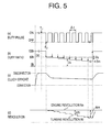
- FIG. 5 is a time chart representing the contents of the torque point learning control according to the present invention, whereby (a) shows the duty pulse output from the ECU 16 , (b) shows the change of the duty ratio D thereof, (c) virtually shows the clutch stroke of the wet multiplate clutch 3 for ease of comprehension, and (d) shows the changes in the revolution of the engine E (engine revolution Ne) and the revolution of the turbine 5 (turbine revolution Nt).
- the duty ratio D 100(%)
- the clutch is completely disconnected. Therefore, the turbine 5 revolves with the pump 4 , and the turbine revolution Nt coincides with the engine revolution Ne. Thereafter, learning is commenced when a prescribed learning starting condition is satisfied at time t 2 .
- the value of the start duty D 0 is determined such that the clutch will not on no account reach the target torque point even if there are variances, but made to approach the torque point as much as possible.
- the torque capacity remains at 0 when the duty ratio D moves from 100(%) to 60(%). It is therefore advisable that this type of invalid portion be connected at once.
- the start duty D 0 is predetermined based on experimental data as illustrated in FIG. 3 .
- the clutch connection speed is reduced extremely by making the connection width per cycle small.
- the diminution of the duty ratio per cycle is given as the step duty Ds (0.048(%) in the present embodiment), and the duty ratio D is lowered one Ds at a time for each control performed.
- the duty D of each control performed is a value of having deducted the step duty Ds from the previous value, and this is given as a gradual connection duty Dk.
- the turbine revolution Nt decreases against the engine revolution Ne. That is, the output side is stopped with the brake in a state where the gear of the transmission is in use, and the output side of the clutch is therefore unable to revolve. Contrarily, the pump 4 continues to be driven by the engine E. Therefore, if the clutch is connected further, the input side of the clutch; that is, the turbine 5 , tries to stop and gradually reduces its revolution, and, simultaneously, the sliding between the pump 4 and the turbine 5 gradually increases, and the turbine revolution Nt gradually decreases against the engine revolution Ne.
- the duty ratio D value at such time is learned by the ECU 16 as the learned torque point value Dm.
- the learning is substantially over upon storing such learned torque point value Dm, and the entire learning control (learning mode) is ended upon completely disconnecting the clutch thereafter.
- the torque point may be suitably learned even in a wet multiplate clutch, and this may be employed in various clutch controls, such as for switching the connection speed upon accurately knowing the torque point differing for each clutch. And, by absorbing the variances and individual differences of the clutch or the control devices thereof, the wet multiplate clutch may be connected with the same feeling in any vehicle.
- this learning is conducted after waiting a prescribed time upon detecting that the revolution difference ⁇ N became a prescribed value Nm or more.
- Nm a prescribed value
- the learning is conducted after a prescribed time ⁇ t 1 longer than a prescribed cycle ⁇ t elapses upon the detection of the turbine revolution Nt decreasing a prescribed revolution Nm against the engine revolution Ne.
- the waiting time ⁇ t 1 1 (sec) is an exemplification, and the length of the waiting time may be suitably changed.
- the response delay may be absorbed during clutch connection, an accurate learning value corresponding to the true torque point may be learned, and a large connection shock even in an ordinary clutch connection control may be prevented.
- the clutch connection control after the learning of the torque point is as follows.
- the duty ratio of the value (large value) slightly on the disconnection side in comparison to the learned torque point value Dm is foremost provided to the clutch solenoid valve CSV.
- This is referred to as a single connection control.
- the invalid portions of the clutch are rapidly connected thereby, and the connection time may be shortened.
- the duty ratio is subtracted in small step duties.
- the clutch is gradually connected as a result thereof, and the clutch connection shock may be prevented thereby.
- FIG. 8 is a condition transition diagram showing the transition of the clutch control phase.
- Torque point learning may be conducted arbitrarily pursuant to the intention of the driver.
- the driver foremost operates the shift lever into neutral(N).
- the clutch since the clutch is disconnected when the gear is in neutral during a standard control of a clutch, and connected when the gear is operated, the clutch will automatically disconnect by operating the shift lever to N.
- the routine enters the learning mode, and proceeds to the learning complete disconnection phase 102 .
- the transition condition T 1 at such time satisfies:
- the HSA switch 26 is turned on.
- Satisfaction of the learning condition of time t 1 in FIG. 5 and FIG. 6 implies the satisfaction of the aforementioned transition condition T 1 .
- the clutch is completely disconnected pursuant to the clutch complete disconnection phase 101 prior to time t 1 , and the clutch is completely disconnected pursuant to the learning complete disconnection phase 102 after time t 1 .
- the transition condition phase T 2 implies that:
- the routine proceeds to the learning gradual connection phase 103 , and the clutch connection is automatically commenced.
- the gear change into the second gear is the signal for commencing the learning.
- conditions may also be suitably changed or added in this transition condition T 2 .
- the second gear is an exemplification, and any gear may be used so as long as the output side of the clutch can be stopped with the brake. Nevertheless, the gear must be operated in one of the gears. Since the vehicle (truck or the like) in the present embodiment often starts in second gear, the second gear is used in the learning since this is realistic.
- the routine proceeds to the learning stop phase 104 when the transition condition T 3 from this learning gradual connection phase 103 is satisfied.
- the transition condition phase T 3 implies that:
- the duty ratio D when (1) is satisfied is retained for a prescribed time (plurality of cycles) in order to retain the clutch in the current condition.
- the duty ratio D at such time is temporarily incorporated in the ECU 16 , and judged is whether this value is the normal value as the learning value by comparing prescribed conditions. If normal, this value is newly learned as a new learning value Dm. The old learning value stored previously will be deleted at such time.
- condition (1)′ may be rephrased such that the turbine revolution Nt became less than 1 ⁇ 2 of the engine revolution Ne.
- condition (1) may be replaced with:
- the engine revolution Ne will decrease by being dragged pursuant to the decrease of the turbine revolution Nt, and the torque learning point may be determined upon viewing the degree of decrease in the engine revolution Ne.
- the diminution of the engine revolution Ne is set to 50 (rpm).
- the transition condition phase T 4 implies that:
- Conditions (2) through (6) particularly imply that it is not an appropriate situation for implementing the learning, and, even at the time the conditions of the learning complete disconnection phase 102 and learning gradual connection phase 103 are satisfied, the routine proceeds to the learning completion phase 105 .
- transition conditions T 6 and T 5 from the learning complete disconnection phase 102 and learning gradual connection phase 103 to the learning completion phase 105 are equal to T 4 .
- the transition condition T 7 is satisfied pursuant to this output, and the routine exits the learning mode and returns to the standard control, and arrives at the control stop mode 106 .
- control is basically an open control, and, the ECU 16 outputs a duty pulse in accordance with a prescribed predetermined program as shown in FIG. 9, and the clutch is connection in accordance therewith.
- FIG. 9 is a time chart representing the contents of the clutch connection control.
- the horizontal axis is time t, and the vertical axis is the duty ratio D output from the ECU 16 .
- the solid line is a line diagram to be the base prior to correction, and the broken line is a line diagram (after-correction 1 , 2 ) of two patterns after-correction.
- the map is prepared in advance based on experiments or the like such that the various optimum values reflecting the driving condition of the vehicle may be obtained.
- the base width of the learned torque point value is stored in the ECU 16 beforehand as Dtb.
- Dtb 53.5(%).
- the start duty Dst 0 is a value slightly to the disconnection side (large) in comparison to the base value Dtb of the learned torque point value, and the clutch is thereby connected at once up to a point close to the torque point.
- the waiting time ⁇ t 3 after the start duty is longer in comparison to the diminution cycle ⁇ ts.
- ⁇ t 3 is 0.2 (s) upon an upshift, and 0.5 (s) upon a downshift.
- the response delay of the clutch may be absorbed as in the case of learning.
- the value of n may be selected from the map.
- the step duty Ds 0 is set to be a value larger than the step duty Ds during the learning, or, in other words, the gradual connection of the clutch is conducted more slowly during learning than normal.
- the overall connection time is approximately 1 to 3 seconds, but a longer time; for example, approximately 5 to 6 seconds, is used for the connection during the learning.
- the learned torque point value is renewed to Dlt 1 , which is smaller than the base value Dtb (after-correction 1 ). Then, the start duty and end duty are corrected as follows, and the duty line diagram becomes the base line diagram moved parallel to the connection side as shown with the broken line of after-correction 1 .
- Ded 1 Dst 1 ⁇ Dse.
- the clutch connection control of after-correction 1 is implemented by employing the start duty Dst 1 and end duty Ded 1 .
- the subsequent clutch connection control employs the base value of the start duty and end duty obtained from the map for each control upon correcting it based on the difference A of the base value Dtb and renewal value Dlt 1 of the learned torque point value.
- After-correction 1 is an example where the renewal value Dlt 1 of the learned torque point value became smaller than the base value Dtb
- after-correction 2 is an example where the renewal value Dlt 2 became larger than the base value Dtb.
- Ded 2 Dst 2 ⁇ Dse.
- the clutch connection control of after-correction 2 is implemented by employing the start duty Dst 2 and end duty Ded 2 .
- the subsequent clutch connection control also employs the base value of the start duty and end duty obtained from the map for each control upon correcting it based on the difference B of the base value Dtb and renewal value Dlt 2 of the learned torque point value.
- embodiments of the present invention are not limited to the above.
- the learning method contrary to the method of gradually connecting the clutch as shown in FIG. 5 and FIG. 6, there is a method of gradually disconnecting the clutch.
- the clutch is completely connected simultaneously (time t 2 ) with the satisfaction of the learning commencement condition, and, after broadly disconnecting the clutch upon outputting a start duty D 0 (40% for example), the clutch is gradually disconnected upon increasing the duty ratio D one step duty Ds at a time.
- the difference N of the engine revolution Ne and turbine revolution Nt becomes a prescribed value Nm or less
- the ECU 16 learns the value of the duty ratio at such time as the learned torque point value Dm.
- the waiting time is set to ⁇ t 2 at the time the start duty D 0 is output, and, when the difference N of the engine revolution Ne and turbine revolution Nt becomes a prescribed value Nm or less, similar to the above, the waiting time is set to ⁇ t 1 .
- the control here is also an open control, and, the ECU 16 outputs a duty pulse in accordance with a prescribed predetermined program as shown in FIG. 11, and the clutch is connection in accordance therewith.
- the horizontal axis is time t
- the vertical axis is the duty D output from the ECU 16 .
- assumed is a case of a so-called garage shift upon starting the vehicle; that is, a state where the driver operates the shift from neutral to the starting gear while the brake is in use and the vehicle is in an idling state, and a creep is generated as a result of the clutch being connected.
- the horizontal axis is time t
- the vertical axis is the revolution
- the engine revolution Ne is shown with a solid line
- the clutch revolution Nt is shows with a chain line.
- the gear-in is completed at time t 0 , and a gear-in signal is sent from the gear position sensor 24 to the ECU 16 .
- the start duty Dst is constantly predetermined so as to prevent the generation of an excess clutch connection shock in consideration of the clutch being broadly connected up to a point close to the torque point and variances in the torque point.
- the start duty Ds is experientially or experimentally determined so as to be such deviated value or more.
- this start duty Dst is retained for a prescribed time ⁇ t 3 (0.2 (sec) during an upshift and 0.5 (sec) during a downshift in the present embodiment), and the output of the first gradual connection Dk 1 is commenced after the elapse of such time ⁇ t 3 .
- the reason for waiting the elapse of the prescribed time ⁇ t 3 is because, as described above, even if the start duty Dst is output, the pressing of the clutch plate will not begin until the clutch piston makes a small stroke (approximately 2 mm) in the allowance, and, therefore, there is a response delay in which a connection state comparable to the start duty Dst cannot be immediately obtained.
- the response delay can be absorbed, and the subsequent gradual connection control can be performed as aimed.
- the output of the first gradual connection duty Dk 1 is commenced at time t 1 after the elapse of time ⁇ t 3 .
- the first gradual connection duty Dk 1 is a duty wherein the clutch is gradually connected in a relatively fast speed, and is a value obtained by decreasing the first step duty Ds 1 from the previous duty value.
- the first step duty Ds 1 is set to a relatively large value, and here it is 0.4%.
- the duty is decreased one step duty Ds 1 at a time in order to conduct a first gradual connection at a speed faster than the gradual connection of prior inventions.
- the diminution cycle ⁇ tk 1 of the gradual connection duty Dk 1 is made equal to one control cycle ⁇ t in the present embodiment, but this, for example, may be made equal to a plurality of control cycles n ⁇ t.
- the second gradual connection duty Dk 2 is a duty wherein the clutch is gradually connected in a relatively slow speed, and is a value obtained by decreasing the second step duty Ds 2 from the previous duty value.
- the second step duty Ds 2 is set to a relatively small value, and here it is 0.02%.
- the duty is decreased one step duty Ds 2 at a time in order to conduct a second gradual connection at the same speed as with the gradual connection of prior inventions.
- the diminution cycle ⁇ tk 2 of the gradual connection duty Dk 2 is made equal to one control cycle ⁇ t in the present embodiment, but this, for example, may be made equal to a plurality of control cycles n ⁇ t.
- redundancy can be maintained and the successful combination of the time lag and shock at the time of clutch connection can be sought even when the optimum starting duty value varies or deviates due to disturbances.
- the garage shock and time lag can be effectively prevented, thereby enabling a smooth start.
- the gradual connection speed is switched to a lower speed when the condition of Nt ⁇ Ntke is satisfied. This is because there are cases where the turbine revolution Nt becomes lower than Ntke prior to the revolution ⁇ N becoming more than Nke, for example, when the engine revolution is lower than a standard idling revolution.
- step 104 the condition of ⁇ N ⁇ Nke or Nt ⁇ Ntke is satisfied.
- the wet friction clutch referred to in the present invention was a multiplate clutch in the foregoing embodiments, this may also be, for example, a single plate clutch.
- the fluid pressure referred to in the present invention was a hydraulic pressure, this may also be, for example, another fluid pressure such as pneumatic pressure.
- the transmission referred to in the present invention was a constantly engaged manual transmission in the foregoing embodiments, this may also be a constantly engaged automatic transmission, or a planetary gear automatic transmission as in an AT vehicle.
- the engine may also be diesel, gasoline, or other types.
- a superior effect is yielded of being able to absorb the response delay during the clutch connection, accurately learn the true torque point during the torque point learning, and prevent a large clutch connection shock during an ordinary clutch connection control.
Landscapes
- Engineering & Computer Science (AREA)
- General Engineering & Computer Science (AREA)
- Physics & Mathematics (AREA)
- Fluid Mechanics (AREA)
- Mechanical Engineering (AREA)
- Hydraulic Clutches, Magnetic Clutches, Fluid Clutches, And Fluid Joints (AREA)
Applications Claiming Priority (6)
| Application Number | Priority Date | Filing Date | Title |
|---|---|---|---|
| JP2001085304A JP4810742B2 (ja) | 2001-03-23 | 2001-03-23 | クラッチ接続方法 |
| JP2001-085304 | 2001-03-23 | ||
| JP2001-085303 | 2001-03-23 | ||
| JP2001085303A JP4742434B2 (ja) | 2001-03-23 | 2001-03-23 | クラッチの制御方法及びトルク点学習方法 |
| JP2001093252A JP2002295529A (ja) | 2001-03-28 | 2001-03-28 | クラッチのトルク点学習方法 |
| JP2001-093252 | 2001-03-28 |
Publications (2)
| Publication Number | Publication Date |
|---|---|
| US20020183912A1 US20020183912A1 (en) | 2002-12-05 |
| US6658341B2 true US6658341B2 (en) | 2003-12-02 |
Family
ID=27346337
Family Applications (1)
| Application Number | Title | Priority Date | Filing Date |
|---|---|---|---|
| US10/103,363 Expired - Lifetime US6658341B2 (en) | 2001-03-23 | 2002-03-21 | Clutch torque point learning method and clutch control method |
Country Status (3)
| Country | Link |
|---|---|
| US (1) | US6658341B2 (fr) |
| EP (3) | EP1596087B1 (fr) |
| DE (3) | DE60221919T2 (fr) |
Cited By (15)
| Publication number | Priority date | Publication date | Assignee | Title |
|---|---|---|---|---|
| US20050187070A1 (en) * | 2004-02-23 | 2005-08-25 | Aisin Seiki Kabushiki Kaisha | Hydraulic pressure characteristic value setting method for automatic transmission |
| US20060272919A1 (en) * | 2005-06-03 | 2006-12-07 | Jatco Ltd | Hydraulic clutch control system and method |
| CN100436891C (zh) * | 2004-02-06 | 2008-11-26 | 五十铃自动车株式会社 | 车辆用动力传递装置的发动机控制装置 |
| US20100057317A1 (en) * | 2006-11-22 | 2010-03-04 | Nobuyuki Iwao | Half-engage clutch point learning device for wet multiple disk clutch |
| US20100063699A1 (en) * | 2008-09-10 | 2010-03-11 | Gm Global Technology Operations, Inc. | System and method for determining the engagement point of a clutch |
| US20100102558A1 (en) * | 2008-03-31 | 2010-04-29 | Amsc Windtec Gmbh | Control system for wind energy converters |
| US20120109439A1 (en) * | 2010-11-01 | 2012-05-03 | Jatco Ltd. | Control apparatus for vehicle and control method therefor |
| US8579759B2 (en) | 2010-11-01 | 2013-11-12 | Jatco Ltd | Vehicle control apparatus and vehicle control method |
| US8636620B2 (en) | 2010-10-28 | 2014-01-28 | Jatco Ltd | Automatic transmission |
| US20140032063A1 (en) * | 2012-07-27 | 2014-01-30 | GM Global Technology Operations LLC | Clutch return spring pressure learning during a coasting maneuver |
| US8672805B2 (en) | 2011-02-03 | 2014-03-18 | Jatco Ltd | Vehicle control apparatus and vehicle control method |
| US8725375B2 (en) | 2010-11-01 | 2014-05-13 | Jatco Ltd. | Hydraulic control apparatus for vehicle |
| US8763736B2 (en) | 2010-11-02 | 2014-07-01 | Jatco Ltd | Control apparatus and method for hybrid vehicle |
| US9506509B1 (en) * | 2015-09-10 | 2016-11-29 | Ford Global Technologies, Llc | Clutch control using dither |
| US10138958B2 (en) * | 2015-11-20 | 2018-11-27 | Hyundai Autron Co., Ltd. | Method of learning touch point of clutch |
Families Citing this family (13)
| Publication number | Priority date | Publication date | Assignee | Title |
|---|---|---|---|---|
| JP3712193B2 (ja) * | 2001-12-10 | 2005-11-02 | 本田技研工業株式会社 | 動力伝達装置における摩擦係合要素の係合制御方法 |
| JP3826783B2 (ja) | 2001-12-13 | 2006-09-27 | いすゞ自動車株式会社 | 車両の動力伝達装置 |
| DE10333602A1 (de) * | 2003-07-24 | 2005-02-17 | Daimlerchrysler Ag | Vorrichtung zum Betätigen einer Drehmomentübertragungseinheit |
| DE102006042357A1 (de) * | 2006-09-08 | 2008-03-27 | Zf Friedrichshafen Ag | Verfahren zur Detektierung des Anlegepunktes einer Kupplung, insbesondere einer nassen Anfahrkupplung |
| DE102007012246A1 (de) * | 2007-03-14 | 2008-09-18 | Zf Friedrichshafen Ag | Verfahren und Vorrichtung zur Steuerung einer Kupplung |
| FR2929673B1 (fr) * | 2008-04-04 | 2010-08-27 | Peugeot Citroen Automobiles Sa | Procede de determination automatique du point de lechage d'un embrayage par apprentissage |
| DE102009023078B4 (de) | 2008-06-05 | 2021-10-14 | Schaeffler Technologies AG & Co. KG | Verfahren zum Steuern eines Kriechvorgangs und Antriebsstrang hierzu |
| FR2935767B1 (fr) * | 2008-09-05 | 2011-05-20 | Peugeot Citroen Automobiles Sa | Procede d'apprentissage d'un point de patinage d'un embrayage pour vehicule hybride |
| US9115772B2 (en) * | 2013-09-30 | 2015-08-25 | Cnh Industrial America Llc | System and method for automatically calibrating the clutches within a transmission of a work vehicle |
| JP6176192B2 (ja) | 2014-06-20 | 2017-08-09 | トヨタ自動車株式会社 | 車両の制御装置 |
| JP6754209B2 (ja) * | 2016-03-31 | 2020-09-09 | 本田技研工業株式会社 | リニアソレノイドバルブの電流制御方法 |
| KR102383232B1 (ko) * | 2016-12-15 | 2022-04-05 | 현대자동차 주식회사 | 하이브리드 차량의 엔진 클러치 전달토크 보정 방법 및 그 보정 장치 |
| CN115143209B (zh) * | 2022-05-26 | 2024-02-20 | 潍柴动力股份有限公司 | 车辆离合器自学习方法、装置、设备、介质及车辆 |
Citations (11)
| Publication number | Priority date | Publication date | Assignee | Title |
|---|---|---|---|---|
| US4388987A (en) | 1981-03-03 | 1983-06-21 | International Harvester Co. | Hydromechanical transmission employing lockup clutch |
| US4836057A (en) | 1985-02-19 | 1989-06-06 | Kabushiki Kaisha Komatsu Seisakusho | Method of controlling speed change clutches in a transmission |
| US5082097A (en) | 1989-12-05 | 1992-01-21 | Dickey-John Corporation | Transmission controller |
| US5509867A (en) * | 1994-05-16 | 1996-04-23 | Eaton Corporation | Engine flywheel torque determination method/system |
| US5601172A (en) | 1994-08-01 | 1997-02-11 | Case Corporation | Power take off clutch engagement control system for cold weather starting |
| US5634867A (en) * | 1994-09-19 | 1997-06-03 | Eaton Corporation | Main clutch reengagement control for a double clutch downshift |
| US5738609A (en) * | 1994-10-22 | 1998-04-14 | Automotive Products, Plc | Clutch control system |
| JPH11236931A (ja) | 1998-02-23 | 1999-08-31 | Isuzu Motors Ltd | 坂道発進補助装置付クラッチ自動制御車両 |
| US6022295A (en) | 1998-11-12 | 2000-02-08 | Eaton Corporation | Touch point identification for vehicle master clutch |
| EP1002687A2 (fr) | 1998-11-18 | 2000-05-24 | Eaton Corporation | Commande du couple de ralenti pour l'embrayage principal automatisé d'un véhicule |
| JP2000266159A (ja) | 1999-03-12 | 2000-09-26 | Isuzu Motors Ltd | 流体継手装置 |
-
2002
- 2002-03-19 EP EP05012040A patent/EP1596087B1/fr not_active Expired - Lifetime
- 2002-03-19 EP EP02006208A patent/EP1243806B1/fr not_active Expired - Lifetime
- 2002-03-19 EP EP05012039A patent/EP1596086B1/fr not_active Expired - Lifetime
- 2002-03-19 DE DE60221919T patent/DE60221919T2/de not_active Expired - Lifetime
- 2002-03-19 DE DE60221918T patent/DE60221918T2/de not_active Expired - Lifetime
- 2002-03-19 DE DE60205970T patent/DE60205970T2/de not_active Expired - Lifetime
- 2002-03-21 US US10/103,363 patent/US6658341B2/en not_active Expired - Lifetime
Patent Citations (11)
| Publication number | Priority date | Publication date | Assignee | Title |
|---|---|---|---|---|
| US4388987A (en) | 1981-03-03 | 1983-06-21 | International Harvester Co. | Hydromechanical transmission employing lockup clutch |
| US4836057A (en) | 1985-02-19 | 1989-06-06 | Kabushiki Kaisha Komatsu Seisakusho | Method of controlling speed change clutches in a transmission |
| US5082097A (en) | 1989-12-05 | 1992-01-21 | Dickey-John Corporation | Transmission controller |
| US5509867A (en) * | 1994-05-16 | 1996-04-23 | Eaton Corporation | Engine flywheel torque determination method/system |
| US5601172A (en) | 1994-08-01 | 1997-02-11 | Case Corporation | Power take off clutch engagement control system for cold weather starting |
| US5634867A (en) * | 1994-09-19 | 1997-06-03 | Eaton Corporation | Main clutch reengagement control for a double clutch downshift |
| US5738609A (en) * | 1994-10-22 | 1998-04-14 | Automotive Products, Plc | Clutch control system |
| JPH11236931A (ja) | 1998-02-23 | 1999-08-31 | Isuzu Motors Ltd | 坂道発進補助装置付クラッチ自動制御車両 |
| US6022295A (en) | 1998-11-12 | 2000-02-08 | Eaton Corporation | Touch point identification for vehicle master clutch |
| EP1002687A2 (fr) | 1998-11-18 | 2000-05-24 | Eaton Corporation | Commande du couple de ralenti pour l'embrayage principal automatisé d'un véhicule |
| JP2000266159A (ja) | 1999-03-12 | 2000-09-26 | Isuzu Motors Ltd | 流体継手装置 |
Cited By (25)
| Publication number | Priority date | Publication date | Assignee | Title |
|---|---|---|---|---|
| CN100436891C (zh) * | 2004-02-06 | 2008-11-26 | 五十铃自动车株式会社 | 车辆用动力传递装置的发动机控制装置 |
| US7524264B2 (en) | 2004-02-06 | 2009-04-28 | Isuzu Motors Limited | Vehicle controller of a vehicle power transmission device |
| US20050187070A1 (en) * | 2004-02-23 | 2005-08-25 | Aisin Seiki Kabushiki Kaisha | Hydraulic pressure characteristic value setting method for automatic transmission |
| US7204786B2 (en) | 2004-02-23 | 2007-04-17 | Aisin Seiki Kabushiki Kaisha | Hydraulic pressure characteristic value setting method for automatic transmission |
| US20060272919A1 (en) * | 2005-06-03 | 2006-12-07 | Jatco Ltd | Hydraulic clutch control system and method |
| US7445107B2 (en) * | 2005-06-03 | 2008-11-04 | Jatco Ltd | Hydraulic clutch control system and method |
| AU2007322805B2 (en) * | 2006-11-22 | 2012-05-17 | Isuzu Motors Limited | Half-engage clutch point learning device for wet multiple disk clutch |
| US20100057317A1 (en) * | 2006-11-22 | 2010-03-04 | Nobuyuki Iwao | Half-engage clutch point learning device for wet multiple disk clutch |
| CN101542154B (zh) * | 2006-11-22 | 2012-11-14 | 五十铃自动车株式会社 | 湿式多板离合器的半离合点学习装置 |
| US9212709B2 (en) | 2006-11-22 | 2015-12-15 | Isuzu Motors Limited | Half-engage clutch point learning device for wet multiple disk clutch |
| US20100102558A1 (en) * | 2008-03-31 | 2010-04-29 | Amsc Windtec Gmbh | Control system for wind energy converters |
| US8154143B2 (en) * | 2008-03-31 | 2012-04-10 | AMSC Austria GmbH | Wind energy converter comprising a superposition gear |
| US8024098B2 (en) * | 2008-09-10 | 2011-09-20 | GM Global Technology Operations LLC | System and method for determining the engagement point of a clutch |
| US20100063699A1 (en) * | 2008-09-10 | 2010-03-11 | Gm Global Technology Operations, Inc. | System and method for determining the engagement point of a clutch |
| US8636620B2 (en) | 2010-10-28 | 2014-01-28 | Jatco Ltd | Automatic transmission |
| US20120109439A1 (en) * | 2010-11-01 | 2012-05-03 | Jatco Ltd. | Control apparatus for vehicle and control method therefor |
| US8725375B2 (en) | 2010-11-01 | 2014-05-13 | Jatco Ltd. | Hydraulic control apparatus for vehicle |
| US8725333B2 (en) * | 2010-11-01 | 2014-05-13 | Jatco Ltd | Control apparatus for vehicle and control method therefor |
| US8579759B2 (en) | 2010-11-01 | 2013-11-12 | Jatco Ltd | Vehicle control apparatus and vehicle control method |
| US8763736B2 (en) | 2010-11-02 | 2014-07-01 | Jatco Ltd | Control apparatus and method for hybrid vehicle |
| US8672805B2 (en) | 2011-02-03 | 2014-03-18 | Jatco Ltd | Vehicle control apparatus and vehicle control method |
| US20140032063A1 (en) * | 2012-07-27 | 2014-01-30 | GM Global Technology Operations LLC | Clutch return spring pressure learning during a coasting maneuver |
| US8831844B2 (en) * | 2012-07-27 | 2014-09-09 | GM Global Technology Operations LLC | Clutch return spring pressure learning during a coasting maneuver |
| US9506509B1 (en) * | 2015-09-10 | 2016-11-29 | Ford Global Technologies, Llc | Clutch control using dither |
| US10138958B2 (en) * | 2015-11-20 | 2018-11-27 | Hyundai Autron Co., Ltd. | Method of learning touch point of clutch |
Also Published As
| Publication number | Publication date |
|---|---|
| EP1596086A1 (fr) | 2005-11-16 |
| US20020183912A1 (en) | 2002-12-05 |
| EP1596086B1 (fr) | 2007-08-15 |
| EP1243806B1 (fr) | 2005-09-07 |
| DE60221919T2 (de) | 2008-05-15 |
| EP1596087A1 (fr) | 2005-11-16 |
| DE60221918T2 (de) | 2008-05-08 |
| DE60221918D1 (de) | 2007-09-27 |
| DE60205970D1 (de) | 2005-10-13 |
| DE60205970T2 (de) | 2006-06-29 |
| EP1243806A2 (fr) | 2002-09-25 |
| EP1243806A3 (fr) | 2002-11-13 |
| DE60221919D1 (de) | 2007-09-27 |
| EP1596087B1 (fr) | 2007-08-15 |
Similar Documents
| Publication | Publication Date | Title |
|---|---|---|
| US6658341B2 (en) | Clutch torque point learning method and clutch control method | |
| US8290668B2 (en) | Control apparatus and method for automatic transmission | |
| US8612104B2 (en) | Clutch control device and μ correction coefficient calculating method | |
| US7722500B2 (en) | Control device and control method for automatic transmission | |
| US10131358B2 (en) | Control apparatus of the idle rotation speed of the internal combustion engine of a vehicle with an automatic transmission and a torque converter | |
| JP3826783B2 (ja) | 車両の動力伝達装置 | |
| US20070062772A1 (en) | Method for operating a drive train of a motor vehicle | |
| JP2002295529A (ja) | クラッチのトルク点学習方法 | |
| JP4178761B2 (ja) | クラッチの制御方法 | |
| JP3994675B2 (ja) | クラッチのトルク点学習方法 | |
| US6889804B2 (en) | Clutch control method | |
| JP3855672B2 (ja) | クラッチのトルク点学習方法 | |
| JP4360039B2 (ja) | クラッチのトルク点学習方法 | |
| JP4742434B2 (ja) | クラッチの制御方法及びトルク点学習方法 | |
| JP4146118B2 (ja) | クラッチの制御方法 | |
| JP5023416B2 (ja) | クラッチの制御方法 | |
| JP4810742B2 (ja) | クラッチ接続方法 | |
| JP2001301494A (ja) | 機械式自動変速機の変速制御装置 | |
| JP2003021175A (ja) | クラッチの制御方法 | |
| JP4830481B2 (ja) | 自動変速機の変速制御装置 | |
| JP2003240108A (ja) | ギヤ段検出装置 |
Legal Events
| Date | Code | Title | Description |
|---|---|---|---|
| AS | Assignment |
Owner name: ISUZU MOTORS LIMITED, JAPAN Free format text: ASSIGNMENT OF ASSIGNORS INTEREST;ASSIGNORS:INOUE, EIJI;SHINOJIMA, TAKUMI;REEL/FRAME:012715/0960 Effective date: 20020311 |
|
| STCF | Information on status: patent grant |
Free format text: PATENTED CASE |
|
| FEPP | Fee payment procedure |
Free format text: PAYOR NUMBER ASSIGNED (ORIGINAL EVENT CODE: ASPN); ENTITY STATUS OF PATENT OWNER: LARGE ENTITY |
|
| FPAY | Fee payment |
Year of fee payment: 4 |
|
| FEPP | Fee payment procedure |
Free format text: PAYOR NUMBER ASSIGNED (ORIGINAL EVENT CODE: ASPN); ENTITY STATUS OF PATENT OWNER: LARGE ENTITY Free format text: PAYER NUMBER DE-ASSIGNED (ORIGINAL EVENT CODE: RMPN); ENTITY STATUS OF PATENT OWNER: LARGE ENTITY |
|
| FPAY | Fee payment |
Year of fee payment: 8 |
|
| FPAY | Fee payment |
Year of fee payment: 12 |