US6629645B2 - Water mixing valve apparatus - Google Patents
Water mixing valve apparatus Download PDFInfo
- Publication number
- US6629645B2 US6629645B2 US10/062,844 US6284402A US6629645B2 US 6629645 B2 US6629645 B2 US 6629645B2 US 6284402 A US6284402 A US 6284402A US 6629645 B2 US6629645 B2 US 6629645B2
- Authority
- US
- United States
- Prior art keywords
- valve
- temperature
- water
- mixing valve
- control system
- Prior art date
- Legal status (The legal status is an assumption and is not a legal conclusion. Google has not performed a legal analysis and makes no representation as to the accuracy of the status listed.)
- Expired - Lifetime
Links
- XLYOFNOQVPJJNP-UHFFFAOYSA-N water Substances O XLYOFNOQVPJJNP-UHFFFAOYSA-N 0.000 title claims abstract description 246
- 238000012512 characterization method Methods 0.000 claims abstract description 54
- 230000008859 change Effects 0.000 claims description 34
- 230000001052 transient effect Effects 0.000 claims description 28
- 238000001514 detection method Methods 0.000 claims description 13
- 239000003990 capacitor Substances 0.000 claims description 12
- 230000004044 response Effects 0.000 description 26
- 230000033001 locomotion Effects 0.000 description 25
- 239000012530 fluid Substances 0.000 description 17
- 238000004891 communication Methods 0.000 description 8
- 238000007789 sealing Methods 0.000 description 8
- 230000009471 action Effects 0.000 description 7
- 238000009434 installation Methods 0.000 description 7
- 238000000034 method Methods 0.000 description 6
- 230000000694 effects Effects 0.000 description 4
- 238000012545 processing Methods 0.000 description 4
- 239000000523 sample Substances 0.000 description 4
- 230000003044 adaptive effect Effects 0.000 description 3
- 230000003750 conditioning effect Effects 0.000 description 3
- 230000006870 function Effects 0.000 description 3
- 230000002159 abnormal effect Effects 0.000 description 2
- 230000005540 biological transmission Effects 0.000 description 2
- 238000004422 calculation algorithm Methods 0.000 description 2
- 238000013016 damping Methods 0.000 description 2
- 230000007423 decrease Effects 0.000 description 2
- 238000001914 filtration Methods 0.000 description 2
- 231100001261 hazardous Toxicity 0.000 description 2
- 238000005286 illumination Methods 0.000 description 2
- 238000012544 monitoring process Methods 0.000 description 2
- 230000010355 oscillation Effects 0.000 description 2
- 230000008569 process Effects 0.000 description 2
- 238000012546 transfer Methods 0.000 description 2
- XQMVBICWFFHDNN-UHFFFAOYSA-N 5-amino-4-chloro-2-phenylpyridazin-3-one;(2-ethoxy-3,3-dimethyl-2h-1-benzofuran-5-yl) methanesulfonate Chemical compound O=C1C(Cl)=C(N)C=NN1C1=CC=CC=C1.C1=C(OS(C)(=O)=O)C=C2C(C)(C)C(OCC)OC2=C1 XQMVBICWFFHDNN-UHFFFAOYSA-N 0.000 description 1
- 238000004458 analytical method Methods 0.000 description 1
- 238000013459 approach Methods 0.000 description 1
- 238000004364 calculation method Methods 0.000 description 1
- 238000010276 construction Methods 0.000 description 1
- 230000003247 decreasing effect Effects 0.000 description 1
- 230000003111 delayed effect Effects 0.000 description 1
- 238000012938 design process Methods 0.000 description 1
- 230000001627 detrimental effect Effects 0.000 description 1
- 230000004069 differentiation Effects 0.000 description 1
- 230000009977 dual effect Effects 0.000 description 1
- 238000004146 energy storage Methods 0.000 description 1
- 230000009474 immediate action Effects 0.000 description 1
- 230000036039 immunity Effects 0.000 description 1
- 230000001788 irregular Effects 0.000 description 1
- 230000007774 longterm Effects 0.000 description 1
- 239000000463 material Substances 0.000 description 1
- 238000007620 mathematical function Methods 0.000 description 1
- 230000007246 mechanism Effects 0.000 description 1
- 230000008450 motivation Effects 0.000 description 1
- 238000002360 preparation method Methods 0.000 description 1
- 230000035945 sensitivity Effects 0.000 description 1
- 239000002453 shampoo Substances 0.000 description 1
- 238000004088 simulation Methods 0.000 description 1
- 239000000344 soap Substances 0.000 description 1
- 230000036962 time dependent Effects 0.000 description 1
- 230000001960 triggered effect Effects 0.000 description 1
- 238000005406 washing Methods 0.000 description 1
Images


Classifications
-
- G—PHYSICS
- G05—CONTROLLING; REGULATING
- G05D—SYSTEMS FOR CONTROLLING OR REGULATING NON-ELECTRIC VARIABLES
- G05D23/00—Control of temperature
- G05D23/01—Control of temperature without auxiliary power
- G05D23/13—Control of temperature without auxiliary power by varying the mixing ratio of two fluids having different temperatures
- G05D23/1393—Control of temperature without auxiliary power by varying the mixing ratio of two fluids having different temperatures characterised by the use of electric means
-
- F—MECHANICAL ENGINEERING; LIGHTING; HEATING; WEAPONS; BLASTING
- F16—ENGINEERING ELEMENTS AND UNITS; GENERAL MEASURES FOR PRODUCING AND MAINTAINING EFFECTIVE FUNCTIONING OF MACHINES OR INSTALLATIONS; THERMAL INSULATION IN GENERAL
- F16K—VALVES; TAPS; COCKS; ACTUATING-FLOATS; DEVICES FOR VENTING OR AERATING
- F16K11/00—Multiple-way valves, e.g. mixing valves; Pipe fittings incorporating such valves
- F16K11/02—Multiple-way valves, e.g. mixing valves; Pipe fittings incorporating such valves with all movable sealing faces moving as one unit
- F16K11/06—Multiple-way valves, e.g. mixing valves; Pipe fittings incorporating such valves with all movable sealing faces moving as one unit comprising only sliding valves, i.e. sliding closure elements
- F16K11/072—Multiple-way valves, e.g. mixing valves; Pipe fittings incorporating such valves with all movable sealing faces moving as one unit comprising only sliding valves, i.e. sliding closure elements with pivoted closure members
- F16K11/074—Multiple-way valves, e.g. mixing valves; Pipe fittings incorporating such valves with all movable sealing faces moving as one unit comprising only sliding valves, i.e. sliding closure elements with pivoted closure members with flat sealing faces
-
- F—MECHANICAL ENGINEERING; LIGHTING; HEATING; WEAPONS; BLASTING
- F16—ENGINEERING ELEMENTS AND UNITS; GENERAL MEASURES FOR PRODUCING AND MAINTAINING EFFECTIVE FUNCTIONING OF MACHINES OR INSTALLATIONS; THERMAL INSULATION IN GENERAL
- F16K—VALVES; TAPS; COCKS; ACTUATING-FLOATS; DEVICES FOR VENTING OR AERATING
- F16K19/00—Arrangements of valves and flow lines specially adapted for mixing fluids
- F16K19/006—Specially adapted for faucets
-
- F—MECHANICAL ENGINEERING; LIGHTING; HEATING; WEAPONS; BLASTING
- F16—ENGINEERING ELEMENTS AND UNITS; GENERAL MEASURES FOR PRODUCING AND MAINTAINING EFFECTIVE FUNCTIONING OF MACHINES OR INSTALLATIONS; THERMAL INSULATION IN GENERAL
- F16K—VALVES; TAPS; COCKS; ACTUATING-FLOATS; DEVICES FOR VENTING OR AERATING
- F16K29/00—Arrangements for movement of valve members other than for opening and closing the valve, e.g. for grinding-in, for preventing sticking
Definitions
- the present invention relates to a water mixing valve apparatus and, more particularly, to improvements in the control system of a water mixing valve apparatus having a servo controlled mixing valve.
- This known mixing valve apparatus has a problem when it is installed in a non-linear environment. For instance, where a mixing valve is installed in a water system having a higher pressure cold water supply, the first part of movement of the mixing valve will have little effect in raising the outlet temperature and the outlet temperature will be very sensitive to movement of the valve in a later small range.
- a mixing valve apparatus including:
- a mixing valve for mixing water from a cold water inlet and a hot water inlet and supplying the mixed water to a water outlet, the water inlets and outlets being for connection to an external water system;
- valve servo for moving the position of the valve
- control system characterises he external water system in which the mixing valve is connected and optimizes control of the valve according to he characterisation.
- the control system can adapt the way it controls the mixing valve according to the properties of the external water system In particular, for a given temperature change at a particular point in the temperature range, the control system can move the mixing valve by a different amount according to how the external water system has been characterised.
- the control system uses an outlet temperature sensor with a control loop, it can optimise control of the valve by varying, according to the characterisation, the amount of movement of the valve to correct a difference between actual and desired temperature as detected by the temperature sensor.
- the control loop in effect employs a gain which varies through the valves range according to the characterisation.
- the characterisation takes account of at least one of inlet water flows, pressures and temperatures. This enables the mixing valve apparatus to be optimised for a wide variety of external water systems.
- the characterisation used by the control system can be selected by the user, for instance by means of an input selector. In this way, the user merely preselects the type of external water system in which the mixing valve apparatus is installed or changes the selection until an optimum response is observed.
- control system could automatically determine the characterisation on the basis of operating conditions of the valve.
- control system determines the characterisation of the external water system on the basis of the properties of the water at the outlet of the mixing valve compared to the controlled position of the valve to produce those properties.
- the operating conditions may include the mixed temperature at the outlet and the position of the mixing valve. Furthermore, they may include the cold water inlet temperature or an estimation thereof. Similarly, the operating conditions can include a measure of the change of position of the mixing valve with respect to a change in the actual mixed water temperature at the outlet.
- control system By additionally considering the cold water inlet temperature, the control system only requires data relating to two other operating positions to characterise the external system.
- the operating conditions may additionally include the temperature of the input hot water.
- control system only requires data relating to one intermediate position of the valve to characterise the external system.
- control system is able to characterise the external system more quickly and easily.
- control system is continuously adaptive such that, should the properties of the external system change, the characterisation will also change. In other words, the applicable response or gain for the operating range will change.
- control system may also determine the characterisation of the external water system with respect to time. In this way, the control system can predict conditions where the properties of the external water system change over time. For instance, the control system could compensate for the temperature of the hot water inlet decreasing over time as the temperature in a hot water supply tank decreases. Similarly, the control system could compensate for dead leg in supply pipes according to time since the mixing valve was last used and/or changes as the temperature of a supply pipe comes up to the temperature of the water it carries.
- control system makes use of the characterisation to move the valve to a position predicted to produce the required temperature at the water outlet.
- a mixing valve apparatus including:
- a mixing valve for mixing water from a cold water inlet and a hot water inlet and supplying the mixed water to a water outlet, the inlets and outlets being for connection to an eternal water system;
- valve servo for moving the position of the valve
- control system stores information relating position of the valve and valve servo to temperature at the outlet such that, upon start-up, when a desired temperature is selected the valve servo is initially operated to move the valve to the position stored for the selected temperature.
- control system uses a temperature sensor in the outlet together with a control loop
- the control system positions the valve without using the control loop for a short predetermined period of time. In this way, when the control loop is again used, the valve position and the actual temperature should be close to the required position and temperature such that the required temperature can be reached more quickly and with less oscillation in temperature.
- mixing valves will be used in systems which are shut down and restarted within a short period of time. For instance, in a domestic shower, the shower may be turned off briefly while the user is applying soap or shampoo.
- the control system assumes that the conditions of the water system have not changed and jump starts a start up control loop to restore the valve to its position as previously used.
- a mixing valve apparatus including:
- a mixing valve for mixing water from a cold water inlet and a hot water inlet and supplying the mixed water to a water outlet, the inlets and outlets being for connection to an external water system;
- valve servo for moving the position of the valve
- the control system assumes that the conditions of the external water system have not changed and jump starts a start-up control loop to restore the valve to its position as previously used.
- valve may be driven directly to the position it had when it was last used.
- valve is moved directly to a position suitable for producing the desired outlet conditions.
- This is particularly useful for a mixing valve used to control both flow and temperature.
- the control loop may be activated once the valve has reached the required position.
- a mixing valve apparatus including:
- a mixing valve for variably mixing hot and cold water
- valve servo for moving the mixing valve
- control system for operating the valve servo so as to provide a desired mixed water temperature
- control panel remote from the mixing valve and valve servo for providing a control signal to the control system to select the desired temperature
- control system includes a maximum temperature selector by which a user may specify a maximum mixed water temperature selectable by the control panel;
- control panel includes a display of selectable mixed water temperatures
- the display only showing temperatures up to the selected maximum mixed water temperature
- the display has a fixed predetermined extent, the scale of which is varied according to the selected maximum mixed water temperature.
- the scale makes fill use of the available display and, furthermore, for low maximum temperatures, the scale can be increased to show changes in temperature with greater accuracy.
- the maximum temperature selector is provided proximate the mixing valve and the valve servo.
- control panel Since the control panel is provided remote from the mixing valve and the valve servo and since the maximum temperature selector is provided proximate the mixing valve and valve servo, it is not possible for a user to inadvertently change the temperature specified by the maximum temperature selector. Hence, a user may freely select temperatures using the control panel without any danger of selecting a temperature beyond that specified by the maximum temperature selector.
- the control panel may include a member movable between two predetermined end positions to select the mixed water temperature, one of the predetermined end positions selecting the selected maximum mixed water temperature and the scale of selectable mixed water temperatures between the two predetermined end positions being adjusted according to the selected maximum mixed water temperature.
- a mixing valve apparatus including:
- valve servo for moving the mixing valve
- an electrical energy store for powering tee valve servo and control system in the event that no power is received by the electrical power input, in such event, the control system operating the valve servo to move the valve to a position of no flow.
- the electrical energy store provides power to close the valve and shut off supply of water from the outlet.
- valves having and preferably the apparatus has a valve member with apertures for hot and cold water and movable between a position of no flow and positions of mixed flow between maximum hot and maximum cold.
- the valve member may provide a no flow position at two positions, one adjacent the maximum cold position and one adjacent the maximum hot position.
- control system preferably operates the valve servo to move the valve member to the nearest of the two no flow positions.
- the valve is moved to its off position most quickly and with the least amount of energy.
- the control system switches off power to unnecessary components of the mixing valve apparatus so as to conserve power.
- control system only provides power to components essential for operating the mixing valve. For instance, any illumination of an associated control panel could be turned off.
- control system could switch off power to any control loop for the valve on the basis that the operating conditions will not change over the short period of time following the power failure.
- the electrical energy store is a capacitor. This provides a longer service life than a battery and, also, allows energy storage at a higher voltage.
- the capacitor While power is received by the electrical power input, the capacitor may be charged to the highest possible safe voltage, for instance, at least 40 volts or a legislated maximum voltage, such as 42.4 volts.
- control system may determine the remaining electrical energy stored in the electrical energy store and operate the valve servo to move the valve to the position of no flow when the remaining electrical energy equals that needed to move the valve to the position of no flow.
- the valve servo may comprise a stepper motor.
- the control system preferably operates the stepper motor by half steps when power is received by the electrical power input and by whole steps in the event that no power is received by the electrical power input.
- the control system operates the valve servo to move the mixing valve to a position of no flow using the optimum servo trajectory resulting in the use of minimum power.
- the servo In normal operation, the servo is usually operated to provide an optimum response by moving the valve quickly to a desired position Depending on the characteristics of the servo, it will also be possible to operate the servo in such a manner that it moves to a desired position with minimum use of power.
- the size of the electrical energy store may be minimised or the time during which the mixing valve apparatus may continue to operate during a power failure may be maximised.
- a mixing valve apparatus including:
- a mixing valve for mixing water from a cold water inlet and a hot water inlet and supplying the mixed water to a water outlet;
- a detector for detecting at least one predetermined position of the mixing valve
- control system for sequentially operating the stepper motor to move the mixing valve in one direction past said at least one predetermined position and in an opposite direction past said at least one predetermined position, thereby to determine with reference to the detector the back lash in the gear train.
- control system when the control system is required to move the mixing valve in a direction opposite to the direction in which it was last moved, it can operate the stepper motor by an additional amount equal to the backlash in the gear train so as to move the mixing valve accurately to the required position. This can significantly improve the accuracy of the control system.
- the control system is preferably responsive to a control signal to move the mixing valve to a position indicated by the control signal, the control system operating the stepper motor accordingly, taking account of the backlash in the gear train.
- control signal could be derived from a temperature sensor in the water outlet for controlling the water outlet temperature.
- control signal may also be derived from a demand temperature input by a user.
- a mixing valve apparatus including:
- valve having at least one sealing surface against which at least one resilient seal presses
- valve servo for moving the valve
- control system in the absence of a control signal to move the valve within a predetermined period, the control system operates the valve automatically so as to keep the resilient seal from sticking to the sealing surface.
- the predetermined period is at least 24 hours. This is particularly useful for mixing valves used in showers. showers are often used regularly at the same time each day. Hence, the control system will operate the valve servo if the shower is not operated by the user at this regular time.
- Movement of the valve need only be sufficient to prevent the resilient seals from sticking to the sealing surfaces.
- the valve is arranged such that it can be moved sufficiently to move the resilient seals relative to their sealing surfaces without the valve providing flow therethrough.
- a mixing valve is controlled by means of a control loop having a sensor in the outlet, it is often necessary to have a damped response.
- the control loop is used to maintain a particular temperature of water at the outlet, it is undesirable for the control loop to be undamped, since the system will unduly oscillate when moving to a new temperature and will overreact to changes in temperature resulting from minor changes to the inlet streams, for instance due to other usage on the same water supply.
- a cold water supply failures it is extremely important that the system reacts quickly, for instance to shut off the water flow before a user becomes scalded.
- a mixing valve apparatus including:
- a mixing valve for mixing water from a cold water inlet and a hot water inlet and supplying the mixed water to a water outlet, the inlets and outlets being for connection to an external water system;
- valve servo for moving the position of the valve
- control system for operating the valve servo and thereby controlling flow from the water outlet, the control system including a temperature sensor for providing an indication of the temperature at the water outlet and a control loop for comparing the desired temperature with that provided by the temperature sensor so as to operate the valve servo;
- control system additionally includes a transient detector for determining transients in the water flow from the temperature indicated by the temperature sensor and overriding the control loop to control the valve servo in the event of a transient.
- control loop may provide the desired damped response for controlling the outlet temperature.
- control loop can be overridden so as to allow the control system to take immediate action in view of the detected temperature changes.
- the normal control loop no longer has control over movement of the valve and the transient detector causes the valve to be moved rapidly to a safe position.
- valve servo is controlled to rapidly reduce the supply of water from the hot water inlet to the water outlet to substantially zero.
- the transient detector continuously monitors the rate of change in temperature indicated by the temperature sensor.
- the transient detector may predict the actual temperature at the water outlet from the rate of change in temperature indicated by the temperature sensor and the time constant of the temperature sensor.
- the transient detector can predict an actual rate of change which is much greater.
- the transient detector can predict an unacceptable rise in temperature such that the control system can take appropriate action.
- a mixing valve apparatus including:
- a mixing valve for mixing water from a cold water inlet and a hot water inlet and supplying the mixed water to a water outlet, the inlets and outlets being for connection to an external water system;
- valve servo for moving the position of the valve
- control system includes an error detection circuit for detecting at least one of the following:
- the mixing valve apparatus is able to operate safely despite any faults which may occur.
- control system can operate the mixing valve in a fail-safe mode, for instance moving the valve to full cold, to a safe intermediate temperature or shutting off the flow of water from the outlet.
- the error detection circuit only recognises indications of the temperature between predetermined limits as valid temperatures and determines failure of the temperature sensor when the indication temperature is outside the predetermined limits.
- the temperature limits may be set such that if the temperature sensor goes open circuit or closed circuit, the error detection circuit determines an error. This prevents the control system driving the valve to full cold or full hot in response to an erroneous signal indicating maximum or minimum temperature.
- the intermediate maximum temperature may be selected using a potentiometer, the maximum selectable intermediate maximum temperature being selected with the potentiometer at its maximum resistance and a fixed resistor being provided in series with the potentiometer such that higher resistances are detected as errors.
- the potentiometer for selecting the intermediate maximum temperature becomes disconnected, the open circuit is not recognised as a high intermediate maximum temperature and the control system takes appropriate action; for instance issuing a warning and shutting off the valve or using an internal default intermediate maximum temperature.
- the sum temperature selectable as the intermediate maximum temperature corresponds to a closed circuit such that an unwanted short circuit fails safe.
- the error detection circuit regularly checks for valid signals from the control panel and detects an error when no valid signal is received.
- the error detection circuit checks for valid signal levels, and, for digital control panels, the error detection circuit checks that the control panel can communicate.
- control system can take appropriate action, for instance shutting off the valve.
- a mixing valve apparatus including:
- a mixing valve for mixing water from a cold water inlet and a hot water inlet and supplying the mixed water to a water outlet, the inlets and outlets being for connection to an external water system;
- valve servo for moving the position of the valve
- control system stores information relating position of the valve and valve servo to temperature at the outlet such that, upon start-up, when a desired temperature is selected the valve servo is initially operated to move the valve to the position stored for the selected temperature.
- a mixing valve apparatus including:
- a mixing valve for variably mixing hot and cold water
- valve servo for moving the mixing valve
- control system for connection to a remotely located control panel and for operating the valve servo so as to provide a desired mixed water temperature according to the control panel;
- control system includes an input port suitable for connection selectively to an analogue control panel and a digital control panel.
- the input port includes six lines of which two lines are suitable for analog control signals.
- the input port includes an input termination circuit.
- the input termination circuit includes;
- the second resistor has a higher impedance with respect to the first resistor.
- a method of communicating with a mixing valve apparatus having a mixing valve for variably mixing hot and cold water, a valve servo for moving the mixing valve and a control system with a digital interface allowing input of a digital signal so as to cause the control system to operate the valve servo and provide a desired nixed water temperature comprising:
- control message of 8 bits having, in order, a destination address byte, a source address byte, a command number byte, three payload bytes and two CRC bytes.
- the command number has at least six values representing respectively report system status, switch valve on or off, set temperature, switch pump on or off, report temperature and report pump status.
- FIG. 1 illustrates schematically a remote controlled water mixing valve apparatus embodying the present invention
- FIG. 2 illustrates a cross section through a valve suitable for use with the present invention
- FIG. 3 illustrates a valve member for use in the valve of FIG. 2
- FIG. 4 illustrates typical profiles for the mixing of hot and cold water supplies
- FIG. 5 illustrates schematically a control loop for the control system of FIG. 1;
- FIG. 6 illustrates the profile for an external water system as split into temperature bands
- FIGS. 7 ( a ) and ( b ) illustrate embodiments of control panels
- FIG. 8 illustrates a control system using an additional electrical energy store.
- FIG. 9 illustrates examples of temperature versus valve position
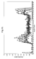
- FIG. 10 illustrates a graph of gradients of the curves of FIG. 9
- FIG. 11 represents the maximum gradient curve for FIGS. 9 and 10.
- FIG. 12 illustrates au input termination circuit
- the water mixing apparatus includes a mixing valve 2 which is operated by a valve servo 4 under the control of a control system 6 .
- the control system 6 receives a control signal from a remote control panel 8 .
- control panel 8 is connected to the control system 6 by means of a cable or wire 10 .
- any appropriate communication may be provided between the control panel 8 and control system 6 , including wireless systems.
- the control panel 8 is at least able to indicate in the control signal a desired water outlet temperature. However, it may also indicate other properties to the control system 6 in the control signal.
- a signal may be transmitted from the control system 6 to the control panel 8 in order to display information on the control panel 8 .
- the mixing valve 2 includes at least two inlets 12 and 14 . These inlets 12 , 14 are respectively for transfer fluid of different properties to the mixing valve 2 . Hence, inlet 12 may provide a flow of cold water to the mixing valve 2 and inlet 14 may provide a flow of hot water to the mixing valve 2 .
- Fluid mixed by the mixing valve 2 flows out of the mixing valve 2 via an outlet 16 .
- the mixing valve 2 is operated by means of a valve servo 4 , for example a stepper motor.
- the valve servo 4 is controlled by the control system 6 so as to move the mixing valve 2 to a position providing the desired mixed output flow through outlet 16 .
- FIG. 1 illustrates a temperature sensor 18 located in the mixed flow of fluid so as to detect the temperature of mixed fluid.
- the temperature sensor 18 is positioned in the outlet 16 .
- the temperature sensor 18 can also be positioned in the mixing chamber of the mixing valve 2 provided that it is at a position which will give a correct representation of the mixed outlet temperature.
- control system 6 can operate the valve servo 4 so as to move the mixing valve 2 to a position providing a desired output temperature.
- FIG. 2 illustrates a cross-section through a preferred mixing valve 2 for use in the apparatus of FIG. 1
- the mixing valve 2 includes a valve member 20 as illustrated in FIG. 3 .
- Inlets 12 , 14 include cup seals 22 , 24 which seal against the face 26 of valve member 20 .
- valve member 20 includes tapered apertures 28 .
- one of the inlets is opened fully to the mixing chamber of the mixing valve 2 and then, as flow from that inlet is progressively reduced, flow from the other inlet is progressively increased. In this way, any desired mix from the inlets 12 , 14 can be obtained.
- valve member 20 may be rotated by a shaft 30 extending through the mixing valve 2 .
- the shaft 30 is rotated by the valve servo 4 either directly or by means of a gear train.
- the gear train may be provided separately or may be housed internally of the valve servo 4 .
- mixing valve 2 is used in a system having equal pressure and flow characteristics for the supply to both inlets 12 and 14 , it is possible to provide a linear mixing response with respect to movement of the valve. For mixing hot and cold fluids, this is illustrated by the solid line in the graph of FIG. 4 .
- the system will have different pressure and flow characteristics on different supply pipes.
- the cold water may be of higher pressure than the hot water or the hot water of higher pressure than the cold water.
- FIG. 4 illustrates two situations.
- the hot water is of higher pressure than the cold water
- the mixed outlet temperature will follow the characteristic illustrated by the broken line of FIG. 4 with reference A.
- the outlet temperature will follow the characteristic illustrated by the broken line of FIG. 4 having reference B.
- the water system can most simply be characterised as having one of three characterisations, namely a high pressure hot water system, an equal pressure system or a high pressure cold water system.
- the control system with a user operable switch 32 allowing selection of the appropriate characterisation for the system in which the mixing valve apparatus is installed.
- the switch 32 could be provided with only three states corresponding respectively to the three basic characterisations Equally, in another arrangement, it could be provided with additional states for intermediate characterisations. Alternatively, the switch could allow continuous selection of characterisations within a predetermined range.
- control system 6 is able to operate the valve servo 4 in a manner to optimise the response of the system, thereby achieving higher response times and a more stable control.
- control system 6 adjusts the position of the valve 2 at a rate appropriate with the actual change in mixing resulting from a change in position. In this way, the control system 6 can make the response of the control as fast as possible and also minimise overshoot.
- the control system 6 is able to select any desired output mix even without knowing the characterisation of the external system.
- the control system 6 can operate the valve servo 4 to move the mixing valve 2 more or less than would otherwise be expected for a given change of mix at the outlet.
- the control system 6 would operate the valve servo 4 to move the valve 2 less for temperatures at the lower end of the temperature range than for temperatures at the higher end of the temperature range.
- the gain varies with valve position and this information is used to optimize the control loop.
- valve position and outlet temperature for at least the usual operating range is chosen. This is then used to obtain any desired outlet temperature.
- Control loop gain need not be varied dynamically during movement of the valve between different positions since the characterization of the external system is sufficient for optimising control over at least the usual operating range
- control system 6 which automatically determines the characteristics of the system in which the mixing valve apparatus is installed.
- the control system 6 can automatically choose one of a predetermined number of different characterizations. It can compare how much it instructs the valve servo 4 to move the mixing valve 2 with respect to detected changes in mix, for instance changes in the temperature detected by the temperature sensor 18 .
- the control system can alternatively build up a profile of the mix response and, hence, control the mixing valve 2 more effectively.
- the resulting profile forms a characterization representing the operating range, thereby allowing the valve to be moved freely between different positions and outlet temperatures without the need to dynamically adjust control loop gain for each new position.
- control system 6 monitors the response curve on a continuous basis such that, if the response changes over time, the control system 6 changes its characterisation of the external system and changes its control of the valve servo 4 accordingly.
- the control system 6 may undergo a continuous learning process.
- control system 6 In order to have a complete and accurate profile for the characterisation, the control system 6 must operate the mixing valve 2 through the complete range of positions and resulting mixes. In this way, the control system 6 can build up any profile, even a profile of irregular form which does not correspond to any of the profiles illustrated in FIG. 4 .
- valve it may be undesirable for the valve to be moved through its complete range because it will take time and because a user may only want the mixing valve to operate with a single predetermined mix.
- the characterisation can be approximated by one of a predetermined selection of profiles such as those illustrated in FIG. 4, it is possible to more quickly and easily determine an appropriate characterisation.
- the characterisation can be approximated by one of a predetermined selection of profiles such as those illustrated in FIG. 4, it is possible to more quickly and easily determine an appropriate characterisation.
- by establishing at least 3 points with regard to valve position and mix properties it is possible to estimate an appropriate profile and to establish the required characteristics for the control system.
- a temperature sensor (not illustrated) in the cold inlet 12 to determine the cold temperature.
- an alternative is to use the temperature measured by temperature sensor 18 upon start-up. It will be appreciated that most systems, there will be some dead lag, i.e. a length of fluid in the pipes, between the hot fluid supply and the mixing valve 2 . Hence, upon start-up, no hot fluid will be mixed with the cold fluid and the temperature measured by the temperature sensor 18 will be the temperature of the dead lag of fluid. This temperature will usually be the ambient temperature of the building in which the system is installed. This, in turn, will be will be representative of the cold fluid temperature, though, in practice, will usually be slightly higher.
- control system 6 could measure the hot fluid temperature in the hot inlet 14 . This is not essential, but could be achieved using a temperature sensor (not illustrated) in the hot inlet 14 . In this way, the control system 6 would know the end points of the temperature profile and could estimate an appropriate characterisation with only one intermediate value for valve position versus outlet temperature.
- control system 6 determines whether the characterisation determined by the control system 6 is not limited only to the expected non linear profiles represented in FIG. 4 and discussed above.
- control system 6 can build up a representation of any characteristics of any system.
- the characteristics of a system can change with time. For instance, for a domestic water system after start-up, the temperature of the hot water at the hot water inlet 14 may increase as the supply pipes are brought up to the temperature of the hot water. Alternatively, one of the supplies may be fed from a source which decreases in pressure as water is used.
- the control system 6 may, therefore, monitor and keep a record of characterisation with respect to time. In this way, the control system 6 can change the characterisation which it applies to the system over time following start-up of the fluid flow.
- the control system may also choose an appropriate characterisation according to how long the mixing valve 2 has been in a no-flow state with both inlets 12 , 14 shut off. For example, in a domestic water supply, if the mixing valve 2 has been in a no-flow state for only 15 minutes, the water and pipes between the hot water source and the mixing valve 2 will not have cooled to room temperature so that, upon start-up, the control system 6 can apply a characterisation more appropriate than the usual. start-up characterisation.
- the control system 6 can assume that the operating conditions of the apparatus have not changed at all. In this way, the control system 6 can immediately apply the same characterisation as was used before the apparatus was shut down
- control system 6 does not store separate characterisations for various types of start-up as discussed above, it is still possible for it to optimise the start up procedure.
- control system 6 can mate use of its characterisations for normal running conditions and/or a record of the position of the valve 2 immediately before shut down.
- the mixing valve When the mixing valve is tuned on again only a short while after being turned off (for instance, a few minutes), then the input conditions can be assumed to have not changed. In this situation, if the demand mix has not changed since last use, the valve 2 can be driven immediately to the last stable position. Similarly, the control system 6 can assume that he previous characterisation still applies and drive the valve immediately to the position appropriate for the requested mix. In this way, the control system 6 ignores the current conditions, for instance as indicated by the temperature sensor 18 and the associated control loop, and returns control of the valve 2 to the control loop after only a short wait of for instance about 3 seconds. This gives the fastest possible start-up time.
- the mixing valve is turned on again after a long time of being off, for instance more than a few minutes, then the input conditions can be assumed to have changed. However, even in these circumstances, it is still possible to make use of the normal working characterisation used by the control system 6 to drive the valve to approximately the right position, i.e. using the learnt data about the average valve position for a given mix as represented by the characterisation. In these circumstance the control loop is restarted after a longer wait, for instance about 20 seconds, or if the mix is detected, for instance by the temperature sensor 18 , to be nearing the demand conditions.
- the system can also incorporate a further safety feature such that, if the temperature sensor 18 indicates an illegally high temperature the control system 6 overrides the processes discussed above and drives the mixing valve 2 to fill cold anyway.
- control system 6 may use a PID controller, since it is flexible enough to provide a stable and safe response for most conditions. However, it is difficult to optimise through calculation, simulation or experimentation.
- FIG. 5 illustrates an appropriate arrangement.
- the actual position (Pa) needs to be added to the position error (Pe) to give a demand position (Pd). This local feedback loop will insure the motor is driven as fast as possible at all times.
- the derivative term gives an output proportional to the rate of change of error. This gives two advantages. Firstly, in response to sudden temperature errors (eg. water pressure disturbances), the derivative action will produce a large compensating controller action Secondly, when the actuator is moving towards the demand temperature at speed, the derivative term will produce an output to slow the actuator. In this way, as the derivative term is increased, the proportional term can also be increased, improving the controller rise time.
- sudden temperature errors eg. water pressure disturbances
- the derivative term is limited primarily by system noise. As the derivative gain is increased, the noise which contains fast edges will cause the actuator to ‘chatter’ resulting in unnecessary motor and gear wear.
- the proportional gain is mainly limited by the thermistor time response.
- the time constants of the system can be considered fixed so it is only the instantaneous gain of the plant that is needed to keep the control loop critically damped. Start-up is also important and data about the correct position for a given temperature will allow an optimal start-up response.
- One limitation is that there is little time to perform complex mathematical functions on-line. Thus, if these have taken place they are preferably carried out off-line.
- the controller may calculate the new gain value when off in preparation for the next time the valve is operated. It does this because the processing overhead to calculate the new gas is quite high.
- a low cost microcontroller does not have sufficient processing power to rum the control algorithms and calculate the new gains at the same time.
- valve When the valve is off, the microcontroller has virtually no other processing to perform It is proposed that the valve should operate with 0.1. second cycle during which the algorithm checks the demand temperature, actual temperature, compares the two and calculates the error, then knowing the previous error the control can carry out any adjustment required. Significant processing speeds would be required to constantly re-calculate the gain values within the 0.1 second cycles.
- the plant response is split into 5 temperature bands and within each of these bands a single temperature/position co-ordinate is stored. This is illustrated in FIG. 6 .
- the co-ordinate is derived from a running average of stable points reached in this temperature band.
- the gain is defined by the number of actuator steps needed for a 1 degree change in temperature and is calculated off-line between each of the stored coordinates. The gain is extrapolated above and below the top and bottom points. Where no data has been collected a predefined ‘safe’ gain is used.
- controller (PD or otherwise) is adaptive and the correct gain is selected for the current temperature or position. It is defined as being proportional to the inverse of the plant gain. The constant of proportionality is tunable.
- a demand position is interpolated from the nearest recorded co-ordinate using the stored gain.
- the valve can thus be moved directly to the calculated position.
- the system will leave this mode if the demand temperature is reached or if the demand temperature is changed.
- the system will also leave this mode after a predetermined time. This time should be set slightly longer than the expected cold dead leg time (cold water in the hot pipe) as it will stop the actuator moving to the full hot position.
- the behaviour of the valve with different external water connections can be characterised during the design process. This will yield a graph (FIG. 9) containing a set of curves representing blended water temperature against valve position. Mathematical differentiation of these curves will produce a graph of gradients against valve position (FIG. 10 ). A new curve representing the maximum gradient at every position can be derived (FIG. 11 ). For the system to operate as fast as possible and to be stable for all external water connections the maximum controller gain must be proportional to the inverse of the maximum gradient curve at every position. In FIG. 11 the maximum controller gain (derived from the maximum gradient curve) is shown with respect to the actuator position, it has been averaged to give a smoother curve.
- the temperature of the hot water at the inlet 14 may be unsafe to be dispensed from the outlet 16 .
- the apparatus is to be used by, for instance, children or the elderly, there may be a danger of the control panel 8 being set to a temperature which is too high.
- the control system 6 may, itself be provided with an input 36 .
- Be input 36 is used to set the maximum temperature which can be selected by the control panel 8 .
- the control system 6 and mixing valve 2 will be generally inaccessible. Therefore, using the control panel 8 , the user will only be able to select temperatures up to the maximum temperature selected by the input 36
- the input 36 may take any suitable form, for example a slider or rotatable knob operating for instance a potentiometer or up and down buttons used in conjunction with a display on the control system 6 itself or on the control panel 8 .
- the input 36 could also be provided by a control which is operable only by a special tool, for instance a slotted head to be turned by a screwdriver.
- control knob may be provided with a corresponding display scale of unmarked dimensions.
- the display scale may range from “MIN” to “MAX” with a plurality of divisions in between.
- the display scale indicates specific values such as temperatures, it is preferable that the display is adjusted automatically according to preselection of the maximum temperature so as to show appropriate values up to the maximum value.
- control system can adjust the ranges and display of the control panel 8 accordingly.
- FIG. 7 ( a ) illustrates a control panel 8 having a slider 38 for selecting the desired temperature.
- the slider 38 may move from a minimum temperature position to a maximum temperature position 42 .
- the control system 6 allocates the maximum temperature position 42 to the maximum temperature selected by input 36 . In this way, the full range of movement of the slider 38 is available to select the desired temperature. Indeed, in normal use, the operator would be unaware of the maximum temperature setting.
- a display 44 may be provided to display the selected temperature.
- FIG. 7 ( b ) illustrates a control panel 8 with a similar slider 38 having maximum and maximum temperature positions 40 , 42 .
- the control panel 8 is provided with a display 46 providing a representation of the selectable temperature scale alongside the slider 38 .
- the display 46 includes segments 48 displaying selectable temperatures. Hence, the scale represented on the display 46 and the temperatures indicated in the segments 48 are determined according to the range of temperatures selectable up to the maximum selected by input 36 .
- the display 46 may be embodied as an LCD or such like and thereby easily allow a variety of scales and alphanumeric characters to be represented.
- control panel 8 may be any form of control panel 8 , such as those with rotary knobs.
- the system can control an external or internal water pump.
- This pump is switched on when the valve is opened and off when the valve is closed.
- the pump switch-on is delayed when the valve is opened. This allows the valve to move through the cold position before the pump increases the flow rate. This minimises the unwanted cold water supplied during start up.
- valve such as illustrated in FIGS. 2 and 3
- a valve servo controls a flow of fluid by means of a valve servo
- the valve will remain open indefinitely and continue to supply fluid.
- the control system 6 is provided with an electrical power input 50 and an electrical energy store 52 .
- the electrical energy store 52 is preferably embodied as an internal part of the control system 6 as illustrated in FIG. 1 .
- the control system 6 operates under the power of the electrical power input.
- power is supplied from the electrical energy store 52 .
- the control system 6 makes use of the energy available from the electrical energy store 52 to operate the valve servo 4 to move the valve to a closed position, in other words, to shut the valve off and drive it to a position in which no flow occurs through the valve.
- the electrical energy store 52 is preferably maintained in a charged state by the electrical power input 50 during normal use.
- the energy store 52 is of a rechargeable nature.
- Non-rechargeable batteries would obviously need replacing. Compared to capacitors, rechargeable batteries tend to have a lower energy density; need a complex charging circuit; and have a more limited charge/discharge life. They are also of generally low voltage such that it would be necessary to step up the voltage from about 1.5V to about 40V in order to drive the motor.
- the capacitor In order that the capacitor can provide sufficient power to operate the valve, it is preferred that it should be charged to a relatively high voltage since the energy stored is proportional to the square of voltage, but only increases linearly with the value of the capacitor. Ideally, the energy should be stored at the highest voltage possible.
- the capacitor is charged to at least 40 volts and preferably at least 50 volts.
- the energy is stored on the low voltage side of the transformer, there is a practical limitation of 42.4V imposed by the relevant safety standards in the United Kingdom. Hence, in this instance the energy would be stored at 42.2V.
- Mains 230V ac could be stepped down to a safe low voltage through a transformer and then rectified to d.c.
- an alternative approach would be to use a switched mode power supply solution. Such a system would require that the incoming 231 Vac mains is rectified to d.c. and the energy stored at this point.
- a switched mode power supply circuit would then be used to translate this down to a safe isolated d.c. voltage.
- control system 6 may estimate the power required to move the valve to its off position, i.e. with no flow. This will, of course, vary according to the current position of the valve.
- the control system 6 may also estimate the available amount of electrical energy remaining in the electrical energy store 52 .
- the control system 6 may allow the valve apparatus to continue operating with the selected flow until it determines that the energy stored in the electrical energy store 52 is approaching the amount required to shut off the valve.
- the control system 6 will not unnecessarily shut off the valve.
- the control system 6 may shut off power to unnecessary parts of the apparatus under its control.
- the control system 6 may only allow continued supply of power to some of the components in the overall apparatus. For instance, if the control panel 8 is provided with a display and/or illumination, this can be turned off. The control system 6 can be turned off and the valve actuator will only be operated in response to abnormal conditions. Similarly, digital communications with the control panel of other accessories can be turned off.
- control system will only allow the flow to continue provided it remains wit certain limits and not regardless of inlet conditions.
- the valve and valve servo are used with little consideration of power consumption, but more concern for optimising speed and control.
- the control system 6 may control the valve servo in a different manner.
- it may supply power to the valve servo in such a way as to optimise movement of the valve to its off position.
- the trajectory of movement of the valve servo and valve is chosen so as to bring the valve to its position of no flow using the minimum amount of energy as possible.
- the most efficient mode of the power supply could also be used where, for instance, a switch mode power supply is used.
- stepper motor As the valve servo. As is well known, it is possible to operate a stepper motor by half steps. Thus, it is proposed that, during normal use, in order to provide maximum control, the stepper motor would-be operated by half steps. However, in the event of a power failure, the control system 6 operates the stepper motor by whole steps in order to move the valve to its off position as quickly and efficiently as possible.
- control system 6 when used for supplying a mix of hot and cold water, the control system 6 may be configured so as normally to always move the valve to an off position adjacent maximum cold water supply. In this way, upon starting use of the apparatus, the user will always be provided with cold water before hot, thereby avoiding a user from being unnecessarily scalded.
- control system could be configured such that, in the event of a power failure, it moves the valve to the nearest off position, whether or not his is adjacent the hot or cold water supply.
- valve servo 4 Although it is possible for the valve servo 4 to be connected directly to the valve 2 , in order to achieve good control of the valve 2 , movement of the valve servo will often exceed that required for the valve 2 . In other words, a gear train is used between the valve servo and valve 2 . Unfortunately, gear trains of any type may result in some back lash. In other words, when reversing the direction of movement of the valve servo 4 , the back lash in the gear train will have to be taken up before movement in the valve 2 starts.
- the gear train is formed internally of the housing of the valve servo 4 .
- a sensor 54 may be provided on the valve 2 or at least on a shaft directly connected to the movement of the valve 2 .
- the control system 6 may then operate a start-up procedure to determine the back lash in the gear train.
- the detector 54 need only detect a single predetermined position of the valve 2 .
- the control system 6 then moves the valve servo in one direction by an amount sufficient to take up any back lash in the gear train and past the at least one position detected by the detector 54 . Having determined from the detector 54 that the valve 2 has moved past the predetermined position, the control system 6 then reverses the direction of the valve servo 4 until the valve 2 once again passes the position detected by the detector 54 .
- the amount by which the valve servo 4 is operated to return the valve 2 to the detected position will be the same as the amount by which it was moved away. However, in practice, the valve servo 4 will have to be operated by a greater amount to return the valve 2 to the detected position. The additional amount by which it is operated represents the back lash in the gear train.
- the control system can then use this information when operating the valve servo 4 to move the valve 2 during normal use.
- the control system 6 will operate the valve servo 4 by an additional amount to compensate for the back lash in the gear train.
- control system can achieve much greater accuracy and speed of operation.
- valves are constructed with resilient seals which press against sealing surfaces.
- the cup seals 22 , 24 seal against the surface 26 of the valve member 20 .
- the material making up the resilient seals may start to adhere to the sealing surface such that when the valve is next used the resilient seals may be damaged.
- the stiction effect of the seals on the disk surface 26 causes the operating torque to rise with time. High stiction between the seals and the disk surface could cause the valve to jam in the off position or could have a detrimental effect on the gear box in the long term.
- In-operation may occur for a number of reasons. For instance, where the apparatus of Figure us used for mixing hot and cold water for a domestic shower, the shower may be used only occasionally.
- the control system 6 may include a timer and may monitor how long it has been since the valve 2 was last operated. When the time since last operation exceeds a predetermined limit, the control system 6 may then operate the valve servo 4 so as to move the valve 2 . Movement of the valve 2 need only be very slight, in particular, enough only to slide the resilient seal in either direction. Preferably, the construction of the valve 2 is such that slight movement is possible in the no-flow state so that the valve and resilient seals can be moved sufficient to slide the seals without starting any flow through the valve 2 . Of course, even if this is not possible, the movement will be so small and so quick that barely any flow will occur through the value 2 .
- the valve would be operated every 24 hours.
- the control system 6 should use a predetermined period of more than 24 hours for automatic movement of the valve 2 .
- a period of approximately 30 hours allows for a user to be running slightly later than normal in his or her daily routine and, in comparison to a period of approximately 24 hours, would, in those circumstances, avoid the user hearing the automatic operation.
- a period of approximately 20 hours where the shower is used in the morning, it would not be operated until the middle of the night and, therefore, would not be noticed.
- control loop In a control system having a control loop based on the detected mix conditions, the control loop includes a gain and damping appropriate to give an optimum response under usual working conditions. However, it is now recognised that in some circumstances, such as failure in the installation or fluid supply, the response of the normal control loop will not be adequate. Hence, it is proposed that the control system 6 includes a transient detector control loop 56 independent of the normal temperature control loop and that it uses this to shut off the valve 2 during exceptional circumstances.
- control system as discussed above will attempt to minimise the error between a demand value, e.g. requested temperature, and an actual plant output value, e.g. measured temperature.
- a demand value e.g. requested temperature
- an actual plant output value e.g. measured temperature.
- no control system can react infinitely fast to changes in input conditions. It is possible to increase the gain of the feedback system such that a small change in error causes a large corrective action. However, this can lead to instability in the control loop under normal conditions.
- a transient detector control loop 56 should be provided independently of the normal control loop, either as a separate software routine or as an independent processor within the control system.
- the transient detector control loop 56 would continuously monitor the actual temperature, rather than the demand temperature. It is then arranged so as to predict what a faster temperature probe would have seen in the system.
- the transient detector 56 works by continuously monitoring the rate of change in temperature detected by the temperature sensor. By knowing the time constant of the sensor, the transient detector 56 can then predict what temperature the device is actually “seeing”. For example, a thermistor might take 0.3 seconds to register 30% of a change in temperature. In this case, if the transient detector 56 monitors a 4-C change in 0.3 seconds, it can predict an actual change of 12-C.
- the transient detector 56 detects that a safe time/temperature profile has been exceeded, it overrides the normal temperature control loop and forces the control system into a “transient” state.
- a profile of acceptable temperatures above the demanded value with respect to time can be used to trigger the transient detector if exceeded.
- the transient detector 56 If the transient detector 56 is triggered, there is no attempt to use the normal temperature control loop, for instance by dynamically changing the gain.
- the transient detector 56 suspends the normal temperature control loop (FIG. 5) takes control of the valve and causes the valve to be driven immediately to the full cold or off position. In particular, it ensures that the hot water is reduced to substantially zero.
- the transient detector 56 may then relinquish control to the normal temperature control loop again.
- the normal temperature control loop may be designed for optimum performance whilst the transient detector 56 provides a separate safeguard against unwanted transients in the water supply.
- control system 6 also includes an error detection circuit 58 for detecting errors in the apparatus and the operation of the system. In particular, it may then operate a fail-safe mode.
- the role of the error detection is to detect whether there is an abnormal fault condition which may have a safety implication and to take appropriate action.
- the temperature sensor for instance thermistor
- the temperature sensor can fail open-circuit or closed-circuit. If it fails open-circuit, for instance because a wire becomes detached, the high resistance can look like a cold temperature and, hence, the control loop will move the valve to full hot. On the other hand, a short-circuit failure will look like a very hot temperature and, hence, the valve will move to full cold.
- the normal range of interest would be 15-C to 55-C. Hence, it is proposed that should the system detect temperatures below or above these limits, then it will determine that an error has occurred and turn off the valve.
- a negative temperature coefficient (NTC) thermistor is used whereby the resistance fall with increasing temperature.
- the resistance of the thermistor is converted to a voltage level via signal conditioning circuitry with this voltage level being presented to an analogue to digital convertor.
- the signal conditioning circuitry can be designed such that the voltage levels are constrained to the dynamic range of the ADC (eg. 0V to 5V) and designed such that 0V (for example) corresponds to one extreme of temperature range (for example, the minimum) and 5V (for example) corresponds to another extreme of temperature (for example, the maximum) which it is desired to measure. Temperatures outside of these extremes would be clipped to 0V or 5V respectively.
- Another common failure is for he thermistor or connecting circuitry to short circuit such that the resistance appears very small. This condition can also be detected if the signal conditioning circuitry is scaled such that the maximum temperature measureable by the ADC can be known to be a temperature which can never occur under normal operating conditions.
- a good example is 100 dec C. in a water mixing valve. It will be recognised such that other maximum temperatures can also be selected.
- two comparators may be used which detect the illegal states and provide a single bit indication to the control system.
- the selectable maximum temperature control 36 may use a potentiometer to alter the selected maximum temperature. If the potentiometer were to fail (open circuit or short circuit) then a previously safe temperature, for instance 35° C., could potentially revert to the maximum selectable temperature of for instance 55° C. By associating the minimum position of the selectable temperature with zero resistance, then a short circuit will always fail safe and need not be detected. On the other hand, by associating the magnum selectable temperature with the maximum potentiometer resistance, it is possible to detect an open circuit, for instance by way of an external fixed resistor in series with the potentiometer.
- control panel 8 becomes disconnected from the control system 6 during use, this is a potentially hazardous situation.
- control system continually checks for valid signals from the control panel and switches the valve off if invalid conditions are detected. For analogue control panels, this requires checking valid signal levels and for digital control panels, this requires checking that the unit can communicate.
- valve controller can reconfigure itself accordingly. Additionally, if the control panel or accessory is disconnected, the controller will detect this and shut down.
- control panel 8 is connected to the control system 6 by means of a transmission path 10 .
- the transmission path 10 allows the connection of various control panels to the control system 6 .
- the control system 6 is provided with a control interface.
- the control system 6 may analyse it to determine its type.
- the system uses a single input port to support an analogue electronic control panel and a digital electronic control panel.
- the input port has 6 lines and they are configured as shown in table 1.
- the valve system can distinguish between the control panels and configure itself accordingly.
- the analogue control panel uses 2 lines varying between 0V and 5V to represent the demand temperature and the status of the control panel buttons.
- the digital panel uses the I 2 C Acess Buss digital communications protocol operating at 16 kHz to transfer data about the demand temperature and button presses.
- the system has the ability to identify which of the 2 panel types are connected by inspecting the signal levels on another line (line 6) on the input port.
- Analogue Line Valve Panel Digital Panel 1 1 M pull-up On/Off indicator N/C 2 Switched 5 V 5 V 5 V 3 1 M pull-down, 10 k Pot with 1 K SDA RC filter and series resistor to 51 R to 1 2 C GND 4 RC filter and Mode selector SCL 51 R to I 2 C 5 GND GND GND 6 1 M pull-up Flow indicator 10 k pull-down
- the digital communications uses two of the same input port lines as the analogue panel. The dual function of these lines is allowed by the configuration shown in FIG. 12 . Each electrical valve system input line is terminated in the same way.
- the clamp diodes D 1 and D 2 protect the terminating circuit from over and under voltage conditions.
- C 1 and R 1 are required by the digital communications.
- R 2 and C 2 provide filtering of the analogue input signals. When the digital communications are in use R 2 prevents the relatively high capacitance of C 2 from disrupting the communications.
- the presence of C 2 in close proximity to the ADC (analogue to digital converter) gives added noise immunity to the ADC.
- the shown values of R 2 and C 2 are not specific to the invention, they can be altered to tune the level of filtering on the analogue signals. It is a requirement that R 2 has high impedance with respect to R 1 .
- the digital protocol allows devices other than a control panel to communicate with the valve system. This could include pumps, bath fill systems, hand wasers, extractor fans, lighting systems or others.
- the protocol defines a message format shown in table 2.
- MSG_ENQUIRY Report system status 1 MSG_SET_MODE Switch valve on or off 2 MSG_SET_TEMP Set temperature (in eighths of a degree) 3 MSG_SET_FLOW Switch pump on or off 4 MSG_QUERY_TEMP Report temperature (in eighths of a 5 degree) MSG_QUERY_FLOW Report pump status 6
Landscapes
- Engineering & Computer Science (AREA)
- General Engineering & Computer Science (AREA)
- Mechanical Engineering (AREA)
- Physics & Mathematics (AREA)
- General Physics & Mathematics (AREA)
- Automation & Control Theory (AREA)
- Multiple-Way Valves (AREA)
- Control Of Temperature (AREA)
- Domestic Hot-Water Supply Systems And Details Of Heating Systems (AREA)
Applications Claiming Priority (3)
| Application Number | Priority Date | Filing Date | Title |
|---|---|---|---|
| GB0102356A GB2371634B (en) | 2001-01-30 | 2001-01-30 | Water mixing valve apparatus |
| GB0102356 | 2001-01-30 | ||
| GB0102356.3 | 2001-01-30 |
Publications (2)
| Publication Number | Publication Date |
|---|---|
| US20020153425A1 US20020153425A1 (en) | 2002-10-24 |
| US6629645B2 true US6629645B2 (en) | 2003-10-07 |
Family
ID=9907791
Family Applications (1)
| Application Number | Title | Priority Date | Filing Date |
|---|---|---|---|
| US10/062,844 Expired - Lifetime US6629645B2 (en) | 2001-01-30 | 2002-01-30 | Water mixing valve apparatus |
Country Status (4)
| Country | Link |
|---|---|
| US (1) | US6629645B2 (de) |
| EP (1) | EP1229418B1 (de) |
| DE (1) | DE60217198T2 (de) |
| GB (2) | GB2405224B (de) |
Cited By (38)
| Publication number | Priority date | Publication date | Assignee | Title |
|---|---|---|---|---|
| DE102005003451A1 (de) * | 2005-01-25 | 2006-07-27 | BSH Bosch und Siemens Hausgeräte GmbH | Verfahren und Vorrichtung zur Regelung der Temperatur von Mischwasser |
| EP1767840A2 (de) | 2005-09-27 | 2007-03-28 | Geberit Technik Ag | Motorisch betätigbare, hydraulische Ventilpatrone |
| US20070194148A1 (en) * | 2006-02-06 | 2007-08-23 | Rosko Michael S | Power sprayer |
| US20080164331A1 (en) * | 2007-01-05 | 2008-07-10 | Randall Paul Schmitt | Fluid delivery control system |
| US20080213446A1 (en) * | 2007-03-01 | 2008-09-04 | Feinberg Bruce G | Automated fryer refilling device and method |
| US20080213445A1 (en) * | 2007-03-01 | 2008-09-04 | Feinberg Bruce G | Automated fryer filtration device and method |
| US7448553B2 (en) | 2005-04-19 | 2008-11-11 | Masco Corporation Of Indiana | Fluid mixer |
| US20080289811A1 (en) * | 2007-05-23 | 2008-11-27 | Ats Japan Corp. | Constant temperature controller |
| US7458520B2 (en) | 2005-04-19 | 2008-12-02 | Masco Corporation Of Indiana | Electronic proportioning valve |
| US7475827B2 (en) | 2005-04-19 | 2009-01-13 | Masco Corporation Of Indiana | Fluid mixer |
| US7584898B2 (en) | 2005-07-01 | 2009-09-08 | Masco Corporation Of Indiana | Manual override for electronic proportioning valve |
| US7690395B2 (en) | 2004-01-12 | 2010-04-06 | Masco Corporation Of Indiana | Multi-mode hands free automatic faucet |
| US7850098B2 (en) | 2005-05-13 | 2010-12-14 | Masco Corporation Of Indiana | Power sprayer |
| US8028355B2 (en) | 2005-11-11 | 2011-10-04 | Masco Corporation Of Indiana | Integrated bathroom electronic system |
| US8089473B2 (en) | 2006-04-20 | 2012-01-03 | Masco Corporation Of Indiana | Touch sensor |
| US8118240B2 (en) | 2006-04-20 | 2012-02-21 | Masco Corporation Of Indiana | Pull-out wand |
| US8162236B2 (en) | 2006-04-20 | 2012-04-24 | Masco Corporation Of Indiana | Electronic user interface for electronic mixing of water for residential faucets |
| US8365767B2 (en) | 2006-04-20 | 2013-02-05 | Masco Corporation Of Indiana | User interface for a faucet |
| US8376313B2 (en) | 2007-03-28 | 2013-02-19 | Masco Corporation Of Indiana | Capacitive touch sensor |
| US20130075483A1 (en) * | 2010-05-21 | 2013-03-28 | Masco Corporation Of Indiana | Electronic shower user interface |
| US8438672B2 (en) | 2005-11-11 | 2013-05-14 | Masco Corporation Of Indiana | Integrated electronic shower system |
| US8469056B2 (en) | 2007-01-31 | 2013-06-25 | Masco Corporation Of Indiana | Mixing valve including a molded waterway assembly |
| US8561626B2 (en) | 2010-04-20 | 2013-10-22 | Masco Corporation Of Indiana | Capacitive sensing system and method for operating a faucet |
| US8613419B2 (en) | 2007-12-11 | 2013-12-24 | Masco Corporation Of Indiana | Capacitive coupling arrangement for a faucet |
| US8776817B2 (en) | 2010-04-20 | 2014-07-15 | Masco Corporation Of Indiana | Electronic faucet with a capacitive sensing system and a method therefor |
| US8944105B2 (en) | 2007-01-31 | 2015-02-03 | Masco Corporation Of Indiana | Capacitive sensing apparatus and method for faucets |
| US9175458B2 (en) | 2012-04-20 | 2015-11-03 | Delta Faucet Company | Faucet including a pullout wand with a capacitive sensing |
| US9243392B2 (en) | 2006-12-19 | 2016-01-26 | Delta Faucet Company | Resistive coupling for an automatic faucet |
| US9243756B2 (en) | 2006-04-20 | 2016-01-26 | Delta Faucet Company | Capacitive user interface for a faucet and method of forming |
| US9357881B2 (en) | 2012-03-31 | 2016-06-07 | Pitco Frialator, Inc. | Oil level detection system for deep fat fryer |
| US20170272844A1 (en) * | 2014-12-03 | 2017-09-21 | Grundfos Holding A/S | Electronic converter unit for retrofitting to an external part of a housing of a pump unit |
| US9885497B2 (en) * | 2015-04-22 | 2018-02-06 | Haier Us Appliance Solutions, Inc. | Method for operating a water heater appliance |
| US9938700B2 (en) | 2012-08-23 | 2018-04-10 | Elkay Manufacturing Company | Cold water delivery system |
| US10392786B2 (en) | 2015-01-19 | 2019-08-27 | Moen Incorporated | Electronic plumbing fixture fitting with electronic valve including piston and seat |
| US10481622B2 (en) | 2010-11-04 | 2019-11-19 | Magarl, Llc | Electrohydraulic thermostatic control valve |
| US10626803B2 (en) * | 2015-10-22 | 2020-04-21 | United Technologies Corporation | Apparatus and method for controlling and monitoring an electro-hydraulic servovalve |
| US11168897B2 (en) | 2018-08-24 | 2021-11-09 | Prexcel Solutions, Inc. | Water preconditioner system |
| US11267003B2 (en) | 2005-05-13 | 2022-03-08 | Delta Faucet Company | Power sprayer |
Families Citing this family (21)
| Publication number | Priority date | Publication date | Assignee | Title |
|---|---|---|---|---|
| FR2857722B1 (fr) * | 2003-07-17 | 2007-04-20 | Cotherm Sa | Vanne de melange |
| US7396412B2 (en) * | 2004-12-22 | 2008-07-08 | Sokudo Co., Ltd. | Coat/develop module with shared dispense |
| GB0500970D0 (en) * | 2005-01-18 | 2005-02-23 | Kohler Mira Ltd | Improvements in or relating to ablutionary Installations |
| GB2436606B (en) | 2006-03-29 | 2010-09-15 | Aqualisa Products Ltd | Water valve assembly |
| JP2008232478A (ja) * | 2007-03-19 | 2008-10-02 | Sanden Corp | 給湯装置 |
| DE102009057485A1 (de) * | 2009-12-10 | 2011-06-16 | Dieter Herber | Einfachwirkender elektromotorischer Stellantrieb |
| DE102012012515A1 (de) * | 2012-06-22 | 2013-12-24 | Auma Riester Gmbh & Co. Kg | Stellantrieb, Stellantriebanlage, Verfahren zum Betreiben eines Stellantriebs und Verfahren zum Betreiben einer Stellantriebanlage |
| DE102014004282A1 (de) * | 2014-03-26 | 2015-10-01 | Sew-Eurodrive Gmbh & Co Kg | Verfahren zum Betreiben eines Antriebssystems und Antriebssystem zur Durchführung eines Verfahrens |
| FR3019875B1 (fr) * | 2014-04-14 | 2016-05-13 | Vernet | Procede de detection d'un defaut de raccordement hydraulique d'une cartouche thermostatique electronique, cartouche thermostatique et mitigeur associe |
| US10209721B2 (en) * | 2016-08-18 | 2019-02-19 | Haier Us Appliance Solutions, Inc. | Hot water heater systems and methods for controlling electronic mixing valves |
| US10466727B2 (en) * | 2016-11-22 | 2019-11-05 | Haier US Appliance Solution, Inc. | Water supply system and a method for operating the same |
| US20180163993A1 (en) * | 2016-12-09 | 2018-06-14 | Haier Us Appliance Solutions, Inc. | Water heater appliance and a method for operating the same |
| US10642289B1 (en) | 2017-03-30 | 2020-05-05 | Alarm.Com Incorporated | Connected mixing valve for controlling water temperature |
| JP7034602B2 (ja) * | 2017-04-28 | 2022-03-14 | アズビル株式会社 | 温度調節計 |
| CN107420615B (zh) * | 2017-07-25 | 2021-11-26 | 青岛海尔智能技术研发有限公司 | 一种自动水温调节器及其出水温度调节方法 |
| US10795387B2 (en) * | 2018-02-12 | 2020-10-06 | Compal Electronics, Inc. | Water temperature control system and water temperature control method |
| JP7670740B2 (ja) * | 2020-06-19 | 2025-04-30 | ヘイル プロダクツ インク | 消防車バルブチェッカーシステム及び方法 |
| US11347246B2 (en) * | 2020-07-10 | 2022-05-31 | Haier Us Appliance Solutions, Inc. | Water heater appliances and methods for controlling a mixing valve with a park period |
| JP7527726B2 (ja) * | 2020-09-18 | 2024-08-05 | アール・ビー・コントロールズ株式会社 | 電子混合水栓 |
| GB2599956B (en) | 2020-10-19 | 2024-09-25 | Kohler Mira Ltd | Control system for one or more ablutionary devices |
| CN114440439B (zh) * | 2022-02-28 | 2024-09-10 | 武汉大学 | 一种医院用感应式开水器 |
Citations (27)
| Publication number | Priority date | Publication date | Assignee | Title |
|---|---|---|---|---|
| US3561484A (en) * | 1969-09-12 | 1971-02-09 | John F Taplin | Servo-controlled dual fluid mixing valve |
| US3561483A (en) * | 1969-08-06 | 1971-02-09 | John F Taplin | Dual fluid mixing valve with servomotor |
| US4189792A (en) * | 1978-09-18 | 1980-02-26 | Veach Carlos W | Push button controlled water system |
| GB2143343A (en) | 1983-07-13 | 1985-02-06 | Standard Telephones Cables Ltd | Thermostatically controlled mixer |
| FR2582418A1 (fr) | 1985-05-23 | 1986-11-28 | Knebel & Roettger Fa | Robinetterie melangeuse sanitaire |
| EP0227916A1 (de) | 1985-12-06 | 1987-07-08 | Giulio Stella | Elektronische Wassermischungsvorrichtung |
| JPS6389910A (ja) | 1986-10-03 | 1988-04-20 | Toto Ltd | 湯水混合装置 |
| JPS6389909A (ja) | 1986-10-03 | 1988-04-20 | Toto Ltd | 湯水混合装置 |
| EP0300639A1 (de) * | 1987-07-07 | 1989-01-25 | Inax Corporation | Duschanlage |
| US4854498A (en) | 1988-06-08 | 1989-08-08 | Stayton L Dean | Shower temperature control system |
| US4909435A (en) * | 1987-06-29 | 1990-03-20 | Matsushita Electric Industrial Co., Ltd. | Hot water supply system |
| JPH02150581A (ja) | 1988-11-29 | 1990-06-08 | Toto Ltd | 自動水栓 |
| EP0375259A2 (de) | 1988-12-23 | 1990-06-27 | Matsushita Electric Works, Ltd. | Warmwasserversorgungssystem |
| US4969598A (en) * | 1987-07-17 | 1990-11-13 | Memry Plumbing Products Corp. | Valve control |
| US5032992A (en) | 1986-07-23 | 1991-07-16 | American Standard Inc. | Electronic temperature control system |
| US5144975A (en) | 1991-12-10 | 1992-09-08 | Morris Polis | Automatic antifreeze back-up valve for sewer |
| JPH04331859A (ja) | 1991-05-07 | 1992-11-19 | Oki Electric Ind Co Ltd | ステッピングモータ閉ループ制御機構におけるバックラッシの補正方法 |
| US5174495A (en) | 1990-08-17 | 1992-12-29 | Friedrich Grohe Armaturenfabrik Gmbh & Co. | Adjusting and servicing a computer-controlled mixing valve |
| GB2263755A (en) | 1992-01-30 | 1993-08-04 | Mcmaster Christie Colin | Mixer valve for showers |
| GB2268302A (en) | 1992-06-26 | 1994-01-05 | Schlumberger Ind Ltd | Prepayment water supply systems |
| WO1998026339A1 (en) | 1996-12-12 | 1998-06-18 | The Unique Company Limited | Valve system for servo control of fluid flows |
| US5873518A (en) * | 1997-03-17 | 1999-02-23 | Emerson Electric Co. | Water valve assembly having a temperature and pressure sensing device integrated therein |
| US5979776A (en) * | 1998-05-21 | 1999-11-09 | Williams; Roderick A. | Water flow and temperature controller for a bathtub faucet |
| WO1999057381A1 (en) | 1998-05-04 | 1999-11-11 | American Standard International, Inc. | Touchless fluid supply interface and apparatus |
| US6003170A (en) * | 1997-06-04 | 1999-12-21 | Friedrich Grohe Ag | Single-lever faucet with electronic control |
| US6237853B1 (en) * | 1997-03-17 | 2001-05-29 | American Standard Inc. | Sanitary fitting |
| US6460567B1 (en) * | 1999-11-24 | 2002-10-08 | Hansen Technologies Corpporation | Sealed motor driven valve |
Family Cites Families (7)
| Publication number | Priority date | Publication date | Assignee | Title |
|---|---|---|---|---|
| JPH01121634A (ja) * | 1987-11-04 | 1989-05-15 | Toto Ltd | 湯水混合装置 |
| JPH01121633A (ja) * | 1987-11-04 | 1989-05-15 | Toto Ltd | 湯水混合装置 |
| JPH01159546A (ja) * | 1987-12-15 | 1989-06-22 | Toto Ltd | 湯水混合制御装置 |
| JP2532536B2 (ja) * | 1987-12-17 | 1996-09-11 | 松下電器産業株式会社 | 湯水混合制御装置 |
| US4923116A (en) * | 1989-05-24 | 1990-05-08 | Homan Gerald L | Bath water control system |
| JP2911989B2 (ja) * | 1990-09-19 | 1999-06-28 | パロマ工業株式会社 | 給湯器の出湯温度制御装置 |
| DE4401637C2 (de) * | 1993-01-22 | 2001-08-23 | Hansgrohe Ag | Sanitäre Mischarmatur |
-
2001
- 2001-01-30 GB GB0422260A patent/GB2405224B/en not_active Expired - Lifetime
- 2001-01-30 GB GB0102356A patent/GB2371634B/en not_active Expired - Lifetime
-
2002
- 2002-01-29 EP EP02250614A patent/EP1229418B1/de not_active Expired - Lifetime
- 2002-01-29 DE DE60217198T patent/DE60217198T2/de not_active Expired - Lifetime
- 2002-01-30 US US10/062,844 patent/US6629645B2/en not_active Expired - Lifetime
Patent Citations (29)
| Publication number | Priority date | Publication date | Assignee | Title |
|---|---|---|---|---|
| US3561483A (en) * | 1969-08-06 | 1971-02-09 | John F Taplin | Dual fluid mixing valve with servomotor |
| US3561484A (en) * | 1969-09-12 | 1971-02-09 | John F Taplin | Servo-controlled dual fluid mixing valve |
| US4189792A (en) * | 1978-09-18 | 1980-02-26 | Veach Carlos W | Push button controlled water system |
| GB2143343A (en) | 1983-07-13 | 1985-02-06 | Standard Telephones Cables Ltd | Thermostatically controlled mixer |
| FR2582418A1 (fr) | 1985-05-23 | 1986-11-28 | Knebel & Roettger Fa | Robinetterie melangeuse sanitaire |
| EP0227916A1 (de) | 1985-12-06 | 1987-07-08 | Giulio Stella | Elektronische Wassermischungsvorrichtung |
| US5032992A (en) | 1986-07-23 | 1991-07-16 | American Standard Inc. | Electronic temperature control system |
| JPS6389910A (ja) | 1986-10-03 | 1988-04-20 | Toto Ltd | 湯水混合装置 |
| JPS6389909A (ja) | 1986-10-03 | 1988-04-20 | Toto Ltd | 湯水混合装置 |
| US4909435A (en) * | 1987-06-29 | 1990-03-20 | Matsushita Electric Industrial Co., Ltd. | Hot water supply system |
| EP0300639A1 (de) * | 1987-07-07 | 1989-01-25 | Inax Corporation | Duschanlage |
| US4969598A (en) * | 1987-07-17 | 1990-11-13 | Memry Plumbing Products Corp. | Valve control |
| US4854498A (en) | 1988-06-08 | 1989-08-08 | Stayton L Dean | Shower temperature control system |
| JPH02150581A (ja) | 1988-11-29 | 1990-06-08 | Toto Ltd | 自動水栓 |
| EP0375259A2 (de) | 1988-12-23 | 1990-06-27 | Matsushita Electric Works, Ltd. | Warmwasserversorgungssystem |
| US4941608A (en) * | 1988-12-23 | 1990-07-17 | Matsushita Electric Works, Ltd. | Hot water supplying system |
| GB2235309A (en) | 1989-08-22 | 1991-02-27 | Memry Plumbing Products Corp | Valve control. |
| US5174495A (en) | 1990-08-17 | 1992-12-29 | Friedrich Grohe Armaturenfabrik Gmbh & Co. | Adjusting and servicing a computer-controlled mixing valve |
| JPH04331859A (ja) | 1991-05-07 | 1992-11-19 | Oki Electric Ind Co Ltd | ステッピングモータ閉ループ制御機構におけるバックラッシの補正方法 |
| US5144975A (en) | 1991-12-10 | 1992-09-08 | Morris Polis | Automatic antifreeze back-up valve for sewer |
| GB2263755A (en) | 1992-01-30 | 1993-08-04 | Mcmaster Christie Colin | Mixer valve for showers |
| GB2268302A (en) | 1992-06-26 | 1994-01-05 | Schlumberger Ind Ltd | Prepayment water supply systems |
| WO1998026339A1 (en) | 1996-12-12 | 1998-06-18 | The Unique Company Limited | Valve system for servo control of fluid flows |
| US5873518A (en) * | 1997-03-17 | 1999-02-23 | Emerson Electric Co. | Water valve assembly having a temperature and pressure sensing device integrated therein |
| US6237853B1 (en) * | 1997-03-17 | 2001-05-29 | American Standard Inc. | Sanitary fitting |
| US6003170A (en) * | 1997-06-04 | 1999-12-21 | Friedrich Grohe Ag | Single-lever faucet with electronic control |
| WO1999057381A1 (en) | 1998-05-04 | 1999-11-11 | American Standard International, Inc. | Touchless fluid supply interface and apparatus |
| US5979776A (en) * | 1998-05-21 | 1999-11-09 | Williams; Roderick A. | Water flow and temperature controller for a bathtub faucet |
| US6460567B1 (en) * | 1999-11-24 | 2002-10-08 | Hansen Technologies Corpporation | Sealed motor driven valve |
Cited By (68)
| Publication number | Priority date | Publication date | Assignee | Title |
|---|---|---|---|---|
| US7690395B2 (en) | 2004-01-12 | 2010-04-06 | Masco Corporation Of Indiana | Multi-mode hands free automatic faucet |
| US8528579B2 (en) | 2004-01-12 | 2013-09-10 | Masco Corporation Of Indiana | Multi-mode hands free automatic faucet |
| US9243391B2 (en) | 2004-01-12 | 2016-01-26 | Delta Faucet Company | Multi-mode hands free automatic faucet |
| DE102005003451A1 (de) * | 2005-01-25 | 2006-07-27 | BSH Bosch und Siemens Hausgeräte GmbH | Verfahren und Vorrichtung zur Regelung der Temperatur von Mischwasser |
| US20060163372A1 (en) * | 2005-01-25 | 2006-07-27 | Bsh Bosch Und Siemens Hausgerate Gmbh | Method and device for regulating the temperature of mixed water |
| US7740181B2 (en) | 2005-01-25 | 2010-06-22 | Bsh Bosch Und Siemens Hausgeraete Gmbh | Method and device for regulating the temperature of mixed water |
| US7475827B2 (en) | 2005-04-19 | 2009-01-13 | Masco Corporation Of Indiana | Fluid mixer |
| US7448553B2 (en) | 2005-04-19 | 2008-11-11 | Masco Corporation Of Indiana | Fluid mixer |
| US7458520B2 (en) | 2005-04-19 | 2008-12-02 | Masco Corporation Of Indiana | Electronic proportioning valve |
| US9962718B2 (en) | 2005-05-13 | 2018-05-08 | Delta Faucet Company | Power sprayer |
| US11267003B2 (en) | 2005-05-13 | 2022-03-08 | Delta Faucet Company | Power sprayer |
| US10618066B2 (en) | 2005-05-13 | 2020-04-14 | Delta Faucet Company | Power sprayer |
| US7850098B2 (en) | 2005-05-13 | 2010-12-14 | Masco Corporation Of Indiana | Power sprayer |
| US7584898B2 (en) | 2005-07-01 | 2009-09-08 | Masco Corporation Of Indiana | Manual override for electronic proportioning valve |
| US20070068583A1 (en) * | 2005-09-27 | 2007-03-29 | Johnson Dwight N | Motor-driven hydraulic valve cartridge |
| EP1767840A2 (de) | 2005-09-27 | 2007-03-28 | Geberit Technik Ag | Motorisch betätigbare, hydraulische Ventilpatrone |
| US9032564B2 (en) | 2005-11-11 | 2015-05-19 | Delta Faucet Company | Integrated electronic shower system |
| US10480165B2 (en) | 2005-11-11 | 2019-11-19 | Delta Faucet Company | Integrated bathroom electronic system |
| US9988797B2 (en) | 2005-11-11 | 2018-06-05 | Delta Faucet Company | Integrated electronic shower system |
| US8028355B2 (en) | 2005-11-11 | 2011-10-04 | Masco Corporation Of Indiana | Integrated bathroom electronic system |
| US11566405B2 (en) | 2005-11-11 | 2023-01-31 | Delta Faucet Company | Integrated bathroom electronic system |
| US8438672B2 (en) | 2005-11-11 | 2013-05-14 | Masco Corporation Of Indiana | Integrated electronic shower system |
| US20070194148A1 (en) * | 2006-02-06 | 2007-08-23 | Rosko Michael S | Power sprayer |
| US8424781B2 (en) | 2006-02-06 | 2013-04-23 | Masco Corporation Of Indiana | Power sprayer |
| US9715238B2 (en) | 2006-04-20 | 2017-07-25 | Delta Faucet Company | Electronic user interface for electronic mixing of water for residential faucets |
| US9285807B2 (en) | 2006-04-20 | 2016-03-15 | Delta Faucet Company | Electronic user interface for electronic mixing of water for residential faucets |
| US8365767B2 (en) | 2006-04-20 | 2013-02-05 | Masco Corporation Of Indiana | User interface for a faucet |
| US8118240B2 (en) | 2006-04-20 | 2012-02-21 | Masco Corporation Of Indiana | Pull-out wand |
| US11886208B2 (en) | 2006-04-20 | 2024-01-30 | Delta Faucet Company | Electronic user interface for electronic mixing of water for residential faucets |
| US8162236B2 (en) | 2006-04-20 | 2012-04-24 | Masco Corporation Of Indiana | Electronic user interface for electronic mixing of water for residential faucets |
| US8243040B2 (en) | 2006-04-20 | 2012-08-14 | Masco Corporation Of Indiana | Touch sensor |
| US9228329B2 (en) | 2006-04-20 | 2016-01-05 | Delta Faucet Company | Pull-out wand |
| US9856634B2 (en) | 2006-04-20 | 2018-01-02 | Delta Faucet Company | Fluid delivery device with an in-water capacitive sensor |
| US10698429B2 (en) | 2006-04-20 | 2020-06-30 | Delta Faucet Company | Electronic user interface for electronic mixing of water for residential faucets |
| US9243756B2 (en) | 2006-04-20 | 2016-01-26 | Delta Faucet Company | Capacitive user interface for a faucet and method of forming |
| US8089473B2 (en) | 2006-04-20 | 2012-01-03 | Masco Corporation Of Indiana | Touch sensor |
| US8844564B2 (en) | 2006-12-19 | 2014-09-30 | Masco Corporation Of Indiana | Multi-mode hands free automatic faucet |
| US8127782B2 (en) | 2006-12-19 | 2012-03-06 | Jonte Patrick B | Multi-mode hands free automatic faucet |
| US9243392B2 (en) | 2006-12-19 | 2016-01-26 | Delta Faucet Company | Resistive coupling for an automatic faucet |
| US20080164331A1 (en) * | 2007-01-05 | 2008-07-10 | Randall Paul Schmitt | Fluid delivery control system |
| US7802733B2 (en) | 2007-01-05 | 2010-09-28 | Masco Corporation Of Indiana | Fluid delivery control system |
| US8944105B2 (en) | 2007-01-31 | 2015-02-03 | Masco Corporation Of Indiana | Capacitive sensing apparatus and method for faucets |
| US8469056B2 (en) | 2007-01-31 | 2013-06-25 | Masco Corporation Of Indiana | Mixing valve including a molded waterway assembly |
| US20080213446A1 (en) * | 2007-03-01 | 2008-09-04 | Feinberg Bruce G | Automated fryer refilling device and method |
| WO2008105858A1 (en) * | 2007-03-01 | 2008-09-04 | Restaurant Technology, Inc. | Automated fryer refilling device and method |
| US20080213445A1 (en) * | 2007-03-01 | 2008-09-04 | Feinberg Bruce G | Automated fryer filtration device and method |
| US8111979B2 (en) | 2007-03-01 | 2012-02-07 | Restaurant Technology, Inc. | Automated fryer filtration device and method |
| US7885521B2 (en) | 2007-03-01 | 2011-02-08 | Restaurant Technology, Inc. | Automated fryer filtration device and method |
| US8376313B2 (en) | 2007-03-28 | 2013-02-19 | Masco Corporation Of Indiana | Capacitive touch sensor |
| US20080289811A1 (en) * | 2007-05-23 | 2008-11-27 | Ats Japan Corp. | Constant temperature controller |
| US8613419B2 (en) | 2007-12-11 | 2013-12-24 | Masco Corporation Of Indiana | Capacitive coupling arrangement for a faucet |
| US9315976B2 (en) | 2007-12-11 | 2016-04-19 | Delta Faucet Company | Capacitive coupling arrangement for a faucet |
| US8561626B2 (en) | 2010-04-20 | 2013-10-22 | Masco Corporation Of Indiana | Capacitive sensing system and method for operating a faucet |
| US8776817B2 (en) | 2010-04-20 | 2014-07-15 | Masco Corporation Of Indiana | Electronic faucet with a capacitive sensing system and a method therefor |
| US9394675B2 (en) | 2010-04-20 | 2016-07-19 | Delta Faucet Company | Capacitive sensing system and method for operating a faucet |
| US20130075483A1 (en) * | 2010-05-21 | 2013-03-28 | Masco Corporation Of Indiana | Electronic shower user interface |
| US10481622B2 (en) | 2010-11-04 | 2019-11-19 | Magarl, Llc | Electrohydraulic thermostatic control valve |
| US10983540B2 (en) | 2010-11-04 | 2021-04-20 | Magarl, Llc | Electrohydraulic thermostatic control valve |
| US10390658B2 (en) | 2012-03-31 | 2019-08-27 | Pitco Frialator, Inc. | Oil level detection system for deep fat fryer |
| US9357881B2 (en) | 2012-03-31 | 2016-06-07 | Pitco Frialator, Inc. | Oil level detection system for deep fat fryer |
| US9175458B2 (en) | 2012-04-20 | 2015-11-03 | Delta Faucet Company | Faucet including a pullout wand with a capacitive sensing |
| US9938700B2 (en) | 2012-08-23 | 2018-04-10 | Elkay Manufacturing Company | Cold water delivery system |
| US10697649B2 (en) * | 2014-12-03 | 2020-06-30 | Grundfos Holding A/S | Electronic converter unit for retrofitting to an external part of a housing of a pump unit |
| US20170272844A1 (en) * | 2014-12-03 | 2017-09-21 | Grundfos Holding A/S | Electronic converter unit for retrofitting to an external part of a housing of a pump unit |
| US10392786B2 (en) | 2015-01-19 | 2019-08-27 | Moen Incorporated | Electronic plumbing fixture fitting with electronic valve including piston and seat |
| US9885497B2 (en) * | 2015-04-22 | 2018-02-06 | Haier Us Appliance Solutions, Inc. | Method for operating a water heater appliance |
| US10626803B2 (en) * | 2015-10-22 | 2020-04-21 | United Technologies Corporation | Apparatus and method for controlling and monitoring an electro-hydraulic servovalve |
| US11168897B2 (en) | 2018-08-24 | 2021-11-09 | Prexcel Solutions, Inc. | Water preconditioner system |
Also Published As
| Publication number | Publication date |
|---|---|
| GB0422260D0 (en) | 2004-11-10 |
| DE60217198D1 (de) | 2007-02-15 |
| EP1229418B1 (de) | 2007-01-03 |
| GB2405224B (en) | 2005-05-25 |
| US20020153425A1 (en) | 2002-10-24 |
| GB2405224A (en) | 2005-02-23 |
| GB2371634A (en) | 2002-07-31 |
| GB0102356D0 (en) | 2001-03-14 |
| EP1229418A2 (de) | 2002-08-07 |
| EP1229418A3 (de) | 2005-04-27 |
| DE60217198T2 (de) | 2007-10-04 |
| GB2371634B (en) | 2005-05-25 |
Similar Documents
| Publication | Publication Date | Title |
|---|---|---|
| US6629645B2 (en) | Water mixing valve apparatus | |
| US6676024B1 (en) | Thermostatic valve with electronic control | |
| US6688530B2 (en) | Electronic mixed water preparation device and method for preparing mixed water | |
| US6607140B1 (en) | Method for precise electric actuator control with reduced repositioning | |
| US6913203B2 (en) | Self powered electronically controlled mixing valve | |
| US10619761B2 (en) | Valve and a method of operating a valve | |
| CN104620056B (zh) | 用于在具有至少两个循环回路的设备中控制循环泵的方法 | |
| EP2132612B1 (de) | Pilotventil für ein druckminderungsventil | |
| MXPA01006401A (es) | Difusor de volumen de aire variable, instalacion de accionador y metodo. | |
| CN101124717B (zh) | 数字高分辨率控制器 | |
| WO2017123939A1 (en) | Variable speed pumping system with pressure independent control valves | |
| GB2375593A (en) | Electric shower correction control | |
| US6402042B1 (en) | Uniform temperature control system | |
| JPH0784649A (ja) | 定流量機能と変流量機能を同時に持つ流量制御ユニット | |
| AU2004222844A1 (en) | Climate control system and method |
Legal Events
| Date | Code | Title | Description |
|---|---|---|---|
| AS | Assignment |
Owner name: AQUALISA PRODUCTS LIMITED, UNITED KINGDOM Free format text: ASSIGNMENT OF ASSIGNORS INTEREST;ASSIGNORS:MOUNTFORD, COLIN LANDER;NEWCOMBE, PAUL JOHN;TOWLER, KELVIN PAUL;AND OTHERS;REEL/FRAME:012833/0440;SIGNING DATES FROM 20020212 TO 20020319 |
|
| STCF | Information on status: patent grant |
Free format text: PATENTED CASE |
|
| FPAY | Fee payment |
Year of fee payment: 4 |
|
| FPAY | Fee payment |
Year of fee payment: 8 |
|
| FPAY | Fee payment |
Year of fee payment: 12 |