US6571764B1 - Direct injection internal combustion engine - Google Patents
Direct injection internal combustion engine Download PDFInfo
- Publication number
- US6571764B1 US6571764B1 US09/857,508 US85750801A US6571764B1 US 6571764 B1 US6571764 B1 US 6571764B1 US 85750801 A US85750801 A US 85750801A US 6571764 B1 US6571764 B1 US 6571764B1
- Authority
- US
- United States
- Prior art keywords
- intake
- piston
- combustion chamber
- cylinder
- valve
- Prior art date
- Legal status (The legal status is an assumption and is not a legal conclusion. Google has not performed a legal analysis and makes no representation as to the accuracy of the status listed.)
- Expired - Lifetime
Links
Images

Classifications
-
- F—MECHANICAL ENGINEERING; LIGHTING; HEATING; WEAPONS; BLASTING
- F02—COMBUSTION ENGINES; HOT-GAS OR COMBUSTION-PRODUCT ENGINE PLANTS
- F02F—CYLINDERS, PISTONS OR CASINGS, FOR COMBUSTION ENGINES; ARRANGEMENTS OF SEALINGS IN COMBUSTION ENGINES
- F02F1/00—Cylinders; Cylinder heads
- F02F1/24—Cylinder heads
- F02F1/42—Shape or arrangement of intake or exhaust channels in cylinder heads
- F02F1/4214—Shape or arrangement of intake or exhaust channels in cylinder heads specially adapted for four or more valves per cylinder
-
- F—MECHANICAL ENGINEERING; LIGHTING; HEATING; WEAPONS; BLASTING
- F02—COMBUSTION ENGINES; HOT-GAS OR COMBUSTION-PRODUCT ENGINE PLANTS
- F02B—INTERNAL-COMBUSTION PISTON ENGINES; COMBUSTION ENGINES IN GENERAL
- F02B23/00—Other engines characterised by special shape or construction of combustion chambers to improve operation
- F02B23/08—Other engines characterised by special shape or construction of combustion chambers to improve operation with positive ignition
- F02B23/10—Other engines characterised by special shape or construction of combustion chambers to improve operation with positive ignition with separate admission of air and fuel into cylinder
- F02B23/104—Other engines characterised by special shape or construction of combustion chambers to improve operation with positive ignition with separate admission of air and fuel into cylinder the injector being placed on a side position of the cylinder
-
- F—MECHANICAL ENGINEERING; LIGHTING; HEATING; WEAPONS; BLASTING
- F02—COMBUSTION ENGINES; HOT-GAS OR COMBUSTION-PRODUCT ENGINE PLANTS
- F02B—INTERNAL-COMBUSTION PISTON ENGINES; COMBUSTION ENGINES IN GENERAL
- F02B23/00—Other engines characterised by special shape or construction of combustion chambers to improve operation
- F02B23/08—Other engines characterised by special shape or construction of combustion chambers to improve operation with positive ignition
- F02B23/10—Other engines characterised by special shape or construction of combustion chambers to improve operation with positive ignition with separate admission of air and fuel into cylinder
- F02B2023/106—Tumble flow, i.e. the axis of rotation of the main charge flow motion is horizontal
-
- F—MECHANICAL ENGINEERING; LIGHTING; HEATING; WEAPONS; BLASTING
- F02—COMBUSTION ENGINES; HOT-GAS OR COMBUSTION-PRODUCT ENGINE PLANTS
- F02B—INTERNAL-COMBUSTION PISTON ENGINES; COMBUSTION ENGINES IN GENERAL
- F02B75/00—Other engines
- F02B75/12—Other methods of operation
- F02B2075/125—Direct injection in the combustion chamber for spark ignition engines, i.e. not in pre-combustion chamber
-
- F—MECHANICAL ENGINEERING; LIGHTING; HEATING; WEAPONS; BLASTING
- F02—COMBUSTION ENGINES; HOT-GAS OR COMBUSTION-PRODUCT ENGINE PLANTS
- F02F—CYLINDERS, PISTONS OR CASINGS, FOR COMBUSTION ENGINES; ARRANGEMENTS OF SEALINGS IN COMBUSTION ENGINES
- F02F1/00—Cylinders; Cylinder heads
- F02F1/24—Cylinder heads
- F02F2001/244—Arrangement of valve stems in cylinder heads
- F02F2001/245—Arrangement of valve stems in cylinder heads the valve stems being orientated at an angle with the cylinder axis
-
- F—MECHANICAL ENGINEERING; LIGHTING; HEATING; WEAPONS; BLASTING
- F02—COMBUSTION ENGINES; HOT-GAS OR COMBUSTION-PRODUCT ENGINE PLANTS
- F02F—CYLINDERS, PISTONS OR CASINGS, FOR COMBUSTION ENGINES; ARRANGEMENTS OF SEALINGS IN COMBUSTION ENGINES
- F02F3/00—Pistons
- F02F3/26—Pistons having combustion chamber in piston head
-
- Y—GENERAL TAGGING OF NEW TECHNOLOGICAL DEVELOPMENTS; GENERAL TAGGING OF CROSS-SECTIONAL TECHNOLOGIES SPANNING OVER SEVERAL SECTIONS OF THE IPC; TECHNICAL SUBJECTS COVERED BY FORMER USPC CROSS-REFERENCE ART COLLECTIONS [XRACs] AND DIGESTS
- Y02—TECHNOLOGIES OR APPLICATIONS FOR MITIGATION OR ADAPTATION AGAINST CLIMATE CHANGE
- Y02T—CLIMATE CHANGE MITIGATION TECHNOLOGIES RELATED TO TRANSPORTATION
- Y02T10/00—Road transport of goods or passengers
- Y02T10/10—Internal combustion engine [ICE] based vehicles
- Y02T10/12—Improving ICE efficiencies
Definitions
- This invention also relates to a process for mixture preparation and combustion in such direct injection internal combustion engine.
- the injection valve should have a central stream axis which extends at an angle of approximately 55 to 70 degrees to the axis of the cylinder, so that the stream is positioned in the combustion chamber at a relatively steep angle to the axis of the cylinder.
- the injection valve injects fuel into the cylinder during the injection cycle at a crankshaft angle of approximately 120 to 20 degrees, before the piston reaches top dead center.
- the fuel is injected mostly in advance of the fresh air tumble flow, is stabilized by the fresh air flow in an ignitable charge cloud above the boundary wall near the injection valves, and finally is transported to the ignition device.
- the boundary wall of the combustion chamber trough on the intake side serves both to guide or concentrate the fresh air tumble flow and to deflect the resulting ignitable mixture cloud.
- the width of the combustion chamber trough amounts to approximately two-thirds of the diameter of the piston.
- combustion chamber trough is mounted displaced so far to the side of at least one exhaust valve that the center of the trough or the center of gravity of its volume is positioned about a third of the diameter of the piston away from the edge of the piston on the outlet side.
- the boundary wall on the exhaust side is positioned on the edge of the piston, so that no large areas of low flow velocities may be formed on the discharge side of the combustion chamber.
- the boundary wall of the combustion chamber trough on the exhaust side near the axis of the cylinder is designed to slope gently toward the head of the piston and the boundary wall of the combustion chamber trough remote from the axis of the cylinder to slope steeply toward the head of the piston, the fresh air flow can enter the combustion chamber trough on the boundary wall on the exhaust side and can be deflected optimally in the direction of the ignition device when emerging from the combustion chamber trough on the boundary wall on the intake side.
- a small recess is provided in the piston, which recess extends from the boundary wall of the combustion chamber trough on the intake side and is coordinated with the shape of the fuel stream.
- the problem posed for this invention is also solved by a process of fuel mixture preparation and combustion in a direct injection internal combustion engine as described in one of claims 1 to 11 .
- this process there is formed in the combustion chamber an intensive charge movement, such that the fresh air, initially directed by way of the cylinder wall, enters the combustion chamber trough by way of the boundary wall on the exhaust side, is accelerated toward the center of the combustion chamber trough, and is deflected by the boundary wall of the combustion chamber trough on the intake side, and such that the fuel is injected more or less transversely to the fresh air flow, which in this phase is directed vertically upward.
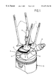
- FIG. 1 presents a perspective view of the layout of four gas exchange valves, ignition device, injection valve, and piston of a direct injection internal combustion engine in a simplified presentation;
- FIG. 2 a top view of the piston of FIG. 1;
- FIG. 3 a sectional view of the piston of FIG. 2 along line III—III;
- FIG. 1 The internal combustion engine claimed for the invention is shown by FIG. 1 to be provided with two intake valves per cylinder mounted side by side. These two intake valves 1 are situated on the intake side of a cylinder (not shown) and two exhaust valves 2 , also mounted side by side, are mounted on the exhaust side of the cylinder.
- the internal combustion engine has an ignition device 3 mounted concentrically with the axis of the cylinder.
- One injection valve 4 is also provided per cylinder, which valve is mounted between the two intake valves 1 and the section of the cylinder wall adjacent to both intake valves 1 .
- the piston 5 mounted in the cylinder of the internal combustion engine has a combustion chamber trough 6 which is mounted opposite the axis of the cylinder noticeably displaced toward the side of the two exhaust valves 2 and has a steep boundary wall 7 on the intake side and a gently sloping boundary wall 8 on the exhaust side.
- the width of the combustion chamber trough 6 is about two-thirds the diameter of the piston 5 and the center Z or volume center of gravity of the combustion chamber trough 6 is positioned approximately one-third of the diameter of the piston 5 from the edge of the piston 5 on the exhaust side of the latter and approximately one-sixth the diameter of the piston 5 from the axis of the cylinder.
- the fresh air flowing into the cylinder through the two intake valves 1 forms a tumble flow S inside the combustion chamber. This is enhanced if the two intake valves 1 are spaced a maximum distance from each other. In addition, maximum distance between the two intake valves 2 facilitates positioning of the injection valve 4 .
- the tumble flow may be generated inside the combustion chamber trough by flow control means mounted in the intake duct.
- Fresh air tumble flow S moves over the boundary wall 8 on the exhaust side into the combustion chamber trough 6 and, on emerging from the combustion chamber trough 6 , is deflected on the boundary wall 7 toward the ignition device 3 . Since the center Z of the combustion chamber trough 6 is positioned opposite the axis of the cylinder so as to be displaced toward the exhaust side and the boundary wall 7 of the combustion chamber trough 6 is mounted below the ignition device 3 , mixture preparation is especially favored in that the mixture moves directly toward the ignition device 3 .
- the two intake valves 1 are positioned parallel to each other and are mounted so as to be tilted at an angle, one toward the ignition device 3 and the other toward the axis of the cylinder.
- the two exhaust valves 2 are also positioned parallel to each other and are mounted so as to be tilted at an angle toward the axis of the cylinder in the direction opposite that of the intake valves 1 .
- the injection valve 4 of the internal combustion engine is mounted so as to be tilted toward the axis of the cylinder, the angle of inclination ⁇ of the injection valve 4 being approximately 30 to 80 degrees. As a result, the injection valve 4 is inclined toward the axis of the cylinder at an angle steeper than that of the adjacent intake valves 1 .
- the injection valve 4 injects fuel into the combustion chamber trough 6 during the compression stroke, at a crankshaft angle of approximately 120 to 20 degrees, before the piston 5 reaches the top dead center, in advance of the fresh air tumble flow deflected by the boundary wall 7 on the intake side.
- the fresh air tumble flow S ensures that the fuel stream K injected will be stabilized in an ignitable charge mist near the injection valve 4 inside the combustion chamber trough 6 and will be delivered to the ignition device 3 by further compression movement of the piston 5 , so that the ignitable portion of the mixture mist can be reached by an ignition spark of the ignition device 3 mounted coaxially in the cylinder.
Landscapes
- Engineering & Computer Science (AREA)
- Chemical & Material Sciences (AREA)
- Combustion & Propulsion (AREA)
- Mechanical Engineering (AREA)
- General Engineering & Computer Science (AREA)
- Combustion Methods Of Internal-Combustion Engines (AREA)
- Fuel-Injection Apparatus (AREA)
Applications Claiming Priority (3)
| Application Number | Priority Date | Filing Date | Title |
|---|---|---|---|
| DE19856016 | 1998-12-04 | ||
| DE19856016A DE19856016A1 (de) | 1998-12-04 | 1998-12-04 | Direkteinspritzende Brennkraftmaschine |
| PCT/EP1999/009311 WO2000034633A1 (de) | 1998-12-04 | 1999-12-01 | Direkteinspritzende brennkraftmaschine |
Publications (1)
| Publication Number | Publication Date |
|---|---|
| US6571764B1 true US6571764B1 (en) | 2003-06-03 |
Family
ID=7889996
Family Applications (1)
| Application Number | Title | Priority Date | Filing Date |
|---|---|---|---|
| US09/857,508 Expired - Lifetime US6571764B1 (en) | 1998-12-04 | 1999-12-01 | Direct injection internal combustion engine |
Country Status (5)
| Country | Link |
|---|---|
| US (1) | US6571764B1 (de) |
| EP (1) | EP1135583B1 (de) |
| JP (1) | JP2002531763A (de) |
| DE (2) | DE19856016A1 (de) |
| WO (1) | WO2000034633A1 (de) |
Cited By (1)
| Publication number | Priority date | Publication date | Assignee | Title |
|---|---|---|---|---|
| US20050247292A1 (en) * | 2004-05-10 | 2005-11-10 | Halsmer John P | Integrated fuel supply system for internal combustion engine |
Families Citing this family (1)
| Publication number | Priority date | Publication date | Assignee | Title |
|---|---|---|---|---|
| DE10304168A1 (de) * | 2003-02-03 | 2004-08-05 | Bayerische Motoren Werke Ag | Hubkolben-Brennkraftmaschine mit Benzin-Direkteinspritzung |
Citations (13)
| Publication number | Priority date | Publication date | Assignee | Title |
|---|---|---|---|---|
| DE3904760A1 (de) | 1988-02-26 | 1989-10-05 | Toyota Motor Co Ltd | Otto-brennkraftmaschine mit direkteinspritzung |
| US5127379A (en) | 1990-06-26 | 1992-07-07 | Toyota Jidosha Kabushiki Kaisha | Internal combustion engine |
| US5170759A (en) | 1990-12-17 | 1992-12-15 | Toyota Jidosha Kabushiki Kaisha | Fuel injection control device for an internal combustion engine |
| US5215053A (en) | 1990-12-19 | 1993-06-01 | Toyota Jidosha Kabushiki Kaisha | Fuel injection control device for an internal combustion engine |
| JPH09105330A (ja) | 1995-10-11 | 1997-04-22 | Daihatsu Motor Co Ltd | 四弁式内燃機関 |
| DE19713028A1 (de) | 1996-04-01 | 1997-10-30 | Avl List Gmbh | Viertakt-Brennkraftmaschine mit Fremdzündung |
| JPH1017659A (ja) | 1996-07-05 | 1998-01-20 | Toray Ind Inc | 液晶ポリエステルの製造方法 |
| JPH1031797A (ja) | 1996-07-16 | 1998-02-03 | Mitsubishi Precision Co Ltd | 駐車場における車両の特定方法及びそのシステム並びに駐車料金計算方法及びそのシステム |
| EP0824185A2 (de) | 1996-08-12 | 1998-02-18 | Mazda Motor Corporation | Fremdgezündeter Verbrennungsmotor mit Direkteinspritzung |
| DE19741380A1 (de) | 1996-09-20 | 1998-03-26 | Fev Motorentech Gmbh & Co Kg | Hubkolbenbrennkraftmaschine mit Kraftstoffdirekteinspritzung über einen einlaßseitig angeordneten Injektor |
| JPH113012A (ja) | 1997-06-12 | 1999-01-06 | Kyocera Corp | 画像形成装置 |
| DE19809066A1 (de) | 1998-03-04 | 1999-09-09 | Audi Ag | Direkteinspritzende Brennkraftmaschine |
| WO1999045249A1 (de) | 1998-03-04 | 1999-09-10 | Audi Ag | Direkteinspritzende brennkraftmaschine |
-
1998
- 1998-12-04 DE DE19856016A patent/DE19856016A1/de not_active Withdrawn
-
1999
- 1999-12-01 JP JP2000587057A patent/JP2002531763A/ja active Pending
- 1999-12-01 EP EP99958142A patent/EP1135583B1/de not_active Expired - Lifetime
- 1999-12-01 US US09/857,508 patent/US6571764B1/en not_active Expired - Lifetime
- 1999-12-01 WO PCT/EP1999/009311 patent/WO2000034633A1/de active IP Right Grant
- 1999-12-01 DE DE59911295T patent/DE59911295D1/de not_active Expired - Lifetime
Patent Citations (15)
| Publication number | Priority date | Publication date | Assignee | Title |
|---|---|---|---|---|
| DE3904760A1 (de) | 1988-02-26 | 1989-10-05 | Toyota Motor Co Ltd | Otto-brennkraftmaschine mit direkteinspritzung |
| US4920937A (en) | 1988-02-26 | 1990-05-01 | Toyota Jidosha Kabushiki Kaisha | Direct fuel injection type spark ignition internal combustion engine having a squish flow for assisting fuel evaporation |
| US5127379A (en) | 1990-06-26 | 1992-07-07 | Toyota Jidosha Kabushiki Kaisha | Internal combustion engine |
| US5170759A (en) | 1990-12-17 | 1992-12-15 | Toyota Jidosha Kabushiki Kaisha | Fuel injection control device for an internal combustion engine |
| US5215053A (en) | 1990-12-19 | 1993-06-01 | Toyota Jidosha Kabushiki Kaisha | Fuel injection control device for an internal combustion engine |
| JPH09105330A (ja) | 1995-10-11 | 1997-04-22 | Daihatsu Motor Co Ltd | 四弁式内燃機関 |
| DE19713028A1 (de) | 1996-04-01 | 1997-10-30 | Avl List Gmbh | Viertakt-Brennkraftmaschine mit Fremdzündung |
| JPH1017659A (ja) | 1996-07-05 | 1998-01-20 | Toray Ind Inc | 液晶ポリエステルの製造方法 |
| JPH1031797A (ja) | 1996-07-16 | 1998-02-03 | Mitsubishi Precision Co Ltd | 駐車場における車両の特定方法及びそのシステム並びに駐車料金計算方法及びそのシステム |
| EP0824185A2 (de) | 1996-08-12 | 1998-02-18 | Mazda Motor Corporation | Fremdgezündeter Verbrennungsmotor mit Direkteinspritzung |
| DE19741380A1 (de) | 1996-09-20 | 1998-03-26 | Fev Motorentech Gmbh & Co Kg | Hubkolbenbrennkraftmaschine mit Kraftstoffdirekteinspritzung über einen einlaßseitig angeordneten Injektor |
| JPH113012A (ja) | 1997-06-12 | 1999-01-06 | Kyocera Corp | 画像形成装置 |
| DE19809066A1 (de) | 1998-03-04 | 1999-09-09 | Audi Ag | Direkteinspritzende Brennkraftmaschine |
| WO1999045249A1 (de) | 1998-03-04 | 1999-09-10 | Audi Ag | Direkteinspritzende brennkraftmaschine |
| US6378490B1 (en) | 1998-03-04 | 2002-04-30 | Audi Ag | Direct injection internal combustion engine |
Cited By (2)
| Publication number | Priority date | Publication date | Assignee | Title |
|---|---|---|---|---|
| US20050247292A1 (en) * | 2004-05-10 | 2005-11-10 | Halsmer John P | Integrated fuel supply system for internal combustion engine |
| US7290531B2 (en) * | 2004-05-10 | 2007-11-06 | John Peter Halsmer | Integrated fuel supply system for internal combustion engine |
Also Published As
| Publication number | Publication date |
|---|---|
| DE19856016A1 (de) | 2000-06-08 |
| JP2002531763A (ja) | 2002-09-24 |
| EP1135583B1 (de) | 2004-12-15 |
| DE59911295D1 (de) | 2005-01-20 |
| WO2000034633A1 (de) | 2000-06-15 |
| EP1135583A1 (de) | 2001-09-26 |
Similar Documents
| Publication | Publication Date | Title |
|---|---|---|
| US6378490B1 (en) | Direct injection internal combustion engine | |
| US7347181B2 (en) | Direct injection spark ignition engine | |
| US7395806B2 (en) | Reciprocating internal-combustion engine with direct fuel injection by means of an injector arranged on the intake side | |
| US6705275B2 (en) | Incylinder direct injection spark ignition engine | |
| US6378486B1 (en) | Four-stroke internal combustion engine with direct injection | |
| US20030116107A1 (en) | Two-stroke internal combustion engine with crankcase scavenging | |
| EP0691470B1 (de) | Brennkraftmaschine und Verfahren zur Luft-Kraftstoffgemischbildung dafür | |
| US5284111A (en) | Two-state internal combustion engine | |
| US5062395A (en) | Two-stroke internal combustion engine | |
| JP3926989B2 (ja) | 筒内噴射式火花点火エンジンの制御装置 | |
| CN107620661B (zh) | 内燃发动机和用于操作所述类型的内燃发动机的方法 | |
| US6799550B2 (en) | Spark-ignition engine having direct fuel injection | |
| US3572298A (en) | Stratified charge engine | |
| US20090139485A1 (en) | Direct injection two-stroke engine | |
| US20020179026A1 (en) | Two-stroke internal combustion engine with crankcase scavenging | |
| EP1098074A2 (de) | Fremdgezündete Direkteinspritzbrennkraftmaschine | |
| US6571764B1 (en) | Direct injection internal combustion engine | |
| JP2003524729A (ja) | 吸気側に配置した噴射装置によって燃料を噴射する往復ピストン式内燃機関 | |
| US7152572B2 (en) | Internal combustion engine | |
| US4442809A (en) | Combustion chamber of an internal combustion engine with an accumulation chamber | |
| EP0751286B1 (de) | Brennkraftmaschine mit einer Kraftstoffzufuhreinrichtung | |
| US20010029912A1 (en) | Two-stroke internal combustion engine with crankcase scavenging | |
| US4325333A (en) | Internal combustion engine equipped with an auxiliary combustion chamber | |
| JPH0518244A (ja) | 筒内噴射式内燃機関 | |
| JPH0510137A (ja) | 筒内噴射式内燃機関 |
Legal Events
| Date | Code | Title | Description |
|---|---|---|---|
| AS | Assignment |
Owner name: AUDI AG, GERMANY Free format text: ASSIGNMENT OF ASSIGNORS INTEREST;ASSIGNORS:OTTOWITZ, ALFRED;WURMS, RAINER;BUDACK, RALF;AND OTHERS;REEL/FRAME:012057/0730;SIGNING DATES FROM 20010502 TO 20010504 |
|
| STCF | Information on status: patent grant |
Free format text: PATENTED CASE |
|
| FPAY | Fee payment |
Year of fee payment: 4 |
|
| FPAY | Fee payment |
Year of fee payment: 8 |
|
| FPAY | Fee payment |
Year of fee payment: 12 |