US64471A - Stephen ballard - Google Patents
Stephen ballard Download PDFInfo
- Publication number
- US64471A US64471A US64471DA US64471A US 64471 A US64471 A US 64471A US 64471D A US64471D A US 64471DA US 64471 A US64471 A US 64471A
- Authority
- US
- United States
- Prior art keywords
- churn
- shaft
- dasher
- attached
- arms
- Prior art date
- Legal status (The legal status is an assumption and is not a legal conclusion. Google has not performed a legal analysis and makes no representation as to the accuracy of the status listed.)
- Expired - Lifetime
Links
- 239000000203 mixture Substances 0.000 description 14
- 210000004080 Milk Anatomy 0.000 description 12
- 239000006071 cream Substances 0.000 description 12
- 235000013336 milk Nutrition 0.000 description 12
- 239000008267 milk Substances 0.000 description 12
- 235000014121 butter Nutrition 0.000 description 6
- 230000015572 biosynthetic process Effects 0.000 description 4
- 238000005755 formation reaction Methods 0.000 description 4
- 210000002832 Shoulder Anatomy 0.000 description 2
- 230000023298 conjugation with cellular fusion Effects 0.000 description 2
- 230000013011 mating Effects 0.000 description 2
- 230000001737 promoting Effects 0.000 description 2
- 230000021037 unidirectional conjugation Effects 0.000 description 2
Images

Classifications
-
- B—PERFORMING OPERATIONS; TRANSPORTING
- B01—PHYSICAL OR CHEMICAL PROCESSES OR APPARATUS IN GENERAL
- B01F—MIXING, e.g. DISSOLVING, EMULSIFYING OR DISPERSING
- B01F27/00—Mixers with rotary stirring devices in fixed receptacles; Kneaders
- B01F27/05—Stirrers
- B01F27/11—Stirrers characterised by the configuration of the stirrers
- B01F27/112—Stirrers characterised by the configuration of the stirrers with arms, paddles, vanes or blades
- B01F27/1125—Stirrers characterised by the configuration of the stirrers with arms, paddles, vanes or blades with vanes or blades extending parallel or oblique to the stirrer axis
- B01F27/11251—Stirrers characterised by the configuration of the stirrers with arms, paddles, vanes or blades with vanes or blades extending parallel or oblique to the stirrer axis having holes in the surface
Definitions
- Figure 2 is a horizontal section of the same, taken through the line y y, tig. 1.
- Figure i is a detail sectional view, taken through the line z z, fig. 1.
- Figure is an under side View of thc lid or cover of the churn.
- My invention has for its object to furnish an improved churn by means of which the churning may be done very rapidly and thoroughly; and it consists, first, in the combination of knives and hinged or jointed arms with the dasher-shaft; second, in the combination of a circular dasher with the dasher-shaft; third, in the combination of the side-screens with the sides ofthe churn; fourth, in the combination of the frame and gearing with the sides of thc churn and with the lid or cover, as hereinafter more fully described.
- A is the body of the churn, which'may he cylindrical, tapering, or barrel-shaped, as may be desired.
- D is'thc screen, which is formed of a narrow part, bl, and a wider part, b2. The edge of the narrow part b1 is made to conform to the shape of the side' of the churn against which it fits, but the other edge is vertical, and to it is securely attached the broader part 6,2, so that the part b may be parallel with the dasher-shaft.
- This screen is perforated with numerous holes, and as the dasherv revolves the milk or cream is driven by it into the pockets formed by the screens B, and is compelled to find its way out through the holes in said screens, materially increasing the rapidityof the formation of the butter.
- the lower ends of the screens B rest in grooves formed in the bottom al of the churn, or against blocks attached to said bottom. Their upper ends rest against blocks C, attached to the sides of the churn, and they are still further supported by their upper ends fitting into grooves formed in the lid or cover D, as shown in fig. 5.
- the lid or cover D is made in two' parts for convenience in putting it on and taking it olf, and its edges are notched, as shown in tigs. 1
- the arms c and c2 are made of such a form as to t upon the outer side of the churn A, where they are held in place by clasps or keepers .1?, attached to the said sides.
- .e3 is the cross-bar of the frame, in which the crank-shaft G has its bearings. Upon the crank-shaft G is placed a bevel gear-wheel, H, which meshes into a smaller gear-Wheel, I, attached to the dasher-shaft J, as shown in Iig. 1.
- the dasher-shaft J is pvotcd at its upper-end in a'socket attached to or formed in-the under side of the cross-bar e3 of the frame E, and at its lower end, in a socket formed in or attached to the bottom a1 of the churn A, as seen in fig. 1.
- a circular plate or disk, K To the shaft J, immediately below the gear-wheel I, is attached a circular plate or disk, K, which catches any dirt that may fall from the gearing and prevents it from finding lts way into the churn through the hole in the lid D.
- L is a circular dasher, having notches formed in 'its edge, one of which extends inward a little past the centre, and terminates in a square notch, into which ts a squared part of the dasher-shaft J, in which position the dashcr L is held by a catch or button, M, pivoted to one side of the said dasher and held in place hy a pin, as shown in figs. 1 and 2.
- the dasher-shaft J is squared at several points for thel reception of the dashcr L, so that the position of the dasher may be adjusted according to the amount of cream or milk in the churn.
- N and O are arms attached to the'dasher shaft .l below the dashcr. Each end of these arms is jointed, as shown in figs. l and 3, so that when the shaft J is revolved in one direction the said arms may pass through the milk or cream extended, hut when revolved in the other direction the end parts of the arms may foldv hack.
- the arms N and O are attached to the shaft at right angles to each other, as shown in figs. I and 3.
- I7 are knives attached to the shaft J to interrupt the currents of milk 01' cream forced up and clown by the arms N and O, thereby increasing the agitation of' tlie said milk or cream, and promoting the formation of the butter.
Landscapes
- Chemical & Material Sciences (AREA)
- Chemical Kinetics & Catalysis (AREA)
- Dairy Products (AREA)
Description
s. BALLARD, Sr.
Churn.
Patented May 7. 1867.
N. PETER. PHOTO-UTHOGRAPMEFL WASHNGTON. D C,
@uiten Gp trs @strut ffir.
Lefera Patent No. 64,471, dated lay 7,1867.
IMPROVEMENT IN CHURNS.
@tr Srlganlc ninna tu iu ilgese .Enters 'utnit 1mb mating gmt nf tige sami.
IO ALL WIIOM IT MAY CONCERN:
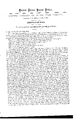
Be it known that I, STEPHEN BALLARD, of Sullivan, in the county of Sullivan, and State of Indiana, have invented a new and useful Improvement in Churns; and I do hereby declare that the following is a full, clear, and exact description thereof, which will enable others skilled in the art to make and use the same, reference boing had to the accompanying drawings, forming part of this specification, in which--4 Figure l is a vertical central section of my improved churn, taken through the line :c zr, fig. 2.
Figure 2 is a horizontal section of the same, taken through the line y y, tig. 1.
Figure i is a detail sectional view, taken through the line z z, fig. 1.
Figure l= is a perspective view of the side screen.
Figure is an under side View of thc lid or cover of the churn.
Similar letters of reference indicate like parts.
My invention has for its object to furnish an improved churn by means of which the churning may be done very rapidly and thoroughly; and it consists, first, in the combination of knives and hinged or jointed arms with the dasher-shaft; second, in the combination of a circular dasher with the dasher-shaft; third, in the combination of the side-screens with the sides ofthe churn; fourth, in the combination of the frame and gearing with the sides of thc churn and with the lid or cover, as hereinafter more fully described.
A is the body of the churn, which'may he cylindrical, tapering, or barrel-shaped, as may be desired. D is'thc screen, which is formed of a narrow part, bl, and a wider part, b2. The edge of the narrow part b1 is made to conform to the shape of the side' of the churn against which it fits, but the other edge is vertical, and to it is securely attached the broader part 6,2, so that the part b may be parallel with the dasher-shaft. This screen is perforated with numerous holes, and as the dasherv revolves the milk or cream is driven by it into the pockets formed by the screens B, and is compelled to find its way out through the holes in said screens, materially increasing the rapidityof the formation of the butter. The lower ends of the screens B rest in grooves formed in the bottom al of the churn, or against blocks attached to said bottom. Their upper ends rest against blocks C, attached to the sides of the churn, and they are still further supported by their upper ends fitting into grooves formed in the lid or cover D, as shown in fig. 5. The lid or cover D is made in two' parts for convenience in putting it on and taking it olf, and its edges are notched, as shown in tigs. 1
and 5, into which notches fit shoulders `formed on the arms c1 and e'z of the frame E,.which holds the cover securely in place. The arms c and c2 are made of such a form as to t upon the outer side of the churn A, where they are held in place by clasps or keepers .1?, attached to the said sides. .e3 is the cross-bar of the frame, in which the crank-shaft G has its bearings. Upon the crank-shaft G is placed a bevel gear-wheel, H, which meshes into a smaller gear-Wheel, I, attached to the dasher-shaft J, as shown in Iig. 1. The dasher-shaft J is pvotcd at its upper-end in a'socket attached to or formed in-the under side of the cross-bar e3 of the frame E, and at its lower end, in a socket formed in or attached to the bottom a1 of the churn A, as seen in fig. 1. To the shaft J, immediately below the gear-wheel I, is attached a circular plate or disk, K, which catches any dirt that may fall from the gearing and prevents it from finding lts way into the churn through the hole in the lid D. L is a circular dasher, having notches formed in 'its edge, one of which extends inward a little past the centre, and terminates in a square notch, into which ts a squared part of the dasher-shaft J, in which position the dashcr L is held by a catch or button, M, pivoted to one side of the said dasher and held in place hy a pin, as shown in figs. 1 and 2. The dasher-shaft J is squared at several points for thel reception of the dashcr L, so that the position of the dasher may be adjusted according to the amount of cream or milk in the churn. l is a paddle projecting upward from the upper surface of the dasher L to gather the butter when the churning is about completed, and F are paddles projecting downward from the lower side of the said vdashcr l., for the purpose of aiding in thoagitation of the milk or cream. N and O are arms attached to the'dasher shaft .l below the dashcr. Each end of these arms is jointed, as shown in figs. l and 3, so that when the shaft J is revolved in one direction the said arms may pass through the milk or cream extended, hut when revolved in the other direction the end parts of the arms may foldv hack. The arms N and O are attached to the shaft at right angles to each other, as shown in figs. I and 3. I7 are knives attached to the shaft J to interrupt the currents of milk 01' cream forced up and clown by the arms N and O, thereby increasing the agitation of' tlie said milk or cream, and promoting the formation of the butter.
I cla-im as new, and desire to secure by Letters Patent- 1. The combination of the knives P, and hinged or jointed arms N and O, with tlie (bisher-shaft J, substantially as described and for the purpose set forth.
2. The combination of the Circular claslier L, constructed n.3 described with the daslier-slmft J, substantially as. and for the purpose set forth. 4
3. The combination ofthe frame E and gearing G H I with each otllerhzmil with tllc Sides nml top or cover D ef the churn A, substantially as described and for the purpose set forth.
' STEPHEN BALLARD, SR.
Witnesses:
J. G. RILEY, EZEKILL RILEY.
Publications (1)
| Publication Number | Publication Date |
|---|---|
| US64471A true US64471A (en) | 1867-05-07 |
Family
ID=2134002
Family Applications (1)
| Application Number | Title | Priority Date | Filing Date |
|---|---|---|---|
| US64471D Expired - Lifetime US64471A (en) | Stephen ballard |
Country Status (1)
| Country | Link |
|---|---|
| US (1) | US64471A (en) |
Cited By (2)
| Publication number | Priority date | Publication date | Assignee | Title |
|---|---|---|---|---|
| US20070050711A1 (en) * | 2000-05-08 | 2007-03-01 | Walker Jay S | Method and system for providing a link in an electronic file being presented to a user |
| US20080151687A1 (en) * | 2006-12-21 | 2008-06-26 | Lee Martin Adelsberg | Method for minimizing erosion of refractory metal vessels in a glass making system |
-
0
- US US64471D patent/US64471A/en not_active Expired - Lifetime
Cited By (6)
| Publication number | Priority date | Publication date | Assignee | Title |
|---|---|---|---|---|
| US20070050711A1 (en) * | 2000-05-08 | 2007-03-01 | Walker Jay S | Method and system for providing a link in an electronic file being presented to a user |
| US20070073774A1 (en) * | 2000-05-08 | 2007-03-29 | Walker Jay S | Method and system for providing a link in an electronic file being presented to a user |
| US20070073773A1 (en) * | 2000-05-08 | 2007-03-29 | Walker Jay S | Method and system for providing a link in an electronic file being presented to a user |
| US20080151687A1 (en) * | 2006-12-21 | 2008-06-26 | Lee Martin Adelsberg | Method for minimizing erosion of refractory metal vessels in a glass making system |
| US8256951B2 (en) * | 2006-12-21 | 2012-09-04 | Corning Incorporated | Stirrers for minimizing erosion of refractory metal vessels in a glass making system |
| US8485717B2 (en) | 2006-12-21 | 2013-07-16 | Corning Incorporated | Stirrers for minimizing erosion of refractory metal vessels in a glass making system |
Similar Documents
| Publication | Publication Date | Title |
|---|---|---|
| US64471A (en) | Stephen ballard | |
| US60097A (en) | Improvement in ghoshs | |
| US230295A (en) | Churn-dasher | |
| US66949A (en) | of owatonna | |
| US69653A (en) | Improvement in churns | |
| US61691A (en) | Robert stanley | |
| US75842A (en) | Improvement in ohuens | |
| US166181A (en) | Improvement in rotary churns | |
| US67964A (en) | eggebt | |
| US76484A (en) | To all whom it may concern | |
| US58059A (en) | Improvement in churns | |
| US96604A (en) | Improvement in churns | |
| US75539A (en) | Improvement in churns | |
| US59282A (en) | Improvement in churns | |
| US69624A (en) | Improvement in churns | |
| US51073A (en) | Improvement in churns | |
| US70249A (en) | Improvement in churns | |
| US69934A (en) | Improvement in ohuens | |
| US70229A (en) | Improvement in churn-dashers | |
| US55287A (en) | Improvement in churns | |
| US81615A (en) | John fassauer | |
| US64348A (en) | myers | |
| US76185A (en) | Efeas t | |
| US187933A (en) | Improvement in churns | |
| US119870A (en) | Improvement in churns |