US6437509B1 - Electrode for discharge lamps - Google Patents
Electrode for discharge lamps Download PDFInfo
- Publication number
- US6437509B1 US6437509B1 US09/581,197 US58119700A US6437509B1 US 6437509 B1 US6437509 B1 US 6437509B1 US 58119700 A US58119700 A US 58119700A US 6437509 B1 US6437509 B1 US 6437509B1
- Authority
- US
- United States
- Prior art keywords
- electrode
- pin
- solid body
- electrode according
- laser
- Prior art date
- Legal status (The legal status is an assumption and is not a legal conclusion. Google has not performed a legal analysis and makes no representation as to the accuracy of the status listed.)
- Expired - Lifetime
Links
Images


Classifications
-
- H—ELECTRICITY
- H01—ELECTRIC ELEMENTS
- H01J—ELECTRIC DISCHARGE TUBES OR DISCHARGE LAMPS
- H01J61/00—Gas-discharge or vapour-discharge lamps
- H01J61/02—Details
- H01J61/04—Electrodes; Screens; Shields
- H01J61/06—Main electrodes
- H01J61/073—Main electrodes for high-pressure discharge lamps
- H01J61/0732—Main electrodes for high-pressure discharge lamps characterised by the construction of the electrode
-
- H—ELECTRICITY
- H01—ELECTRIC ELEMENTS
- H01J—ELECTRIC DISCHARGE TUBES OR DISCHARGE LAMPS
- H01J61/00—Gas-discharge or vapour-discharge lamps
- H01J61/02—Details
- H01J61/04—Electrodes; Screens; Shields
- H01J61/06—Main electrodes
- H01J61/067—Main electrodes for low-pressure discharge lamps
- H01J61/0672—Main electrodes for low-pressure discharge lamps characterised by the construction of the electrode
-
- H—ELECTRICITY
- H01—ELECTRIC ELEMENTS
- H01J—ELECTRIC DISCHARGE TUBES OR DISCHARGE LAMPS
- H01J61/00—Gas-discharge or vapour-discharge lamps
- H01J61/02—Details
- H01J61/04—Electrodes; Screens; Shields
- H01J61/06—Main electrodes
- H01J61/067—Main electrodes for low-pressure discharge lamps
- H01J61/0675—Main electrodes for low-pressure discharge lamps characterised by the material of the electrode
-
- H—ELECTRICITY
- H01—ELECTRIC ELEMENTS
- H01J—ELECTRIC DISCHARGE TUBES OR DISCHARGE LAMPS
- H01J61/00—Gas-discharge or vapour-discharge lamps
- H01J61/02—Details
- H01J61/04—Electrodes; Screens; Shields
- H01J61/06—Main electrodes
- H01J61/073—Main electrodes for high-pressure discharge lamps
- H01J61/0735—Main electrodes for high-pressure discharge lamps characterised by the material of the electrode
Definitions
- the invention relates to an electrode for discharge lamps having a pin at least partially surrounded by a solid body.
- Electrodes of the type mentioned in the introduction are used in discharge lamps in order to release or receive electrons during a gas discharge.
- the electrodes each contain a pin, at the free end of which electrons either emerge from the pin or enter it at this end, wherein the pin is generally partially surrounded by a cooling body in the proximity of its free end, which cooling body is usually formed from a wire wound around the pin. It has been shown that both the application of such a cooling body formed from a wound wire on the pin and also a robust attachment of the cooling body to the pin can only be achieved at a high technical cost, wherein the results with respect to a firm attachment of the cooling body to the pin are not satisfactory.
- this object is achieved in that the solid body is produced from a high-melting material.
- the solid body being formed from a high-melting material, that the solid body also holding the function of a cooling body can be produced as a solid block which can be firmly connected to the pin both by reason of is material composition and also its dimensions.
- the solid body is formed from a material which has a melting point above 1800° C.
- the solid body is preferably formed from tungsten.
- the solid body is preferably in the form of a cylinder in which an axial bore is introduced.
- the axial bore is dimensioned in such a way that the pin of the electrode can be introduced into the bore.
- the solid body can be connected to the pin by a number of different methods to form a fixed unit as explained in more detail hereinunder.
- the bore is introduced into the cylinder by means of a laser, in particular a Nd:YAG laser.
- the solid body is composed of a plurality of partial solid bodies disposed one after the other. In this way it is achieved that particularly long electrode bodies in accordance with the invention can be produced which cannot be produced in a single-piece form by reason of the limited penetration depth of a laser beam.
- the solid body-side end of the pin is welded to the end of the solid body surrounding it.
- This welding is preferably carried out by means of a laser, in particular a Nd:YAG or CO 2 laser, and brings about the effect that the common end of the pin and of the solid body surrounding it is formed in the manner of a convex cap, of which the edge region forms a transition to the solid body.
- a cap formed in this way for the electrode in accordance with the invention comprises the advantage that it is particularly effective and resistant to wear.
- the solid body is provided with at least one transverse bore. If a transverse bore of this type is introduced into a solid body before an axial bore is introduced it permits removal to the outside of the vaporisation particles which arise when the axial bore is introduced by means of the laser. The formation of an axial bore by laser beams is thus particularly effective by reason of the rapid escape of the vapour particles thus effected from the region penetrated by laser beams. Furthermore, by means of the introduction of a transverse bore into a solid body, the possibility is created of welding the solid body to the pin at an additional fixing point than just the cap.
- the welding of these fixing points is preferably also carried out by laser beams.
- the introduction of transverse bores into the solid body also makes it possible to introduce or deposit emission pastes into the transverse bores.
- Emission pastes are generally materials which promote an electron emission of the electrode.
- the solid body therefore fulfills the function of increased electron emission in addition to the cooling function.
- the emission paste contains, for example thorium oxide.
- the bore of the solid body of the electrode in accordance with the invention preferably comprises an inner diameter which is larger than the diameter of the pin, wherein the intermediate space between the solid body and the pin is filled with a melt.
- the melt preferably contains molybdenum. It is also possible, however, to consider tantalum, niobium, titanium or platinum. In this way a robust connection between the solid body and the pin is created in each case.
- the solid body can be shrunk mechanically by means of a plurality of stamps acting inwardly from the outside, to such an extent that it comes into a mechanically firm connection with the pin.
- the solid body is preferably welded to the pin at one or more fixing points, wherein the corresponding welding process is preferably achieved by laser radiation.
- a firm mechanical connection between the solid body and the pin is also made possible by a process for directly welding the solid body to the pin, carried out, in particular, at a plurality of fixing points, in the region of common outer contact edges or in the region of transverse bores.
- FIG. 1 illustrates a conventional discharge lamp in a transverse cross-sectional view
- FIG. 2 illustrates a conventional electrode in a side view
- FIG. 3 illustrates a preferred embodiment of the electrode in accordance with the invention, in a transverse cross-sectional view
- FIG. 4 illustrates a further preferred embodiment of the electrode in accordance with the invention in a transverse cross-sectional view
- FIG. 5 illustrates a further preferred embodiment of the electrode in accordance with the invention in a transverse cross-sectional view
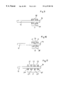
- FIG. 6 illustrates a schematic view of a device for stamping an electrode body in accordance with the invention in a view from above;
- FIG. 7 illustrates a further preferred embodiment of the electrode body in accordance with the invention in a view from the front, after stamping by means of the stamping device shown in FIG. 6;
- FIG. 8 illustrates a further preferred embodiment of the electrode body in accordance with the invention in a transverse cross-sectional view
- FIG. 9 illustrates a further preferred embodiment of the electrode body in accordance with the invention in a transverse cross sectional view
- FIG. 10 illustrates a further preferred embodiment of the electrode body in accordance with the invention in a transverse cross-sectional view
- FIG. 11 illustrates a further preferred embodiment of the electrode body in accordance with the invention in a transverse cross-sectional view.
- two electrodes 11 , 11 ′ are disposed inside a silica glass bulb 12 in such a way that in each case one end, which is also designated as electrode pin 13 , 13 ′, is welded in the glass bulb 12 .
- the electrodes 11 , 11 ′ are disposed opposite each other at opposite ends of the bulb 12 .
- the electrode pins 13 , 13 ′ are connected by molybdenum foils 14 , 14 ′ to molybdenums pins 15 , 15 ′ which are each provided for connection to the power supply.
- the molybdenum foils 14 , 14 ′ thus act as power supply elements to the electrode pins 13 , 13 ′ inside the glass bulb.
- the electrodes 11 , 11 ′ each also comprise a free electrode end 16 , 16 ′ also referred to as a “tip”, wherein between the electrode ends 16 , 16 ′ an electron exchange can take place in such a way that the respective electrode end emits electrons and the other electrode end forms an input for electrons.
- the electrodes 11 , 11 ′ are each surrounded in the region of their ends 16 , 16 ′ by an electrode body or cooling body 17 , 17 ′.
- FIG. 2 a conventional electrode 11 as used in a discharge bulb 12 in accordance with FIG. 1 is illustrated in a side view.
- the electrode body or cooling body 17 is formed from a wire wound around the electrode pin 13 , the ends 17 a and 17 b of which are free. As shown in the Figure, the wire can be wound in two layers in respectively different directions.
- a hollow-cylindrical solid body 17 is provided as the electrode body or cooling body around the relevant part 18 of the electrode pin 13 instead of a wire winding 17 illustrated in FIG. 2 .
- the electrode body 17 is produced overall as a solid block of a solid body which is formed from a high-melting material.
- the electrode 11 illustrated in FIG. 3 comprises a free electrode end 16 .
- the electrode 11 in accordance with the invention illustrated in FIG. 4 designate like components as in the electrode illustrated in FIG. 3 .
- the electrode 11 illustrated in FIG. 4 comprises no separate electrode end 16 .
- the “flush” electrode end 16 a is welded to the electrode body 17 by laser so that an electrode end 16 b is formed, of which the diameter is formed as an outwardly directed half-sphere in contrast to the electrode end 16 illustrated in FIG. 3, and is enlarged to the diameter of the electrode body 17 .
- a half-spherical cap is formed, wherein the arc in the lamp in each case seeks the shortest path between the electrodes and in the case of caps formed as half-spheres always contacts the highest point thereof, whereas in the case of flat ends it can travel to and fro on the corresponding surface, which leads to an unsteady light.
- a particularly high level of consistency in the light intensity given out is therefore observed.
- a plurality of stamps 20 , 21 , 22 , 23 , 24 , 25 are disposed concentrically around an electrode 11 .
- the stamps 20 to 25 can be moved under high pressure in a reciprocal manner in the direction of the arrow by means of a mechanism, not illustrated, wherein the electrode 11 illustrated in transverse cross-section is disposed in the middle of the stamps 20 to 25 in such a way that the stamps 20 to 25 each lie against the electrode body 17 of the electrode 11 at substantially the same moment and then press the electrode body 17 in the direction of the electrode pin 18 , each applying the same force, wherein the electrode body 17 with the electrode pin 18 are pressed together to form a unit, with deformation both of the electrode body 17 and also of the electrode pin 18 , as shown in the case of a corresponding electrode 11 illustrated in transverse cross-section in FIG. 7 .
- the electrode body 17 is soldered or welded to the electrode pin 18 using tantalum as the soldering mass.
- the soldering or welding of electrode bodies 17 to the electrode pin 18 is an alternative process to the process illustrated in FIG. 6, for durably and firmly connecting an electrode body 17 to an electrode pin 18 .
- the bore in the solid body 17 comprises an inner diameter which is larger than the diameter of the pin 16 , wherein the intermediate space between the solid body 17 and the pin 16 is filled with a melt.
- the melt contains molybdenum.
- the electrode body 17 comprises transverse bores 20 , 20 ′.
- the electrode body 17 is welded to the electrode pin 13 in the transverse bores 20 , 20 ′ in order to comprise better adhesion to the electrode body 13 .
- the electrode body 17 is composed of a plurality of partial solids bodies 17 ′, 17 ′′, 17 ′′′ and 17 ′′′′ disposed one after the other. Between these partial solid bodies apertures 22 are provided. The dimensions of the apertures 22 can also be larger or smaller than shown in the Figure.
Landscapes
- Discharge Lamp (AREA)
- Manufacture Of Electron Tubes, Discharge Lamp Vessels, Lead-In Wires, And The Like (AREA)
Abstract
Description
Claims (15)
Applications Claiming Priority (3)
| Application Number | Priority Date | Filing Date | Title |
|---|---|---|---|
| DE19757152A DE19757152C2 (en) | 1997-12-20 | 1997-12-20 | Electrode for discharge lamps |
| DE19757152 | 1997-12-20 | ||
| PCT/DE1998/000624 WO1999033090A1 (en) | 1997-12-20 | 1998-03-04 | Electrode for discharge lamps |
Publications (1)
| Publication Number | Publication Date |
|---|---|
| US6437509B1 true US6437509B1 (en) | 2002-08-20 |
Family
ID=7852932
Family Applications (1)
| Application Number | Title | Priority Date | Filing Date |
|---|---|---|---|
| US09/581,197 Expired - Lifetime US6437509B1 (en) | 1997-12-20 | 1998-03-04 | Electrode for discharge lamps |
Country Status (6)
| Country | Link |
|---|---|
| US (1) | US6437509B1 (en) |
| EP (1) | EP1048052B1 (en) |
| JP (1) | JP2001527272A (en) |
| AT (1) | ATE268503T1 (en) |
| DE (2) | DE19757152C2 (en) |
| WO (1) | WO1999033090A1 (en) |
Cited By (7)
| Publication number | Priority date | Publication date | Assignee | Title |
|---|---|---|---|---|
| US20030087578A1 (en) * | 2001-07-04 | 2003-05-08 | Fuji Photo Film Co., Ltd. | Electrode producing method |
| EP1434252A2 (en) * | 2002-12-02 | 2004-06-30 | Patent -Treuhand-Gesellschaft für elektrische Glühlampen mbH | Metal halide lamp with ceramic discharge vessel, electrode system for such a lamp and manufacturing method of such a system |
| US20060055329A1 (en) * | 2004-09-10 | 2006-03-16 | Ushio Denki Kabushiki Kaisha | Extra-high pressure mercury lamp |
| US20060208635A1 (en) * | 2005-03-15 | 2006-09-21 | Lenef Alan L | Slotted electrode for high intensity discharge lamp |
| US20070159100A1 (en) * | 2003-12-22 | 2007-07-12 | Patent-Treuhand-Gesellschaft Fur Elektrische Gluhlampen Mbh | Electrode for a high-pressure discharge lamp |
| US20070182332A1 (en) * | 2003-05-26 | 2007-08-09 | Koninklijke Philips Electronics N.V. | Thorium-free electrode with improved color stability |
| US20110140601A1 (en) * | 2009-12-15 | 2011-06-16 | Osram Gesellschaft Mit Beschraenkter Haftung | Electrode structures for discharge lamps |
Citations (16)
| Publication number | Priority date | Publication date | Assignee | Title |
|---|---|---|---|---|
| US2477279A (en) | 1946-09-11 | 1949-07-26 | Hanovia Chemical & Mfg Co | Electrical discharge device |
| DE1187730B (en) | 1961-01-02 | 1965-02-25 | Patra Patent Treuhand | Electrode for gas and / or vapor discharge lamps |
| US3303377A (en) | 1962-08-17 | 1967-02-07 | Philips Corp | High pressure electric discharge tube |
| US4038579A (en) | 1973-01-11 | 1977-07-26 | U.S. Philips Corporation | Solder joint connection between lead-in conductor and electrode |
| US4340836A (en) | 1978-09-11 | 1982-07-20 | General Electric Company | Electrode for miniature high pressure metal halide lamp |
| US4628225A (en) | 1982-11-02 | 1986-12-09 | W. C. Heraeus Gmbh | Electrode for laser stimulation lamps |
| JPS62241253A (en) | 1986-04-10 | 1987-10-21 | Ushio Inc | Discharge lamp |
| JPS62241254A (en) | 1986-04-10 | 1987-10-21 | Ushio Inc | Discharge lamp |
| JPS62243235A (en) | 1986-04-16 | 1987-10-23 | Toshiba Corp | High pressure sodium lamp |
| JPS62249349A (en) | 1986-04-21 | 1987-10-30 | Toshiba Corp | High pressure sudium vapor lamp |
| JPS62249348A (en) | 1986-04-21 | 1987-10-30 | Toshiba Corp | High pressure sodium vapor lamp |
| JPH0652828A (en) | 1992-07-29 | 1994-02-25 | Toshiba Lighting & Technol Corp | Discharge lamp using sintered electrode |
| EP0639853A1 (en) | 1993-08-16 | 1995-02-22 | Patent-Treuhand-Gesellschaft für elektrische Glühlampen mbH | High-pressure discharge lamp with ceramic discharge vessel |
| US5532552A (en) | 1993-11-10 | 1996-07-02 | Patent-Treuhand-Gesellschaft F. Elektrische Gluehlampen Mbh | Metal-halide discharge lamp with ceramic discharge vessel, and method of its manufacture |
| EP0756312A2 (en) | 1995-07-26 | 1997-01-29 | Gesellschaft Für Wolfram-Industrie Mbh | Electrode with cooling element |
| JPH09231939A (en) | 1996-02-20 | 1997-09-05 | Tokyo Tungsten Co Ltd | High melting point metal electrode, its manufacture, and electrode for discharge lamp using it |
-
1997
- 1997-12-20 DE DE19757152A patent/DE19757152C2/en not_active Expired - Fee Related
-
1998
- 1998-03-04 EP EP98916838A patent/EP1048052B1/en not_active Expired - Lifetime
- 1998-03-04 AT AT98916838T patent/ATE268503T1/en active
- 1998-03-04 US US09/581,197 patent/US6437509B1/en not_active Expired - Lifetime
- 1998-03-04 WO PCT/DE1998/000624 patent/WO1999033090A1/en active IP Right Grant
- 1998-03-04 DE DE59811521T patent/DE59811521D1/en not_active Expired - Lifetime
- 1998-03-04 JP JP2000525908A patent/JP2001527272A/en active Pending
Patent Citations (17)
| Publication number | Priority date | Publication date | Assignee | Title |
|---|---|---|---|---|
| US2477279A (en) | 1946-09-11 | 1949-07-26 | Hanovia Chemical & Mfg Co | Electrical discharge device |
| DE1187730B (en) | 1961-01-02 | 1965-02-25 | Patra Patent Treuhand | Electrode for gas and / or vapor discharge lamps |
| US3244929A (en) * | 1961-01-02 | 1966-04-05 | Patent Treuhand Ges Fuer Elektrische Gluehlampen Mbh | Multi-work function cathode |
| US3303377A (en) | 1962-08-17 | 1967-02-07 | Philips Corp | High pressure electric discharge tube |
| US4038579A (en) | 1973-01-11 | 1977-07-26 | U.S. Philips Corporation | Solder joint connection between lead-in conductor and electrode |
| US4340836A (en) | 1978-09-11 | 1982-07-20 | General Electric Company | Electrode for miniature high pressure metal halide lamp |
| US4628225A (en) | 1982-11-02 | 1986-12-09 | W. C. Heraeus Gmbh | Electrode for laser stimulation lamps |
| JPS62241253A (en) | 1986-04-10 | 1987-10-21 | Ushio Inc | Discharge lamp |
| JPS62241254A (en) | 1986-04-10 | 1987-10-21 | Ushio Inc | Discharge lamp |
| JPS62243235A (en) | 1986-04-16 | 1987-10-23 | Toshiba Corp | High pressure sodium lamp |
| JPS62249349A (en) | 1986-04-21 | 1987-10-30 | Toshiba Corp | High pressure sudium vapor lamp |
| JPS62249348A (en) | 1986-04-21 | 1987-10-30 | Toshiba Corp | High pressure sodium vapor lamp |
| JPH0652828A (en) | 1992-07-29 | 1994-02-25 | Toshiba Lighting & Technol Corp | Discharge lamp using sintered electrode |
| EP0639853A1 (en) | 1993-08-16 | 1995-02-22 | Patent-Treuhand-Gesellschaft für elektrische Glühlampen mbH | High-pressure discharge lamp with ceramic discharge vessel |
| US5532552A (en) | 1993-11-10 | 1996-07-02 | Patent-Treuhand-Gesellschaft F. Elektrische Gluehlampen Mbh | Metal-halide discharge lamp with ceramic discharge vessel, and method of its manufacture |
| EP0756312A2 (en) | 1995-07-26 | 1997-01-29 | Gesellschaft Für Wolfram-Industrie Mbh | Electrode with cooling element |
| JPH09231939A (en) | 1996-02-20 | 1997-09-05 | Tokyo Tungsten Co Ltd | High melting point metal electrode, its manufacture, and electrode for discharge lamp using it |
Cited By (13)
| Publication number | Priority date | Publication date | Assignee | Title |
|---|---|---|---|---|
| US6800011B2 (en) * | 2001-07-04 | 2004-10-05 | Fuji Photo Film Co., Ltd. | Electrode producing method |
| US20030087578A1 (en) * | 2001-07-04 | 2003-05-08 | Fuji Photo Film Co., Ltd. | Electrode producing method |
| EP1434252A3 (en) * | 2002-12-02 | 2006-03-22 | Patent -Treuhand-Gesellschaft für elektrische Glühlampen mbH | Metal halide lamp with ceramic discharge vessel, electrode system for such a lamp and manufacturing method of such a system |
| EP1434252A2 (en) * | 2002-12-02 | 2004-06-30 | Patent -Treuhand-Gesellschaft für elektrische Glühlampen mbH | Metal halide lamp with ceramic discharge vessel, electrode system for such a lamp and manufacturing method of such a system |
| US20040135511A1 (en) * | 2002-12-02 | 2004-07-15 | Matthias Lenz | Metal halidelamp with ceramic discharge vessel |
| US20070182332A1 (en) * | 2003-05-26 | 2007-08-09 | Koninklijke Philips Electronics N.V. | Thorium-free electrode with improved color stability |
| US7808180B2 (en) * | 2003-05-26 | 2010-10-05 | Koninklijke Philips Electronics N.V. | Thorium-free electrode with improved color stability |
| US20070159100A1 (en) * | 2003-12-22 | 2007-07-12 | Patent-Treuhand-Gesellschaft Fur Elektrische Gluhlampen Mbh | Electrode for a high-pressure discharge lamp |
| US20060055329A1 (en) * | 2004-09-10 | 2006-03-16 | Ushio Denki Kabushiki Kaisha | Extra-high pressure mercury lamp |
| US20060208635A1 (en) * | 2005-03-15 | 2006-09-21 | Lenef Alan L | Slotted electrode for high intensity discharge lamp |
| US7176632B2 (en) | 2005-03-15 | 2007-02-13 | Osram Sylvania Inc. | Slotted electrode for high intensity discharge lamp |
| US20110140601A1 (en) * | 2009-12-15 | 2011-06-16 | Osram Gesellschaft Mit Beschraenkter Haftung | Electrode structures for discharge lamps |
| US8610350B2 (en) | 2009-12-15 | 2013-12-17 | Osram Gesellschaft Mit Beschraenkter Haftung | Electrode structures for discharge lamps |
Also Published As
| Publication number | Publication date |
|---|---|
| WO1999033090A1 (en) | 1999-07-01 |
| EP1048052B1 (en) | 2004-06-02 |
| JP2001527272A (en) | 2001-12-25 |
| DE19757152A1 (en) | 1999-07-01 |
| EP1048052A1 (en) | 2000-11-02 |
| DE59811521D1 (en) | 2004-07-08 |
| DE19757152C2 (en) | 2002-10-31 |
| ATE268503T1 (en) | 2004-06-15 |
Similar Documents
| Publication | Publication Date | Title |
|---|---|---|
| JP4006005B2 (en) | Gas discharge tube | |
| US6437509B1 (en) | Electrode for discharge lamps | |
| KR960012122A (en) | Cathode ray tube and its manufacturing method | |
| US6426592B2 (en) | High-voltage discharge lamp with cylindrical member to mitigate thermal stress | |
| US6281629B1 (en) | Short arc lamp having heat transferring plate and specific connector structure between cathode and electrode support | |
| US4318024A (en) | Flash tube | |
| JP3718321B2 (en) | End hat component for magnetron and manufacturing method thereof | |
| KR20080017419A (en) | Electrode system for a lamp | |
| JP2001527272A5 (en) | ||
| KR100750226B1 (en) | Process for assembling a cathode for a cathode-ray tube | |
| EP1150334B1 (en) | Electrode for discharge tube and discharge tube using it | |
| KR100206096B1 (en) | Cathode structure for a cathode ray tube | |
| JP4188480B2 (en) | Electrode provided with coil body and method for manufacturing the electrode | |
| KR100195167B1 (en) | Cathode heated directly and the manufacturing method thereof | |
| US3649863A (en) | Electrical discharge lamp | |
| DE3329270A1 (en) | Gas discharge lamp, in particular flash tube | |
| KR100342042B1 (en) | Serial cathode structure | |
| KR200160132Y1 (en) | Cathode structure for cathode ray tube | |
| GB2107513A (en) | Electrodes for discharge lamps | |
| JPH01225033A (en) | Impregnated type cathode body structure and manufacture thereof | |
| KR200309915Y1 (en) | structure of cathode in electron gun | |
| KR19990043815A (en) | Cathode cathode cathode manufacturing method | |
| JP3113295U (en) | Cold cathode lead | |
| DE202007011210U1 (en) | Assembly for an electric lamp with outer bulb | |
| DE4202971A1 (en) | High pressure discharge lamp for DC operation - has two axially opposite inward protruding electrodes with high MP carrier pins and electrode forming cathode has at least two coils partly surrounding carrier pin |
Legal Events
| Date | Code | Title | Description |
|---|---|---|---|
| STCF | Information on status: patent grant |
Free format text: PATENTED CASE |
|
| FEPP | Fee payment procedure |
Free format text: PAT HOLDER CLAIMS SMALL ENTITY STATUS, ENTITY STATUS SET TO SMALL (ORIGINAL EVENT CODE: LTOS); ENTITY STATUS OF PATENT OWNER: LARGE ENTITY |
|
| FPAY | Fee payment |
Year of fee payment: 4 |
|
| AS | Assignment |
Owner name: USHIO, INC., JAPAN Free format text: ASSIGNMENT OF ASSIGNORS INTEREST;ASSIGNOR:EGGERS, THOMAS;REEL/FRAME:018891/0642 Effective date: 20070123 |
|
| FEPP | Fee payment procedure |
Free format text: PAYOR NUMBER ASSIGNED (ORIGINAL EVENT CODE: ASPN); ENTITY STATUS OF PATENT OWNER: LARGE ENTITY |
|
| FEPP | Fee payment procedure |
Free format text: PAT HOLDER NO LONGER CLAIMS SMALL ENTITY STATUS, ENTITY STATUS SET TO UNDISCOUNTED (ORIGINAL EVENT CODE: STOL); ENTITY STATUS OF PATENT OWNER: LARGE ENTITY |
|
| REFU | Refund |
Free format text: REFUND - PAYMENT OF MAINTENANCE FEE, 8TH YR, SMALL ENTITY (ORIGINAL EVENT CODE: R2552); ENTITY STATUS OF PATENT OWNER: LARGE ENTITY |
|
| FPAY | Fee payment |
Year of fee payment: 8 |
|
| SULP | Surcharge for late payment |
Year of fee payment: 7 |
|
| FPAY | Fee payment |
Year of fee payment: 12 |