US6429697B1 - Multi-stage, low-offset, fast-recovery, comparator system and method - Google Patents
Multi-stage, low-offset, fast-recovery, comparator system and method Download PDFInfo
- Publication number
- US6429697B1 US6429697B1 US09/412,659 US41265999A US6429697B1 US 6429697 B1 US6429697 B1 US 6429697B1 US 41265999 A US41265999 A US 41265999A US 6429697 B1 US6429697 B1 US 6429697B1
- Authority
- US
- United States
- Prior art keywords
- amplifier
- offset
- zeroing
- input
- signal
- Prior art date
- Legal status (The legal status is an assumption and is not a legal conclusion. Google has not performed a legal analysis and makes no representation as to the accuracy of the status listed.)
- Expired - Lifetime
Links
Images


Classifications
-
- H—ELECTRICITY
- H03—ELECTRONIC CIRCUITRY
- H03K—PULSE TECHNIQUE
- H03K5/00—Manipulating of pulses not covered by one of the other main groups of this subclass
- H03K5/22—Circuits having more than one input and one output for comparing pulses or pulse trains with each other according to input signal characteristics, e.g. slope, integral
- H03K5/24—Circuits having more than one input and one output for comparing pulses or pulse trains with each other according to input signal characteristics, e.g. slope, integral the characteristic being amplitude
- H03K5/2472—Circuits having more than one input and one output for comparing pulses or pulse trains with each other according to input signal characteristics, e.g. slope, integral the characteristic being amplitude using field effect transistors
- H03K5/249—Circuits having more than one input and one output for comparing pulses or pulse trains with each other according to input signal characteristics, e.g. slope, integral the characteristic being amplitude using field effect transistors using clock signals
-
- H—ELECTRICITY
- H03—ELECTRONIC CIRCUITRY
- H03F—AMPLIFIERS
- H03F3/00—Amplifiers with only discharge tubes or only semiconductor devices as amplifying elements
- H03F3/45—Differential amplifiers
- H03F3/45071—Differential amplifiers with semiconductor devices only
- H03F3/45076—Differential amplifiers with semiconductor devices only characterised by the way of implementation of the active amplifying circuit in the differential amplifier
- H03F3/45179—Differential amplifiers with semiconductor devices only characterised by the way of implementation of the active amplifying circuit in the differential amplifier using MOSFET transistors as the active amplifying circuit
- H03F3/45183—Long tailed pairs
-
- H—ELECTRICITY
- H03—ELECTRONIC CIRCUITRY
- H03F—AMPLIFIERS
- H03F3/00—Amplifiers with only discharge tubes or only semiconductor devices as amplifying elements
- H03F3/45—Differential amplifiers
- H03F3/45071—Differential amplifiers with semiconductor devices only
- H03F3/45076—Differential amplifiers with semiconductor devices only characterised by the way of implementation of the active amplifying circuit in the differential amplifier
- H03F3/45475—Differential amplifiers with semiconductor devices only characterised by the way of implementation of the active amplifying circuit in the differential amplifier using IC blocks as the active amplifying circuit
-
- H—ELECTRICITY
- H03—ELECTRONIC CIRCUITRY
- H03F—AMPLIFIERS
- H03F3/00—Amplifiers with only discharge tubes or only semiconductor devices as amplifying elements
- H03F3/45—Differential amplifiers
- H03F3/45071—Differential amplifiers with semiconductor devices only
- H03F3/45479—Differential amplifiers with semiconductor devices only characterised by the way of common mode signal rejection
- H03F3/45632—Differential amplifiers with semiconductor devices only characterised by the way of common mode signal rejection in differential amplifiers with FET transistors as the active amplifying circuit
- H03F3/45744—Differential amplifiers with semiconductor devices only characterised by the way of common mode signal rejection in differential amplifiers with FET transistors as the active amplifying circuit by offset reduction
- H03F3/45748—Differential amplifiers with semiconductor devices only characterised by the way of common mode signal rejection in differential amplifiers with FET transistors as the active amplifying circuit by offset reduction by using a feedback circuit
- H03F3/45753—Differential amplifiers with semiconductor devices only characterised by the way of common mode signal rejection in differential amplifiers with FET transistors as the active amplifying circuit by offset reduction by using a feedback circuit using switching means, e.g. sample and hold
-
- H—ELECTRICITY
- H03—ELECTRONIC CIRCUITRY
- H03F—AMPLIFIERS
- H03F3/00—Amplifiers with only discharge tubes or only semiconductor devices as amplifying elements
- H03F3/45—Differential amplifiers
- H03F3/45071—Differential amplifiers with semiconductor devices only
- H03F3/45479—Differential amplifiers with semiconductor devices only characterised by the way of common mode signal rejection
- H03F3/45928—Differential amplifiers with semiconductor devices only characterised by the way of common mode signal rejection using IC blocks as the active amplifying circuit
- H03F3/45968—Differential amplifiers with semiconductor devices only characterised by the way of common mode signal rejection using IC blocks as the active amplifying circuit by offset reduction
- H03F3/45973—Differential amplifiers with semiconductor devices only characterised by the way of common mode signal rejection using IC blocks as the active amplifying circuit by offset reduction by using a feedback circuit
- H03F3/45977—Differential amplifiers with semiconductor devices only characterised by the way of common mode signal rejection using IC blocks as the active amplifying circuit by offset reduction by using a feedback circuit using switching means, e.g. sample and hold
-
- H—ELECTRICITY
- H03—ELECTRONIC CIRCUITRY
- H03K—PULSE TECHNIQUE
- H03K5/00—Manipulating of pulses not covered by one of the other main groups of this subclass
- H03K5/22—Circuits having more than one input and one output for comparing pulses or pulse trains with each other according to input signal characteristics, e.g. slope, integral
- H03K5/24—Circuits having more than one input and one output for comparing pulses or pulse trains with each other according to input signal characteristics, e.g. slope, integral the characteristic being amplitude
- H03K5/2472—Circuits having more than one input and one output for comparing pulses or pulse trains with each other according to input signal characteristics, e.g. slope, integral the characteristic being amplitude using field effect transistors
- H03K5/2481—Circuits having more than one input and one output for comparing pulses or pulse trains with each other according to input signal characteristics, e.g. slope, integral the characteristic being amplitude using field effect transistors with at least one differential stage
-
- H—ELECTRICITY
- H03—ELECTRONIC CIRCUITRY
- H03F—AMPLIFIERS
- H03F2203/00—Indexing scheme relating to amplifiers with only discharge tubes or only semiconductor devices as amplifying elements covered by H03F3/00
- H03F2203/45—Indexing scheme relating to differential amplifiers
- H03F2203/45702—Indexing scheme relating to differential amplifiers the LC comprising two resistors
Definitions
- This invention relates to a multi-stage, low-offset, fast-recovery, comparator system and method and more particularly to such a system and method which minimizes undesirable offset voltages by utilizing an active negative feedback circuit which eliminates overdrive recovery delays.
- ADC's Successive approximation analog to digital conversion systems (ADC's) utilize a comparator to make a series of comparisons to determine a binary value for an analog input.
- Comparators are essentially a cascade of dual input amplifier stages which amplify the difference of the two input signals by a gain factor.
- There are several problems associated with these multi-stage comparator systems namely any error which occurs at the input of the first amplifier in the series is going to be multiplied by the product of all the individual gains of the amplifiers used in the series. Specifically, if you have a multi stage comparator system which utilizes four amplifier stages, each having a gain of ten, any error which occurs on the input of the first amplifier will be multiplied by a factor of 10,000 (10 4 ). In a practical implementation, the output voltage would be limited by the circuit's power supplies or more likely by some gain limiting clamping circuitry. As can be imagined, all errors which occur at the input to the first amplifier in the chain must be minimized.
- V offset voltage offset error
- the offset voltage for an average comparator is in the range of 10-15 millivolts (10-15 mV). Therefore, in the event that a signal of zero volts is applied to both input terminals of a comparator (having a gain of 1,000), one input signal will be interpreted as the value of the offset voltage (e.g. 10 millivolts) which would result in an output of 10 volts (10 mV*1,000). In a practical implementation, the output voltage would be limited by the circuit's power supplies or more likely by some gain limiting clamping circuitry.
- one particular multi-stage comparator system utilizes a series of capacitors to AC-couple each comparator in the multi-stage comparator system. Since the offset voltage is a DC voltage, any offset voltage will be filtered prior to being applied to the input terminals of the individual comparators. However, this approach does not remove the offset voltage present at the output of each stage and, therefore, the overdrive recovery delays will make the system ill-suited for high speed data processing.
- This invention results from the realization that a truly effective multi-stage, low-offset, fast-recovery comparator system and method can be achieved by utilizing a series of amplification stages which minimizes input and output offset voltages through negative feedback.
- This invention features a multi-stage, low-offset, fast-recovery, comparator system including: a plurality of self-correcting amplification stages connected in series, each amplification stage having a reset switch connected at its output for returning the output of each amplification stage to the operating input range of the next stage and providing fast response to its next input signal, each amplification stage including: a main amplifier, having a signal input terminal and an offset adjustment input, said main amplifier responsive to an input for generating an output; and a local feedback circuit, responsive to the output, for providing an offset adjustment signal to the offset adjustment input to compensate for the local offset voltage of the main amplifier.
- the local feedback circuit may include a zeroing amplifier circuit, having an input terminal responsive to the output, for generating the offset adjustment signal.
- the zeroing amplifier circuit may include a zeroing amplifier offset reduction circuit to minimize the input offset voltage of the zeroing amplifier circuit.
- the zeroing amplifier circuit may have a zero adjustment input terminal, the zeroing amplifier offset reduction circuit including: a first switching means for applying the offset adjustment signal to the zero adjustment input terminal; and a second switching means for applying a predetermined zeroing signal to the input terminal of the zeroing amplifier circuit.
- the main amplifier may have an offset adjustment input terminal
- the local feedback circuit further including: a first switching means for applying the offset adjustment signal to the offset adjustment input terminal of the main amplifier; a second switching means for applying the output of the main amplifier to the input terminal of the zeroing amplifier circuit; a third switching means for applying a zero input signal to the signal input terminal of the main amplifier; and a fourth switching means for applying the output of the previous amplification stage to the signal input terminal of the main amplifier.
- This invention also features a multi-stage, low-offset, fast-recovery, comparator system including: a plurality of offset-corrected amplification stages connected in series, each amplification stage having a reset switch connected at its output for returning the output of each amplification stage to the operating input range of the next stage and providing fast response to its next input signal, where each amplification stage is DC-coupled to the next amplification stage in the series.
- each amplification stage may include: a main amplifier having a signal input terminal and an offset adjustment input, said main amplifier responsive to an input for generating an output; and a feedback circuit, responsive to the output, for providing an offset adjustment signal to the offset adjustment input to compensate for the local offset voltage of the main amplifier.
- the feedback circuit may include a zeroing amplifier circuit, having an input terminal responsive to the output, for generating the offset adjustment signal.
- the zeroing amplifier circuit may include a zeroing amplifier offset reduction circuit to minimize the input offset voltage of the zeroing amplifier circuit.
- the zeroing amplifier circuit may have a zero adjustment input terminal, the zeroing amplifier offset reduction circuit including: a first switching means for applying the offset adjustment signal to the zero adjustment input terminal; and a second switching means for applying a predetermined zeroing signal to the input terminal of the zeroing amplifier circuit.
- the main amplifier may have an offset adjustment input terminal, the local feedback circuit further including: a first switching means for applying the offset adjustment signal to the offset adjustment input terminal of the main amplifier; a second switching means for applying the output of the main amplifier to the input terminal of the zeroing amplifier circuit; a third switching means for applying a zero input signal to the signal input terminal of the main amplifier; and a fourth switching means for applying the output of the previous amplification stage to the signal input terminal of the main amplifier.
- This invention also features a multi-stage, low-offset, fast-recovery, comparator system including: a plurality of self-correcting amplification stages connected in series, each amplification stage having a reset switch connected at its output for returning the output of each amplification stage to the operating input range of the next stage and providing fast response to its next input signal, each amplification stage including: a main amplifier having a signal input terminal and an offset adjustment input, said main amplifier responsive to an input for generating an output; and a local feedback circuit, responsive to the output, for providing an offset adjustment signal to the offset adjustment input to compensate for the local offset voltage of the main amplifier, the local feedback circuit including: a zeroing amplifier circuit, having an input terminal responsive to the output, for generating the offset adjustment signal, said zeroing amplifier circuit including a zeroing amplifier offset reduction circuit to minimize the input offset voltage of the zeroing amplifier.
- the zeroing amplifier circuit may have a zero adjustment input terminal, the zeroing amplifier offset reduction circuit including: a first switching means for applying the offset adjustment signal to the zero adjustment input terminal; and a second switching means for applying a predetermined zeroing signal to the input terminal of the zeroing amplifier.
- the main amplifier may have an offset adjustment input terminal, the local feedback circuit further including: a first switching means for applying the offset adjustment signal to the offset adjustment input of the main amplifier; a second switching means for applying the output of the main amplifier to the input terminal of the zeroing amplifier; a third switching means for applying a zero input signal to the signal input terminal of the main amplifier; and a fourth switching means for applying the output of the previous amplification stage to the signal input terminal of main amplifier.
- This invention also features a method for reducing voltage offset in a single amplification stage of a multistage amplifier, having a zeroing amplifier and a main amplifier including the steps of: reducing the input offset voltage of the zeroing amplifier by a factor essentially equal to the gain of the zeroing amplifier; reducing the input offset voltage of the combined main and zeroing amplifiers by a factor essentially equal to the product of the gains of the main and zeroing amplifier; and amplifying the input signal to the amplification stage in accordance with the gain of the main amplifier to generate an amplified high resolution signal.
- the step of reducing the input offset voltage of the zeroing amplifier may include: applying a zero signal to the input terminals of the zeroing amplifier; connecting the zeroing amplifier output signal, via negative feedback, to the zero input adjustment terminal of the zeroing amplifier; and connecting and storing an adjustment voltage that reduces the input offset voltage of the zeroing amplifier.
- the step of reducing the input offset voltage of the main amplifier may include: applying a zero signal to the input terminals of the main amplifier; connecting the output of the main amplifier to the input of the “offset corrected” zeroing amplifier; connecting the output of the zeroing amplifier, via negative feedback, to the offset adjustment input of the main amplifier; and generating and storing an adjustment voltage that reduces the input offset voltage of the main amplifier.
- the method may further include the step of returning the amplified high resolution signal to the operating input range of the next amplification stage to provide fast response to its next input signal.
- FIG. 1 is a schematic view of a prior art capacitor-coupled multi-stage comparator
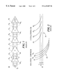
- FIG. 2 is two sets of waveforms showing the overdrive recovery delay of the prior art circuit of FIG. 1;
- FIG. 3 is a schematic view of the multi-stage, low-offset, fast-recovery comparator system of this invention
- FIG. 4 is a set of waveforms showing the improved overdrive recovery delay of the invention of FIG. 3;
- FIG. 5 is a schematic view of a single stage of the multi-stage, low-offset, fast-recovery comparator system of this invention.
- FIG. 6 is a schematic view of a typical embodiment of each of the amplifiers in an amplification stage of this invention.
- FIG. 7 is a flow chart of the method of reducing voltage offset in a single amplification stage of this invention.
- the prior art capacitor coupled multi-stage comparator system 10 can be used to illustrate both the previous method of storing offset canceling voltages on the coupling capacitors and, with the aid of FIG. 2, the source of and additive properties of overdrive recovery delay.
- Prior art capacitor-coupled multi-stage comparator system 10 FIG. 1, produces a considerable amount of lag as the input signal 12 , applied to the first amplifier 14 1 in the amplifier chain 14 1-4 propagates through system 10 to latch 16 . This time delay is induced as a result of the capacitor pairs 18 1-4 used to isolate the individual amplifiers 14 1-4 of the multi-stage comparator system 10 .
- a block of time is set aside prior to the beginning of the comparison sequence to auto-zero the comparator system.
- the comparator 14 1 is disconnected from the input 12 while switches 20 0-4 are closed.
- Each amplifier now has zero volts at its inputs, so its outputs will differ by the output offset voltage. For example, if the first amplifier 14 1 has a gain of 10 and an input offset voltage of 10 mV, outputs 22 and 24 will differ by 100 mV (10 mV*10). Since the pair of capacitors 18 1 are connected together at the input of the second amplifier 14 1 , the 100 mV output offset voltage will also appear as a difference in the voltages on the capacitor pair 18 1 . A similar situation exists with amplifiers 14 2-4 and capacitor pairs 18 2-4 .
- switches 20 0-4 will open, leaving the offset canceling voltages on capacitors 18 1-4 such that if the input 12 to amplifier 14 1 is zero, the input to latch 16 will also be zero, in spite of the voltage differences at the output of each amplifier 14 1-4 .
- FIG. 2 illustrates the overdrive recovery problem of the prior art multi-stage comparator system.
- This figure displays the behavior of the output voltages of each of the four amplifiers of FIG. 1 in relation to time during a non-critical comparison 26 and a critical comparison 28 .
- Reference lines 30 show the limits of the linear (or responsive) region of the input voltage range of each amplifier. This includes an upper limit 32 and a lower limit 34 .
- the linear input range of a comparator is less than the comparator's output voltage range due to its gain. This linear input range represents the only values of input voltage that can cause the comparator's output to change.
- Both of the comparisons shown in FIG. 2 are assumed to be following a previous non-critical comparison that has left the amplifier output voltages well outside the linear input range.
- a voltage is applied to the comparator which is large enough and of the appropriate polarity to drive the comparator's output to its maximum value in the other direction (reverse polarity).
- the output 26 1 of the first amplifier changes first and enters into the linear input range of the second amplifier. When it crosses the center 36 of the linear region 30 , the output 26 2 of the second amplifier starts down towards the linear input range of the third amplifier and so on.
- the overdrive recovery delay is the time from when the input is first applied to the time when the output of the fourth amplifier 26 4 crosses upper limit 32 of active region 30 .
- the voltage applied to the comparator is small enough such that all the outputs will end up in the linear input range.
- the major difference in the critical case is that the rate of change of the outputs in these amplifiers decreases exponentially as they approach their final values. Therefore, the time taken for each output to reach the linear input region 30 of its successor (amplifier) is much greater and, hence, the delay until the output of the fourth amplifier 28 4 reaches upper limit 32 of active region 30 is much greater and is roughly four times the delay of any one amplifier.
- the multi-stage, low-offset, fast-recovery, comparator system 50 FIG. 3, according to this invention, includes a plurality of self-correcting amplification stages 52 1-4 corrected in series.
- Each amplification stage has a reset switch 54 1-4 connected at the output of each amplifier 56 1-4 for returning the output of each amplification stage 52 1-4 to the linear operating input range of the next stage, thereby providing fast response to the next input signal.
- each of these amplification stages will have essentially a zero offset voltage, thus eliminating the problems concerning the amplification inaccuracies described above. Further, while FIG.
- FIG. 3 shows the multi-stage, low-offset, fast-recovery, comparator system 50 as having four amplification stages 52 1-4 , this is for illustrative purposes only and is not intended to be a limitation of the invention.
- the number of stages utilized in the multi-stage, low-offset, fast-recovery, comparator system 50 will be determined by the desired resolution of the system. For example, since this system is often used in an analog to digital converter (ADC), as the number of bits of the ADC is increased, the resolution of the system must be increased accordingly, since the voltage difference between the individual binary values of the output will be decreased.
- ADC analog to digital converter
- FIG. 3 shows a DC-coupled version of the comparator system of this invention.
- capacitors 62 1-4 shown in phantom
- the effectiveness of the reset switch in removing overdrive recovery delay would be compromised.
- the reset switch cannot remove the offset canceling voltages from the coupling capacitors, as the overall zero condition would be altered. If this were the case, when reset switches 54 1-4 were applied, the inputs of comparators 56 2-4 would not be zero (as they are in the present invention) but would be at the negative of the output offset of the previous stage, due to the voltage differences stored on the capacitors. Further, when the reset switches were opened so a comparison can begin, those amplifiers would respond to those offset voltages before responding to the input signal and such offsets would result in an overdrive condition, leading to a recovery delay.
- FIG. 4 shows the behavior of the output of each amplifier 52 1-4 during either a critical or non-critical comparison. Since reset switches 54 1-4 return all the amplifier outputs to the center of the linear input range 60 after every comparison, the nature of the previous comparison is unimportant and there is never an overdrive recovery delay. Reset switches 54 1-4 are opened some time after the input to the comparator is applied. A typical delay between applying the input signal to the amplification stage and opening its respective reset switch is 10 ns. Therefore, the output of the first amplifier 56 1 immediately responds to its input, the output of the second amplifier 56 2 immediately responds to the output of the first amplifier, the output of the third amplifier immediately responds to the output of the second amplifier, and so on, as shown in FIG. 4 . This is all possible because each of these amplifier stages 52 1-4 will have essentially zero offset voltage (as will be explained later in greater detail).
- FIG. 5 a single stage 70 of the multi-stage, low-offset, fast-recovery, comparator system.
- Each stage in the system includes a main amplifier 72 , which is responsive to an input signal 74 received on input terminal 76 and generates an output signal 78 . Further, offset adjustment input terminal 80 is included on main amplifier 72 .
- a typical embodiment of main amplifier 72 is shown in FIG. 6 .
- a local feedback circuit 82 responsive to the output 78 of the main amplifier 72 , provides an offset adjustment signal 84 to the offset adjustment input terminal 80 of main amplifier 72 to compensate for the local offset voltage of main amplifier 72 .
- Capacitor 116 is a storage device which stores the offset adjustment voltage present on offset adjustment input terminals 80 such that the offset of the main amplifier will remain compensated during subsequent operations.
- Local feedback circuit 82 includes a zeroing amplifier circuit 86 , having an input terminal 88 , responsive to the output 78 of the main amplifier 72 , for generating offset adjustment signal 84 .
- a typical embodiment of zeroing amplifier circuit 86 is shown in FIG. 6 .
- Zeroing amplifier circuit 86 FIG. 5, further includes a zeroing amplifier offset reduction circuit 90 for minimizing the input offset voltage of the zeroing amplifier circuit 86 .
- the output offset voltage is the product of the input offset voltage and the gain of the amplifier. For example, if there is a typical input offset voltage of 10-15 millivolts and a gain of 100 on zeroing amplifier circuit 86 , the output offset voltage is 1.00-1.50 volts.
- Zeroing amplifier circuit 86 includes zero adjustment input terminal 94 to compensate for the local offset voltage of zeroing amplifier circuit 86 .
- Zeroing amplifier offset reduction circuit 90 includes: first switching means 96 for applying the offset adjustment signal 84 to zero adjustment input terminal 94 ; and second switching means 98 for applying a predetermined zeroing signal to the signal input terminal 88 of zeroing amplifier circuit 86 . While in this particular situation, second switching means 98 is shown as shorting input terminals 88 together, this is for illustrative purposes only and is not intended to be a limitation of the invention.
- Local feedback circuit 82 includes: first switching means 106 for applying offset adjustment signal 84 to offset adjustment input terminal 80 of main amplifier 72 ; second switching means 108 for applying output signal 78 of main amplifier 72 to input terminal 88 of zeroing amplifier circuit 86 ; third switching means 102 for applying a zero input signal to the input terminal 76 of main amplifier 72 ; and fourth switching means 110 for applying the output of the previous amplification stage 112 to the input terminal 76 of main amplifier 72 . While in this particular situation, third switching means 102 is shown as shorting input terminals 76 together, this is for illustrative purposes only and is not intended to be a limitation of this invention.
- first and second switching means 96 and 98 of zeroing amplifier offset reduction circuit 90 and the first, second, third and fourth switching means 106 , 108 , 102 and 110 of local feedback circuit 82 are described as discrete devices, this is not a limitation of the invention.
- first switching means 96 of zeroing amplifier offset reduction circuit 90 and first switching means 106 of local feedback circuit 82 could be a double pole, double throw (DPDT) switch, which when in the first position, applies offset adjustment signal 84 to zero adjustment input terminal 94 (performing the function of first switching means 96 of zeroing amplifier offset reduction circuit 90 ).
- DPDT double pole, double throw
- Capacitor 112 is a storage device which stores the offset adjustment voltage present on zero adjustment input terminal 94 , such that the offset of the zeroing amplifier will remain compensated during subsequent operations.
- each amplification stage 70 performs a series of three operations, namely: 1) auto-zeroing the zeroing amplifier circuit 86 ; 2) auto-zeroing the main amplifier 72 ; and 3) processing the input signal 74 .
- Each operation will be described in as follows.
- the first step in the operation of amplification stage 70 is auto-zeroing the zeroing amplifier circuit 86 .
- Switching means 98 is closed and switching means 108 is opened to apply a predetermined zeroing signal to the input terminal 88 of zeroing amplifier circuit 86 .
- the predetermined zeroing signal is zero volts and, therefore, the initial input to zero input adjustment terminal 94 is zero volts.
- Switching means 96 is closed and switching means 106 is opened to feed back (via negative feedback) offset adjustment signal 84 to the zero adjustment input terminal 94 of zeroing amplifier circuit 86 .
- Switching means 102 is closed and switching means 110 is opened to apply a predetermined offset signal to input terminal 76 of main amplifier 72 .
- the predetermined offset signal is zero volts and, therefore, the input applied to input terminal 76 of main amplifier 72 is zero volts. Therefore, the output of zeroing amplifier circuit 86 (which is offset adjustment signal 84 ) is equal to the negative of the input offset voltage of the zeroing amplifier. This signal is applied, via negative feedback, to zero input adjustment terminal 94 .
- Storage device 112 typically a capacitor stores the value applied to zero input adjustment terminal 94 . A typical value for this capacitor is 2 pf.
- the next step requires auto-zeroing the main amplifier.
- Switching means 96 is opened and switching means 106 is closed to provide offset adjustment signal 84 to offset adjustment input terminal 80 of main amplifier 72 .
- Storage device 116 (typically a capacitor) stores the value applied to offset adjustment input terminal 80 .
- a typical value for this capacitor is 5 pf
- Switching means 98 is opened and switching means 108 is closed to apply output signal 78 to the input terminal 88 of zeroing amplifier circuit 86 .
- Switching means 102 remains closed and switching means 110 remains open to continue to apply a predetermined offset signal to input terminal 76 of main amplifier 72 . Once these switches are set to these positions, a situation occurs which is similar to that which occurred in the first step.
- the output signal 78 of main amplifier 72 is equal to the output offset voltage of main amplifier 72 .
- This signal is then fed back (via negative feedback) through the zeroing amplifier to the offset adjustment input terminal 80 of main amplifier 72 .
- step 1 by feeding back, via negative feedback, the output offset voltage of the main amplifier 72 to its offset adjustment input terminal 80 , the feedback loop stabilizes to a condition where the input offset voltage is reduced by the product of the gains of the main amplifier 72 and zeroing amplifier 86 . This will be explained below in greater detail.
- each amplification stage of the multi-stage, low-offset, fast-recovery, comparator system appears to be an amplifier with virtually no offset voltage.
- Switching means 110 is closed, applying input signal 74 to input terminal 76 of the first main amplifier 72 . Further, switching means 98 and 108 are opened to isolate the output 78 from the feedback circuit 82 . This allows main amplifier 72 and reset switch 122 to process input signal 74 while minimizing input offset and overdrive recovery delay, thus providing a high resolution output signal 78 .
- open-loop gain of the zeroing amplifier is 1000; the input offset voltage of the zeroing amplifier is 10 mV; the open loop gain of the main amplifier is 10 ; and the input offset voltage of the main amplifier is ⁇ 20 mV.
- the output (offset adjustment signal 84 ) of zeroing amplifier circuit 86 is equal to the gain (1000) times the sum of the signal applied to the input terminal 88 of the zeroing amplifier circuit 86 (Input Zero Amp ), the signal applied to the zero adjustment input terminal 94 of the zeroing amplifier 86 (Adjust Zero Amp ) less the input offset voltage of the zeroing amplifier circuit 86 (10 mV).
- the input terminal 88 of the zeroing amplifier circuit 86 is tied to a zero volt reference voltage.
- Equation (1) the result can be used in Equation (1) for the variable Adjust Zero Amp since the output signal is fed back to the zero adjustment input terminal 94 .
- the resulting transfer function of the offset corrected zeroing amplifier can then be found. Note that the effective input offset voltage of the zeroing amplifier after the offset correction has been reduced from the initial offset (10 mV) to 10 ⁇ V.
- the output ( 78 ) of main amplifier 72 is equal to the gain (10) times the sum of the signal applied to the input terminal 76 of the main amplifier 72 (Input Main Amp ), the signal applied to the offset adjustment input terminal 80 of the main amplifier 72 (Adjust Main Amp ) less the input offset voltage of the main amplifier 72 ( ⁇ 20 mV).
- Output Main Amp 10*(Input Main Amp +Adjust Main Amp +20 mV) (8)
- the input terminal 76 of the main amplifier 72 is connected to a zero volt reference voltage.
- Equation (9) can be inserted into Equation (8).
- the output (offset adjustment signal 84 ) of the zeroing amplifier is now connected, via negative feedback, to the offset adjustment input terminal 80 of the main amplifier.
- the input of the zeroing amplifier is connected to the output of the main amplifier.
- Equations (11) and (12) can now be inserted into the previously derived transfer function of the offset corrected zeroing amplifier (Equation 7).
- Equations (10) and (13) can be combined and solved for the offset adjustment signal that will be developed for the main amplifier during this second step.
- Equation (14) can be inserted into the transfer function of the main amplifier (Equation 8) to derive the transfer function of the combined amplifier stage.
- Output Main Amp 10*(Input Main Amp ⁇ 19.997001 mV+20 mV) (15)
- the effective input offset voltage of the combined amplifier stage after the two steps of offset correction has been reduced from the initial offset of the main amplifier (20 mV) to merely 3 ⁇ V.
- the multiple independently offset corrected amplifier stages are connected in cascade to operate as a high-speed, high-gain comparator.
- Amplifier 125 includes two current sources 126 and 128 which provide current to transistor pairs 130 and 132 .
- the voltage drop across load devices 134 and 136 is the output signal present on the amplifier output terminals.
- the method 150 of reducing voltage offset in a single amplification stage, having a zeroing amplifier and a main amplifier, includes the steps of: reducing 151 the input offset voltage of the zeroing amplifier by a factor essentially equal to the gain of the zeroing amplifier; reducing 153 the input offset voltage of the combined main and zeroing amplifiers by a factor essentially equal to the product of the gains of the main and zeroing amplifiers; and amplifying 154 the input signal to the amplification stage in accordance with the gain of the main amplifier to generate an amplified high-resolution signal.
- the step of reducing 151 the input offset voltage of the zeroing amplifier includes: applying 156 a zero signal to the input terminals of the zeroing amplifier; connecting 158 the zeroing amplifier output signal, via negative feedback, to the zero input adjustment terminal of the zeroing amplifier; and generating and storing 160 an adjustment voltage that reduces the input offset voltage of the zeroing amplifier.
- the step of reducing 153 the input offset voltage of the combined main and zeroing amplifiers includes: applying 162 a zero signal to the input terminals of the main amplifier; connecting 164 the output of the main amplifier to the input of the “offset corrected” zeroing amplifier; connecting 166 the output of the zeroing amplifier, via negative feedback, to the offset adjustment input of the main amplifier; and generating and storing 168 an adjustment voltage that reduces the input offset voltage of the main amplifier.
- Method 150 includes the step of returning 170 the amplified high resolution signal to the operating input range of the next amplification stage to provide fast response to its next input signal.
Landscapes
- Engineering & Computer Science (AREA)
- Power Engineering (AREA)
- Physics & Mathematics (AREA)
- Nonlinear Science (AREA)
- Amplifiers (AREA)
- Manipulation Of Pulses (AREA)
- Analogue/Digital Conversion (AREA)
- Measurement Of Current Or Voltage (AREA)
Priority Applications (5)
| Application Number | Priority Date | Filing Date | Title |
|---|---|---|---|
| US09/412,659 US6429697B1 (en) | 1999-10-05 | 1999-10-05 | Multi-stage, low-offset, fast-recovery, comparator system and method |
| EP00307335A EP1091489B1 (de) | 1999-10-05 | 2000-08-25 | Mehrstufiges Komparatorsystem und -Verfahren mit schneller Erholungszeit und geringem Offset |
| DE60040643T DE60040643D1 (de) | 1999-10-05 | 2000-08-25 | Mehrstufiges Komparatorsystem und -Verfahren mit schneller Erholungszeit und geringem Offset |
| AT00307335T ATE413017T1 (de) | 1999-10-05 | 2000-08-25 | Mehrstufiges komparatorsystem und -verfahren mit schneller erholungszeit und geringem offset |
| JP2000270176A JP3683486B2 (ja) | 1999-10-05 | 2000-09-06 | 多段低オフセット高速回復の比較器システム及び方法 |
Applications Claiming Priority (1)
| Application Number | Priority Date | Filing Date | Title |
|---|---|---|---|
| US09/412,659 US6429697B1 (en) | 1999-10-05 | 1999-10-05 | Multi-stage, low-offset, fast-recovery, comparator system and method |
Publications (1)
| Publication Number | Publication Date |
|---|---|
| US6429697B1 true US6429697B1 (en) | 2002-08-06 |
Family
ID=23633883
Family Applications (1)
| Application Number | Title | Priority Date | Filing Date |
|---|---|---|---|
| US09/412,659 Expired - Lifetime US6429697B1 (en) | 1999-10-05 | 1999-10-05 | Multi-stage, low-offset, fast-recovery, comparator system and method |
Country Status (5)
| Country | Link |
|---|---|
| US (1) | US6429697B1 (de) |
| EP (1) | EP1091489B1 (de) |
| JP (1) | JP3683486B2 (de) |
| AT (1) | ATE413017T1 (de) |
| DE (1) | DE60040643D1 (de) |
Cited By (22)
| Publication number | Priority date | Publication date | Assignee | Title |
|---|---|---|---|---|
| US20030236083A1 (en) * | 2002-04-04 | 2003-12-25 | Magnus Wiklund | Linearity improvement of Gilbert mixers |
| US20040113685A1 (en) * | 2002-12-13 | 2004-06-17 | Abidin Clndra Wldya | DC offset cancellation techniques |
| US20040201417A1 (en) * | 2003-04-09 | 2004-10-14 | Sony Corporation | Differential amplifier, two-stage amplifier including the differential amplifier, and analog-to-digital converter including the differential amplifier |
| US20050277396A1 (en) * | 2004-06-09 | 2005-12-15 | Spyros Pipilos | Apparatus and methods for eliminating DC offset in a wireless communication device |
| US20060223472A1 (en) * | 2005-03-30 | 2006-10-05 | Broadcom Corporation | DC cancellation circuit |
| US20070002505A1 (en) * | 2005-06-22 | 2007-01-04 | Hitachi, Ltd. | Motor control system |
| US20070170982A1 (en) * | 2006-01-24 | 2007-07-26 | Cheng-Jui Chen | Circuit utilizing op-sharing technique and related method thereof |
| US20070257720A1 (en) * | 2005-12-16 | 2007-11-08 | Alexander Krymski D.B.A. Alexima | Analog to digital converter circuit with offset reduction and image sensor using the same |
| US7630464B1 (en) * | 2005-04-19 | 2009-12-08 | Lattice Semiconductor Corporation | Analog-to-digital systems and methods |
| US20100156469A1 (en) * | 2008-12-22 | 2010-06-24 | Electronics And Telecommunications Research Institute | High-speed multi-stage voltage comparator |
| US20100164770A1 (en) * | 2008-12-31 | 2010-07-01 | Hong Kong Applied Science & Technology Research Institute Company Limited | Multi-stage comparator with offset canceling capacitor across secondary differential inputs for high-speed low-gain compare and high-gain auto-zeroing |
| CN101447782B (zh) * | 2007-11-27 | 2011-04-06 | 奇景光电股份有限公司 | 低偏移量比较器及其偏移消除方法 |
| US20110234433A1 (en) * | 2010-03-24 | 2011-09-29 | Fujitsu Semiconductor Limited | A/d converter |
| US8258864B1 (en) | 2011-09-21 | 2012-09-04 | Hong Kong Applied Science And Technology Research Institute Co., Ltd. | Ultra low voltage multi-stage high-speed CMOS comparator with autozeroing |
| WO2012148598A1 (en) * | 2011-04-28 | 2012-11-01 | Analog Devices, Inc. | Noise cancellation system and method for amplifiers |
| US8350597B2 (en) | 2008-10-15 | 2013-01-08 | Nxp B.V. | Low voltage self calibrated CMOS peak detector |
| US8493098B1 (en) * | 2012-03-14 | 2013-07-23 | Honeywell International Inc. | Systems and methods for compensating the input offset voltage of a comparator |
| CN110995213A (zh) * | 2019-11-27 | 2020-04-10 | 芯创智(北京)微电子有限公司 | 一种低失调高精度静态比较器 |
| US11005469B1 (en) * | 2019-11-27 | 2021-05-11 | Robert Bosch Gmbh | Two step high speed auto-zero and self-calibration comparator |
| US11742843B2 (en) * | 2020-04-23 | 2023-08-29 | Silicon Laboratories Inc. | Apparatus for offset cancellation in comparators and associated methods |
| US11764759B2 (en) | 2020-04-23 | 2023-09-19 | Silicon Laboratories Inc. | Apparatus for offset cancellation in comparators and associated methods |
| WO2024021537A1 (zh) * | 2022-07-29 | 2024-02-01 | 普源精电科技股份有限公司 | 失调电压校准电路及校准方法 |
Families Citing this family (5)
| Publication number | Priority date | Publication date | Assignee | Title |
|---|---|---|---|---|
| WO2002084862A1 (en) * | 2001-04-11 | 2002-10-24 | Koninklijke Philips Electronics N.V. | High duty cycle offset compensation for operational amplifiers |
| US6583660B2 (en) * | 2001-05-25 | 2003-06-24 | Infineon Technologies Ag | Active auto zero circuit for time continuous open loop amplifiers |
| US6753727B2 (en) | 2002-06-13 | 2004-06-22 | Skyworks Solutions, Inc. | Sequential DC offset correction for amplifier chain |
| JP2009081749A (ja) * | 2007-09-27 | 2009-04-16 | Hitachi Ltd | 低オフセット入力回路 |
| US9602062B2 (en) | 2014-06-30 | 2017-03-21 | Qualcomm Incorporated | Audio switching amplifier |
Citations (3)
| Publication number | Priority date | Publication date | Assignee | Title |
|---|---|---|---|---|
| US4599602A (en) * | 1983-08-03 | 1986-07-08 | Matsushita Electric Industrial Co., Ltd. | Serial-type A/D converter utilizing folding circuit cells |
| US4883987A (en) | 1988-05-04 | 1989-11-28 | Texas Instruments Incorporated | Comparator circuit having a fast recovery time |
| US5600275A (en) | 1994-04-29 | 1997-02-04 | Analog Devices, Inc. | Low-voltage CMOS comparator with offset cancellation |
Family Cites Families (3)
| Publication number | Priority date | Publication date | Assignee | Title |
|---|---|---|---|---|
| CH659745A5 (de) * | 1983-06-08 | 1987-02-13 | Landis & Gyr Ag | Verstaerker mit niedriger offset-spannung. |
| IT1225620B (it) * | 1988-10-06 | 1990-11-22 | Sgs Thomson Microelectronics | Comparatore cmos interamente differenziale a grande risoluzione |
| US4962323A (en) * | 1989-07-12 | 1990-10-09 | National Semiconductor Corporation | High speed auto zero comparator |
-
1999
- 1999-10-05 US US09/412,659 patent/US6429697B1/en not_active Expired - Lifetime
-
2000
- 2000-08-25 AT AT00307335T patent/ATE413017T1/de not_active IP Right Cessation
- 2000-08-25 EP EP00307335A patent/EP1091489B1/de not_active Expired - Lifetime
- 2000-08-25 DE DE60040643T patent/DE60040643D1/de not_active Expired - Lifetime
- 2000-09-06 JP JP2000270176A patent/JP3683486B2/ja not_active Expired - Lifetime
Patent Citations (3)
| Publication number | Priority date | Publication date | Assignee | Title |
|---|---|---|---|---|
| US4599602A (en) * | 1983-08-03 | 1986-07-08 | Matsushita Electric Industrial Co., Ltd. | Serial-type A/D converter utilizing folding circuit cells |
| US4883987A (en) | 1988-05-04 | 1989-11-28 | Texas Instruments Incorporated | Comparator circuit having a fast recovery time |
| US5600275A (en) | 1994-04-29 | 1997-02-04 | Analog Devices, Inc. | Low-voltage CMOS comparator with offset cancellation |
Non-Patent Citations (1)
| Title |
|---|
| Behzad Razavi and Bruce A. Wooley, Design Techniques for High-Speed, High Resolution Comparators, IEEE Journal of Solid State Circuits, vol. 27, No. 12, Dec. 1992. |
Cited By (38)
| Publication number | Priority date | Publication date | Assignee | Title |
|---|---|---|---|---|
| US7054609B2 (en) * | 2002-04-04 | 2006-05-30 | Telefonaktiebolaget Lm Ericsson (Publ) | Linearity improvement of Gilbert mixers |
| US20030236083A1 (en) * | 2002-04-04 | 2003-12-25 | Magnus Wiklund | Linearity improvement of Gilbert mixers |
| US20040113685A1 (en) * | 2002-12-13 | 2004-06-17 | Abidin Clndra Wldya | DC offset cancellation techniques |
| US6819172B2 (en) * | 2002-12-13 | 2004-11-16 | Intel Corporation | DC offset cancellation techniques |
| GB2401735A (en) * | 2003-04-09 | 2004-11-17 | Sony Corp | A comparator with isolatable inputs for reduced noise in a sub-ranging ADC |
| US6985030B2 (en) | 2003-04-09 | 2006-01-10 | Sony Corporation | Differential amplifier, two-stage amplifier including the differential amplifier, and analog-to-digital converter including the differential amplifier |
| GB2401735B (en) * | 2003-04-09 | 2005-07-06 | Sony Corp | Differential amplifier, two-stage amplifier including the differential amplifier, and analog-to-digital converter including the differential amplifier |
| US20040201417A1 (en) * | 2003-04-09 | 2004-10-14 | Sony Corporation | Differential amplifier, two-stage amplifier including the differential amplifier, and analog-to-digital converter including the differential amplifier |
| US20050277396A1 (en) * | 2004-06-09 | 2005-12-15 | Spyros Pipilos | Apparatus and methods for eliminating DC offset in a wireless communication device |
| US7155185B2 (en) * | 2004-06-09 | 2006-12-26 | Theta Microelectronics, Inc. | Apparatus and methods for eliminating DC offset in a wireless communication device |
| US7917114B2 (en) * | 2005-03-30 | 2011-03-29 | Broadcom Corp. | DC cancellation circuit |
| US20060223472A1 (en) * | 2005-03-30 | 2006-10-05 | Broadcom Corporation | DC cancellation circuit |
| US7630464B1 (en) * | 2005-04-19 | 2009-12-08 | Lattice Semiconductor Corporation | Analog-to-digital systems and methods |
| US20070002505A1 (en) * | 2005-06-22 | 2007-01-04 | Hitachi, Ltd. | Motor control system |
| US7423403B2 (en) * | 2005-06-22 | 2008-09-09 | Hitachi, Ltd. | Motor control system |
| US7400279B2 (en) * | 2005-12-16 | 2008-07-15 | Alexander Krymski | Circuits and methods with comparators allowing for offset reduction and decision operations |
| US20070257720A1 (en) * | 2005-12-16 | 2007-11-08 | Alexander Krymski D.B.A. Alexima | Analog to digital converter circuit with offset reduction and image sensor using the same |
| US20070170982A1 (en) * | 2006-01-24 | 2007-07-26 | Cheng-Jui Chen | Circuit utilizing op-sharing technique and related method thereof |
| CN101447782B (zh) * | 2007-11-27 | 2011-04-06 | 奇景光电股份有限公司 | 低偏移量比较器及其偏移消除方法 |
| US8350597B2 (en) | 2008-10-15 | 2013-01-08 | Nxp B.V. | Low voltage self calibrated CMOS peak detector |
| US7977979B2 (en) | 2008-12-22 | 2011-07-12 | Electronics And Telecommunications Research Institute | High-speed multi-stage voltage comparator |
| US20100156469A1 (en) * | 2008-12-22 | 2010-06-24 | Electronics And Telecommunications Research Institute | High-speed multi-stage voltage comparator |
| US20100164770A1 (en) * | 2008-12-31 | 2010-07-01 | Hong Kong Applied Science & Technology Research Institute Company Limited | Multi-stage comparator with offset canceling capacitor across secondary differential inputs for high-speed low-gain compare and high-gain auto-zeroing |
| US7764215B2 (en) | 2008-12-31 | 2010-07-27 | Hong Kong Applied Science And Technology Research Institute Co., Ltd. | Multi-stage comparator with offset canceling capacitor across secondary differential inputs for high-speed low-gain compare and high-gain auto-zeroing |
| CN101764612B (zh) * | 2008-12-31 | 2012-09-26 | 香港应用科技研究院有限公司 | 多阶段比较器 |
| US20110234433A1 (en) * | 2010-03-24 | 2011-09-29 | Fujitsu Semiconductor Limited | A/d converter |
| US8368577B2 (en) | 2010-03-24 | 2013-02-05 | Fujitsu Semiconductor Limited | A/D converter |
| US8508257B2 (en) | 2011-04-28 | 2013-08-13 | Analog Devices, Inc. | Noise cancellation system and method for amplifiers |
| WO2012148598A1 (en) * | 2011-04-28 | 2012-11-01 | Analog Devices, Inc. | Noise cancellation system and method for amplifiers |
| US8258864B1 (en) | 2011-09-21 | 2012-09-04 | Hong Kong Applied Science And Technology Research Institute Co., Ltd. | Ultra low voltage multi-stage high-speed CMOS comparator with autozeroing |
| US8493098B1 (en) * | 2012-03-14 | 2013-07-23 | Honeywell International Inc. | Systems and methods for compensating the input offset voltage of a comparator |
| US8736312B2 (en) | 2012-03-14 | 2014-05-27 | Honeywell International Inc. | Systems and methods for compensating the input offset voltage of a comparator |
| CN110995213A (zh) * | 2019-11-27 | 2020-04-10 | 芯创智(北京)微电子有限公司 | 一种低失调高精度静态比较器 |
| US11005469B1 (en) * | 2019-11-27 | 2021-05-11 | Robert Bosch Gmbh | Two step high speed auto-zero and self-calibration comparator |
| CN110995213B (zh) * | 2019-11-27 | 2023-07-07 | 芯创智创新设计服务中心(宁波)有限公司 | 一种低失调高精度静态比较器 |
| US11742843B2 (en) * | 2020-04-23 | 2023-08-29 | Silicon Laboratories Inc. | Apparatus for offset cancellation in comparators and associated methods |
| US11764759B2 (en) | 2020-04-23 | 2023-09-19 | Silicon Laboratories Inc. | Apparatus for offset cancellation in comparators and associated methods |
| WO2024021537A1 (zh) * | 2022-07-29 | 2024-02-01 | 普源精电科技股份有限公司 | 失调电压校准电路及校准方法 |
Also Published As
| Publication number | Publication date |
|---|---|
| JP2001144556A (ja) | 2001-05-25 |
| EP1091489B1 (de) | 2008-10-29 |
| DE60040643D1 (de) | 2008-12-11 |
| EP1091489A3 (de) | 2004-06-09 |
| JP3683486B2 (ja) | 2005-08-17 |
| EP1091489A2 (de) | 2001-04-11 |
| ATE413017T1 (de) | 2008-11-15 |
Similar Documents
| Publication | Publication Date | Title |
|---|---|---|
| US6429697B1 (en) | Multi-stage, low-offset, fast-recovery, comparator system and method | |
| US6480132B1 (en) | A/D converter with higher speed and accuracy and lower power consumption | |
| EP0363332B1 (de) | Voll differentieller CMOS-Komparator mit hoher Auflösung | |
| US5113090A (en) | Voltage comparator | |
| US6441769B1 (en) | Overcoming finite amplifier gain in a pipelined analog to digital converter | |
| EP0849883B1 (de) | Analog-Digital-Wandler | |
| CN105959008A (zh) | 预放大器以及包括其的比较器和模数转换装置 | |
| US7924206B2 (en) | Switched capacitor circuit and pipeline A/D converter | |
| US6498530B1 (en) | Auto-zeroed ping-pong amplifier with low transient switching | |
| JPH09326698A (ja) | オフセットを補正する方法および装置 | |
| EP0886377B1 (de) | Chopper-Komparator für Spannungen | |
| US7701256B2 (en) | Signal conditioning circuit, a comparator including such a conditioning circuit and a successive approximation converter including such a circuit | |
| US9685913B2 (en) | Auto-zero differential amplifier | |
| JPH06294825A (ja) | 差動cmosピーク検出回路 | |
| US7173556B2 (en) | Amplifier circuit and analog-to-digital circuit using the same | |
| US7405625B1 (en) | Common-mode control structures and signal converter systems for use therewith | |
| US6404374B1 (en) | Comparator circuit for analog-to-digital converter | |
| US7034729B2 (en) | Adding circuit suitable for sigma-delta modulator circuits | |
| US7567197B2 (en) | Cascade comparator and control method thereof | |
| US6097248A (en) | Switched capacitor amplifier with one-clock delay | |
| US7696916B2 (en) | Parallel type analog-to-digital conversion circuit, sampling circuit and comparison amplification circuit | |
| EP1105971B1 (de) | Analog-zu-digitalkonvertierer mit fliessendem punkt | |
| US20020030544A1 (en) | System and method providing level shifting in single ended to differential conversion | |
| US8471753B1 (en) | Pipelined analog-to-digital converter and method for converting analog signal to digital signal | |
| US6614378B2 (en) | Sampling processing device and imaging apparatus using it |
Legal Events
| Date | Code | Title | Description |
|---|---|---|---|
| AS | Assignment |
Owner name: ANALOG DEVICES, INC., MASSACHUSETTS Free format text: ASSIGNMENT OF ASSIGNORS INTEREST;ASSIGNORS:AMAZEEN, BRUCE EDWARD;COLN, MICHAEL C.W.;WAYNE, SCOTT;AND OTHERS;REEL/FRAME:010302/0768;SIGNING DATES FROM 19990928 TO 19990929 |
|
| STCF | Information on status: patent grant |
Free format text: PATENTED CASE |
|
| FPAY | Fee payment |
Year of fee payment: 4 |
|
| FPAY | Fee payment |
Year of fee payment: 8 |
|
| FPAY | Fee payment |
Year of fee payment: 12 |