US6421576B1 - Method and device to control an engraving device - Google Patents
Method and device to control an engraving device Download PDFInfo
- Publication number
- US6421576B1 US6421576B1 US09/254,293 US25429399A US6421576B1 US 6421576 B1 US6421576 B1 US 6421576B1 US 25429399 A US25429399 A US 25429399A US 6421576 B1 US6421576 B1 US 6421576B1
- Authority
- US
- United States
- Prior art keywords
- engraving
- values
- tool
- depth
- control signal
- Prior art date
- Legal status (The legal status is an assumption and is not a legal conclusion. Google has not performed a legal analysis and makes no representation as to the accuracy of the status listed.)
- Expired - Fee Related
Links
Images


Classifications
-
- B—PERFORMING OPERATIONS; TRANSPORTING
- B41—PRINTING; LINING MACHINES; TYPEWRITERS; STAMPS
- B41C—PROCESSES FOR THE MANUFACTURE OR REPRODUCTION OF PRINTING SURFACES
- B41C1/00—Forme preparation
- B41C1/02—Engraving; Heads therefor
- B41C1/04—Engraving; Heads therefor using heads controlled by an electric information signal
- B41C1/045—Mechanical engraving heads
Definitions
- the invention relates to the area of electronic reproduction technology, and relates to a method and a means for controlling the engraving device of an electronic engraving machine for engraving print forms, in particular of print cylinders, for rotogravure by means of an engraving tool as a cutting tool, and relates to a corresponding engraving device.
- an engraving device with an engraving tool as a cutting tool moves in the axial direction on a rotating print cylinder, and the engraving tool, controlled by an engraving signal, cuts a series of recesses arranged in a rotogravure raster, which recesses are called cups in the following, into the jacket surface of the print cylinder.
- the engraving signal is formed from the superposition of an image signal, representing the tone values between “black” and “white,” with a periodic raster signal, which, together with the relative speed between the print cylinder and the engraving device, determines the geometry of the rotogravure raster.
- the image signal controls the penetration depths of the engraving tool into the jacket surface of the print cylinder, and thereby the volumes of the engraved cups, in a manner corresponding to the tone values to be reproduced.
- the cups engraved into the print cylinder are filled with more or less ink corresponding to their volumes, which ink is then transferred onto the print medium during the print process from the cups of the print cylinder.
- an electromagnetic engraving device i.e., an engraving device with an electromagnetic drive element for the engraving tool.
- the electromagnetic drive element consists of a stationary electromagnet that is charged with the engraving signal, in the air gap of which the armature of a rotating system moves.
- the rotating system consists of a shaft, the armature, a bearing for the shaft, and a damping means. One end of the shaft goes over into a resilient torsion rod that is clamped in a spatially fixed manner, while the other end of the shaft bears a lever to which the engraving tool is attached.
- an electrical torque is exerted on the armature of the shaft, which is counteracted by the mechanical torque of the torsion rod.
- the electrical torque deflects the shaft from an idle position by an angle of rotation proportional to the engraving signal, and the torsion rod brings the shaft back into the idle position.
- the engraving tool executes a stroke directed in the direction toward the jacket surface of a print cylinder, which stroke determines the penetration depth of the engraving tool into the print cylinder.
- the engraving tool in particular given abrupt changes of the engraving signal at steep density transitions (contours), has a transient response that is subject to error, which is influenced by the rotational inertia and the degree of damping of the rotational system.
- An error-prone transient response of the engraving tool results in engraving errors on the print cylinder or, respectively, disturbing changes in tone value in the printing.
- Given an insufficient damping of the rotational system disturbing multiple contours arise at density jumps, due to overshootings of the engraving tool.
- the engraving tool Given an excessively strong damping of the rotational system, the engraving tool can follow too slowly at steep density transitions, and the target engraving depth is reached only at a distance after the jump in density, whereby steep jumps in density are reproduced imprecisely.
- EP-B-0 437 421 a method is known with which the transient response of an electromagnetic engraving device is improved by means of a specific electrical driving of the engraving device.
- the image signal is briefly intermediately stored in a memory stage, and is supplied to the engraving device in a manner delayed by the storage time.
- a correction signal is derived from the image signal that can be adjusted in its amplitude and in its effective duration, which correction signal is supplied to the engraving device in a chronologically rapid manner.
- a magnetostrictive engraving device for the engraving of print cylinders, i.e., an engraving device with a magnetostrictive drive element for the engraving tool.
- the magnetostrictive drive element essentially comprises a cylindrical actuator made of a magnetostrictive material, to which the engraving tool is coupled.
- the actuator is surrounded by an annular auxiliary coil through which a direct current flows and by an annular driver coil through which an alternating current flows.
- the direct current produces a constant magnetic field in the auxiliary coil for the pre-magnetization of the actuator.
- the actuator is expanded into a pre-stressed position.
- the alternating current produces a dynamic magnetic field with changing direction in the driver coil, which is superimposed on the constant magnetic field, whereby the resulting magnetic field causes, according to the direction, a further expansion of the actuator into an operating position for engraving or a contraction of the actuator into an idle position.
- the drive circuit for the magnetostrictive engraving device consists essentially of a current generator for the production of the direct current for the auxiliary coil and a voltage/current transducer.
- the image signal, containing the engraving information, and an alternating voltage with constant frequency are supplied as a raster signal to the voltage/current transducer, which raster signal effects the oscillating piston motion of the engraving tool for the production of the rotogravure raster.
- the object of the present invention is thus to improve a method and a means for controlling the engraving device for engraving print forms, in particular of print cylinders, for rotogravure by means of an engraving tool as a cutting tool, as well as improving an engraving device, in such a way that disturbing changes of operating parameters of the engraving device are compensated in order to achieve rapid and error-free engravings.
- a method for driving an engraving device of an electronic engraving machine for engraving a print form. Items of engraving information representing tone values are stored as engraving data. The information for engraving of a sequence of cups in a main engraving direction into the print form with an engraving tool as a cutting tool are retrieved. The engraving data that have been read out are converted according to a first function into at least one engraving depth target value per cup.
- a control signal for an engraving tool drive system is activated at a beginning of the engraving of a cup so that the engraving tool executes an operating stroke from an idle position in a direction towards the print form, and after the engraving of the cup the tool is guided back into the idle position for the reset element. In the engraving of the cups, operational strokes of the engraving tool are continuously measured from the idle position.
- a distance between a jacket surface of the print form and the engraving tool is continuously measured in a region of the engraving tool.
- Engraving depth actual values are determined from differences between the operational strokes and the respective distance.
- the engraving depth target values are compared with the determined engraving depth actual values.
- the control signal is modified given equality of the engraving depth target values and the engraving depth actual values.
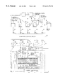
- FIG. 1 shows the design of an embodiment for an engraving device for engraving print forms for rotogravure, as well as an embodiment for a means for controlling the engraving device, in the form of a schematic block switching diagram;
- FIG. 2 a shows an idle position of an engraving tool of an engraving device
- FIG. 2 b shows the engraving tool of the engraving device having done an operational stroke, whereby a first distance actual value is measured
- FIG. 2 c shows the engraving tool of the engraving device having done the same operational stroke, whereby a second distance actual value is measured
- FIG. 2 d shows the engraving tool of the engraving device having done the same operational stroke, whereby a third distance actual value is measured
- FIG. 3 a shows a first partial block of a schematic block switching diagram of an engraving control circuit
- FIG. 3 b shows a second partial block of a schematic block switching diagram of the engraving control circuit
- FIG. 4 a shows the temporal signal pattern of a pulse of a read pulse sequence
- FIG. 4 b shows the temporal signal pattern of an actuator control current
- FIG. 4 c shows the temporal signal pattern of a control signal
- FIG. 4 d shows cross-sections through two engraved cups.
- FIG. 1 shows the design of an embodiment for an engraving device for the engraving of print forms, in particular of print cylinders, for rotogravure, in a sectional representation, as well as an embodiment for a [means] unit for controlling the engraving device, in the form of a schematic block switching diagram.
- the engraving device 1 with an engraving tool 2 as a cutting tool engraves a series of cups in the circumferential direction (main engraving direction) in the jacket surface of a rotating print cylinder 3 , only a section of which is indicated.
- the surface engraving takes place by means of a relative motion between the engraving device 1 and the print cylinder 3 in the axial direction (secondary engraving direction) of the print cylinder 3 .
- the engraving device 1 essentially is formed of a drive system for the engraving tool 2 .
- the engraving tool drive system can be an electromagnetic drive system or else a drive system with a solid-state actuator element, e.g. made of an electrostrictive, piezocrystalline, or magnetostrictive material.
- the engraving tool drive system comprises a cylindrical actuator element 4 made of a magnetostrictive material and a magnet coil 5 that surrounds the actuator element 4 .
- the actuator element 4 is designed as a massive body, or is formed of a number of magnetostrictive individual elements with insulating intermediate layers.
- a magnetostrictive material for example the material Terfenol-DTM, commercially available from the company Etrema Products, Inc., Ames, Iowa, can be used.
- An actuator control current I S that flows through the magnet coil 5 produces in the magnet coil 5 a magnetic field in the direction of the cylinder axis of the actuator element 4 .
- the actuator element 4 By means of the magnetic field, the actuator element 4 essentially experiences a change of length in the direction of its cylinder axis.
- One frontal side of the actuator element 4 is connected with a stationary abutment 7 via a pressure force sensor 6 .
- a front plate 8 is attached, on which the engraving tool 2 is mounted with an engraving tool tip, e.g. made of a diamond.
- the pressure force sensor 6 can alternatively be located between the front plate 8 and the actuator element 4 , or it is also possible for two pressure force sensors to be mounted between the actuator element 4 actuator element 4 and the front plate 8 .
- the engraving device 1 is oriented to the print cylinder 3 in such a way that the tip of the engraving tool 2 is directed radially onto the print cylinder 3 .
- the change in length of the actuator element 4 causes an operating stroke H of the engraving tool 2 in the direction towards the print cylinder 3 .
- the magnitude of the operating stroke H is dependent on the actuator control current I S is supplied to the magnet coil 5 .
- the relationship between the operational stroke H and the actuator control current I S is approximately linear if the operating point in the linear part of the characteristic curve of the actuator element 4 is located outside saturation.
- a mechanical lever system or a hydraulic system can additionally be connected between the engraving tool 2 and the actuator element 4 .
- a suitable power assist may also be intermediately connected.
- the actuator element 4 is pre-stressed by a reset element 9 whose reset force brings the actuator element 4 with the engraving tool 2 into a defined idle position after an operating stroke H.
- the resetting force is produced by a mechanical reset element 9 that is formed of at least one tension spring, e.g. of two pre-stressed tension springs 10 , 11 connected in series, free ends of which are fastened to the abutment 7 and to the front plate 8 .
- the mechanical reset element 9 comprises a tractive force sensor 12 , which, as shown in the embodiment, is attached between the tension springs 10 , 11 .
- the tractive force sensor 12 can also be attached between the front plate 8 and the tension spring 10 , or between the tension spring 11 and the abutment 7 . It is also possible to provide several tractive force sensors. Piezocrystalline pressure pickups can for example be used as a pressure force sensor 6 and tractive force sensor 12 .
- a mechanical reset element with tractive springs instead of a mechanical reset element with tractive springs, another reset element, e.g. made of a magnetostrictive material, with a tractive force measurement apparatus, can also be used.
- the specified construction of the engraving device 1 can be modified in any suitable manner.
- the operational strokes H of the engraving tool 2 from its idle position in the direction towards the jacket surface of the print cylinder 3 are measured by means of a stationary first distance sensor 13 , which determines for example the respective distance to the movable front plate 8 .
- the measurement signal produced in the first distance sensor 13 is supplied to a first measurement amplifier 14 , in which the measurement signal is amplified and linearized corresponding to the non-linear characteristic curve of the first distance sensor 13 .
- the measurement amplifier 14 is thereby calibrated in such a way that in the idle position of the engraving tool the measurement signal has the value zero.
- the measurement signal at the output of the first measurement amplifier 14 is thus a measure for the operational stroke actual value HIST of the engraving tool 2 from its idle position (FIG. 2 ).
- the distance A between the jacket surface of the print cylinder 3 and the engraving tool 2 in its idle position can, for example, fluctuate due to a non-roundness, a deformation, or a faulty mounting of the print cylinder 3 . Since the jacket surface of the print cylinder 3 serves as a reference surface for the engraving depth of the engraving tool 2 , the distances A are respectively measured at the location of engraving of the cups, by means of a second distance sensor 15 .
- the second distance sensor 15 can be fastened to the movable front plate 8 or can be stationary.
- the measurement signal produced in the second distance sensor 15 is supplied to a second measurement amplifier 16 , and is there likewise amplified, and is linearized corresponding to the non-linear characteristic curve of the distance sensor 15 .
- the measurement amplifier 16 is thereby adjusted in such a way that the measurement signal at the output of the second measurement amplifier 16 is a measure for the respective distance actual values A IST between the jacket surface of the print cylinder 3 and the engraving tool 2 in its idle position (FIG. 2 ).
- Capacitive or optical sensors can for example be used as distance sensors 13 , 15 .
- the difference values between the operational stroke actual values H IST of the engraving tool 2 and the distance actual values A IST between the jacket surface of the print cylinder 3 and the engraving tool 2 in its idle position at the engraving location of the cups yield, in the engraving, the engraving depth actual values E IST of the cups (FIG. 2 ).
- the engraving depths of the cups are a measure for the tone values to be reproduced.
- the pressure forces are measured with which the engraving tool 2 penetrates into the print cylinder 3 , or, respectively, with which the basic surface of the actuator element 4 presses on the abutment 7 . Up until contact between the engraving tool 2 and the jacket surface of the print cylinder 3 , the pressure force is zero, and then increases, due to the increasing cross-sectional surface of the engraving tool 2 , with the penetration depth of the engraving tool 2 into the print cylinder 3 .
- the measured pressure forces are in addition a measure for the material hardness, possibly differing in a location-dependent manner, of the print cylinder 3 to be engraved, and for the cutting quality or, respectively, for the degree of wear of the engraving tool 2 .
- the measurement signal produced in the pressure force sensor 6 is supplied to a third measurement amplifier 15 , in which the measurement signal is likewise amplified and linearized corresponding to the non-linear characteristic curve of the pressure force sensor 6 .
- the linearized measurement signal at the output of the third measurement amplifier 7 are the pressure force actual values D IST , with which the engraving tool 2 penetrates into the print cylinder 3 .
- a fourth measurement amplifier 18 the measurement signal of the tractive force sensor 12 at the reset element 9 is converted into a linearized measurement signal, which is a measure for the tractive force actual values Z IST with which the actuator element 4 is reset into its idle position and pre-stressed. Due to the change in length of the tractive springs 10 , 11 , the tractive force is dependent on the operating strokes H or, respectively, on the distances A. With the aid of the tractive force measurement, fluctuations of the reset force, due for example to a defective tractive spring or due to the spring constants changing with temperature of the tractive springs, can be determined. Impermissible fluctuations of the tractive force can be displayed. With the aid of the results of the tractive force measurement, a correction of the pressure force measurement can also advantageously be carried out.
- the measured operational stroke actual values H IST , the distance actual values A IST , the pressure force actual values D IST and the tractive force actual values Z IST move via lines 19 , 20 , 21 , 22 to actual value inputs of an engraving control circuit 23 .
- the engraving control circuit 23 additionally comprises target value inputs that are charged with corresponding target values.
- the engraving data “GD” required for the engraving of the print cylinder 3 are stored in an engraving data memory 24 .
- An engraving datum of at least 30 one byte is allocated to each cup to be engraved, which datum contains, as engraving information, the tone value to be reproduced between “0” (white) and “255” (black).
- the engraving data GD are obtained for example in a scanner by means of point-by-point and line-by-line optoelectronic scanning of an image to be reproduced.
- the engraving data GD are read out from the engraving data memory 24 by means of the pulses of a read pulse sequence T L .
- the read pulse sequence T L is obtained in a clock generator 25 .
- the clock generator 25 is for example designed as a rotary impulse generator that is coupled mechanically with the shaft of the print cylinder 3 , so that the read pulse sequence T L is synchronized with the rotational motion of the print cylinder 3 .
- the engraving times for the cups are derived from the pulses of the read pulse sequence T L .
- the pulse spacings determine the cup spacings in the circumferential direction, corresponding to the rotogravure raster.
- the axial cup spacings of the rotogravure raster are determined by means of the relative motion between the engraving device 1 and the print cylinder 3 ) in the axial direction of the print cylinder 3 .
- the engraving data GD read out from the engraving data memory 24 are supplied in parallel to four function generators 27 , 28 , 29 , 30 via a line 26 .
- the function generators 27 , 28 , 29 , 30 are designed as table memories with integrated D/A converters, in which the engraving data GD are converted into analog values on the basis of functions stored in tabular form, namely into the engraving depth target values E SOLL for the cups, into the pressure force target values D SOLL and into the tractive force target values Z SOLL , as well as into engraving signal values G for driving the actuator element 4 .
- a distance target value A SOLL for the distance between the print cylinder 3 and the engraving tool idle position is predetermined in a target value generator 31 .
- various material hardnesses of the print cylinder 3 to be engraved can be manually inputted.
- an engraving depth target value E SOLL is stored for each engraving datum GD, which target value indicates the maximum target engraving depth of the relevant cup.
- a multiplicity of engraving depth target values E SOLL can also be stored for each engraving datum GD in the form of an engraving depth profile for the relevant cup, which describes the desired path of the engraving tool 2 upon insertion and withdrawal into the or out of the print cylinder 3 during the engraving of a cup.
- the engraving depth target values E SOLL of the engraving depth profile are read out with a pulse sequence from the table memory 27 , which has a correspondingly higher frequency than the read pulse sequence T L .
- the engraving signal values G are stored retrievably by means of the functionally associated engraving data “GD”.
- the greater the penetration depth of the engraving tool 2 the larger the engraving signal values G or, respectively, the larger the forces that are required for the penetration of the engraving tool 2 into the print cylinder 3 , due to the increasing cross-sectional surface of the engraving tool 2 .
- the pressure force target value D SOLL thereby corresponds to the maximum pressure force that occurs approximately when this engraving depth is reached.
- the tractive force target value Z SOLL for a particular engraving depth thereby corresponds to the maximum tractive force that occurs approximately when this engraving depth is reached.
- the engraving signal values G, the pressure force target values D SOLL , and the tractive force target values Z SOLL are dependent not only on the engraving data GD, but also on the material hardness of the print cylinder 3 .
- several value tables with the parameter “material hardness” are usefully stored in the three table memories 28 , 29 , 30 , of which a respective value table is selected, via a control line 33 , corresponding to the “material hardness” input in the input stage 32 , and this value table is activated for the engraving.
- predetermined engraving data GD in the form of a tone value wedge between “black” and “white,” a number of cups are engraved into the print cylinders 3 of different material hardnesses.
- the determined values are supplied from the table memories 27 , 28 , 29 , 30 to the target value inputs of the engraving control circuit 23 via lines 34 , 35 , 36 , 37 .
- the distance target value A SOLL predetermined in the target value generator 31 , for the distance A between the jacket surface of the print cylinder 3 and the engraving tool 2 in its idle position is supplied to the target value inputs of the engraving control circuit 23 .
- an actuator control voltage Us is produced from the engraving signal values G, which control voltage is supplied to a voltage/current transducer 40 via a line 39 .
- the actuator control voltage U S is converted into the actuator control current I s for the actuator element 4 , which current is supplied to this element via a line 41 .
- FIG. 2 shows various operational strokes H of the engraving tool 2 during the engraving, in the form of graphic representations.
- FIG. 2 a shows the engraving tool 2 in the idle position 45 .
- the operational stroke actual value H IST and the measurement signal at the output of the measurement amplifier 14 (FIG. 1) are likewise equal to zero.
- the second distance sensor 15 measures the momentary distance actual value A IST between the print cylinder 3 and the engraving tool 2 in its idle position 45 .
- the engraving tool 2 is in an operational position 46 , in which the engraving tool 2 has executed an operational stroke H IST for the engraving of a cup in the print cylinder 3 and has penetrated into the print cylinder 3 .
- the operational stroke actual value H IST that has been achieved is measured by the first distance sensor 13 (FIG. 1 ).
- the second distance sensor 15 (FIG. 1) has in turn determined the momentary distance actual value A IST , whereby it is assumed that the distance A is constant.
- the engraving depth actual value E IST of the engraving tool 2 in the print cylinder 3 which determines the tone value to be reproduced, results from the difference between the measured operational stroke actual value H IST and the measured distance actual value A IST .
- the engraving tool 2 has executed the same actual operating stroke H IST in the operational position 45 as in FIG. 2 b , but the distance actual value A IST may have increased due to a non-roundness of the print cylinder 3 or a faulty bearing of the print cylinder 3 .
- the operational stroke must be correspondingly enlarged in order to achieve the same engraving depth as in FIG. 2 b.
- the engraving tool 2 has again executed the same actual operational stroke H IST in the operating position 45 as in FIG. 2 b , but the distance actual value A IST may have become smaller due to a non-roundness of the print cylinder 3 .
- the operational stroke H must be correspondingly reduced in order again to achieve the same engraving depth as in FIG. 2 b.
- FIG. 3 shows a schematic block switching diagram of the engraving control circuit 23 , divided into two partial block switching diagrams according to FIGS. 3 a and 3 b.
- a first difference stage 47 in a first difference stage 47 the difference values between the distance target value A SOLL , predetermined in the target value generator 31 , and the distance actual values A IST , supplied by the second measurement amplifier 16 , are continuously formed.
- the difference values are a measure for the distance fluctuations between the jacket surface of the print cylinder 3 and the idle position of the engraving tool.
- the difference values on a line 48 serve as correction values K for value correction on the basis of the determined distance fluctuations.
- the engraving depth actual values E IST of the engraved cups are continuously determined by means of difference formation between the operational stroke actual values H IST , coming from the first measurement amplifier 14 , and the distance actual values A IST coming from the second measurement amplifier 16 .
- the engraving depth target values E SOLL read out from the table memory 27 are then compared with the engraving depth actual values E IST in a first comparator 50 .
- a first correction stage 51 the engraving signal values G read out from the table memory 28 are corrected corresponding to the determined distance fluctuations by means of sign-correct addition of the correction values K on the line 48 .
- the corrected engraving signal values G are supplied to the signal input of a controllable actuator amplifier 52 , which produces at its signal output the actuator control voltage U S .
- the actuator control voltage U S is supplied to the voltage/current transducer 40 via the line 39 , which transducer converts this control voltage into the actuator control current I s for the actuator element 4 of the engraving device 4 .
- the engraving depth target values E SOLL read out from the table memory 27 are additionally supplied to a pulse delay stage 53 to which the read pulse sequence T L produced in the pulse generator 1 is supplied via a line 54 .
- the individual pulses of the read pulse sequence T L are differentially time-delayed dependent on the current engraving depth target values E SOLL , and the time-delayed pulse is supplied, as a first control signal S 1 for the determination of the respective engraving starting point of a cup, to a first control input of the actuator amplifier 52 .
- the first comparator 50 respectively produces at its output a second control signal S 2 , which is supplied to a second control input of an actuator amplifier 52 .
- the actuator control current I S is respectively activated at the beginning of the engraving of a cup by means of the first control signal S 1 , which is time-delayed in relation to the pulses of the read pulse sequence T L , whereby the actuator element 4 is activated, while the second control signal S 2 in the specified embodiment deactivates the actuator control current I S when the target engraving depth, which is the maximum engraving depth for a cup, is achieved, in order to deactivate the actuator element 4 .
- the amplitude of the actuator current I S is controlled by the engraving signal values G supplied to the actuator amplifier 52 in a manner corresponding to the tone values to be engraved.
- the actuator element 4 can also be charged with a nominal actuator control current 1 s that is independent of the tone values to be engraved, which nominal control current is respectively deactivated by the second control signal S 2 when the target engraving depth has been achieved.
- a time interval for the engraving of a cup can also be determined. If the target engraving depth is not achieved within the determined time interval, an increasing of the nominal actuator control current I S can for example be carried out.
- the chronological curve of the actuator control current I S within its activation time can be selected in a suitable manner, for example rectangular, step-shaped or sinusoidal.
- actuator control current I S is not deactivated by the second control signal S 2 when the maximum engraving depth of a cup has been achieved, but rather is modified in such a way that it decays during the withdrawal of the engraving tool 2 after the maximum engraving depth has been achieved.
- a second control signal S 2 is produced that respectively modifies the actuator control current I S for the actuator element 4 within the individual control signal intervals.
- the required direction of change and/or the required magnitude of change of the actuator control current I S can thereby be determined from the comparison of two respective successive engraving depth target values of the engraving depth profile.
- a third control signal S 3 on a line 55 By means of a third control signal S 3 on a line 55 , the amplification of the actuator amplifier 54 can be modified. With the aid of the third control signal S 3 , an additional correction of the engraving depth, given locus-dependent fluctuations of the material hardness of the print cylinder 3 , is advantageously carried out by means of an increasing of the actuator control current Is, controlled via the amplification.
- an improved reproduction of contours can additionally advantageously be carried out by means of a displacement of the centers of gravity of the engraved cups in the circumferential direction of the print cylinder 3 .
- a corresponding displacement of the centers of gravity of the engraved cups in the axial direction of the print cylinder 3 can take place by means of a mechanical transverse deflection of the engraving tool 2 , or, respectively, of the actuator element 4 connected with the engraving tool 2 , by means of an electrically controllable deflector, formed for example, of a piezocrystalline or magnetostrictive material.
- rotogravure rasters can advantageously be engraved with practically any raster angulation, which is not possible with conventional electromagnetic engraving devices.
- the tractive force target values Z SOLL are corrected in a second correction stage 56 by means of sign-correct addition of the correction values K on the line 48 .
- the tractive force correction takes into account changes in length of the tractive springs 10 , 11 of the reset element 9 due to the distance fluctuations between the jacket surface of the print cylinder 3 and the engraving tool idle position.
- the corrected tractive force target values Z SOLL are then compared in a first comparator 57 with the tractive force actual values Z IST coming from the fourth measurement amplifier 18 .
- a display unit 58 is connected downstream from the first comparator 57 , in which display unit a previously determined maximum deviation between tractive force target values Z SOLL and tractive force actual values Z IST is displayed.
- the pressure force target values D SOLL read out from the table memory 29 , and the pressure force actual values D IST , coming from the third measurement amplifier 17 , are compared with one another in a second comparator 60 .
- a display unit 61 is likewise connected downstream from the second comparator 60 , in which display unit a previously determined maximum deviation between pressure force target values D SOLL and pressure force actual values D IST can be displayed.
- the target force differences ⁇ F SOLL are formed from the pressure force target values D SOLL and the corrected tractive force target values Z SOLL
- the corresponding actual force differences ⁇ F IST are formed from the pressure force actual values D IST and the tractive force actual values Z IST .
- a second comparator 64 target force differences ⁇ F SOLL and actual force differences ⁇ F IST are compared with one another, and a signal ⁇ F is derived from the comparison, which is a measure for the locus-dependent material hardness of the print cylinder 3 or for modifications of the geometry of the engraving tool 2 .
- the signal ⁇ F is then converted into the control signal S 3 , which is then corrected in a further correction stage 66 by means of the correction values K on the line 48 , in a manner corresponding to the determined distance fluctuations.
- the corrected auxiliary signal S 3 is then supplied via the line 55 to the actuator amplifier 52 , in order to correct the control current I s for the actuator element 4 in a manner corresponding to the (possibly different) material hardnesses of the print cylinder 3 .
- FIG. 4 the chronological signal curve in the engraving of two cups with different depths, with the engraving depth target values E 1SOLL and E 2SOLL and with the engraving signal values G 1 and G 2 , is shown in a graphic representation.
- FIG. 4 a shows a pulse of the read pulse sequence T L .
- FIG. 4 b shows the respective curve of the actuator control current I s with different activation times corresponding to the engraving depth target values E 1SOLL and E 2SOLL , and with different amplitudes corresponding to the engraving signal values G 1 and G 2 .
- FIG. 4 c shows the curve of the control signal S 2 , which deactivates the actuator control current I S when the respective target depth of the cup has been achieved.
- FIG. 4 d the cross-sections through two engraved cups with the engraving depth target values E 1SOLL and E 2SOLL are shown.
Landscapes
- Engineering & Computer Science (AREA)
- Mechanical Engineering (AREA)
- Manufacturing & Machinery (AREA)
- Manufacture Or Reproduction Of Printing Formes (AREA)
Applications Claiming Priority (3)
| Application Number | Priority Date | Filing Date | Title |
|---|---|---|---|
| DE19635831A DE19635831A1 (de) | 1996-09-04 | 1996-09-04 | Verfahren und Einrichtung zur Steuerung eines Gravierorgans |
| DE19635831 | 1996-09-04 | ||
| PCT/DE1997/001721 WO1998009817A1 (de) | 1996-09-04 | 1997-08-12 | Verfahren und einrichtung zur steuerung eines gravierorgans |
Publications (1)
| Publication Number | Publication Date |
|---|---|
| US6421576B1 true US6421576B1 (en) | 2002-07-16 |
Family
ID=7804573
Family Applications (1)
| Application Number | Title | Priority Date | Filing Date |
|---|---|---|---|
| US09/254,293 Expired - Fee Related US6421576B1 (en) | 1996-09-04 | 1997-08-12 | Method and device to control an engraving device |
Country Status (5)
| Country | Link |
|---|---|
| US (1) | US6421576B1 (de) |
| EP (1) | EP0925188B1 (de) |
| JP (1) | JP3335642B2 (de) |
| DE (2) | DE19635831A1 (de) |
| WO (1) | WO1998009817A1 (de) |
Cited By (8)
| Publication number | Priority date | Publication date | Assignee | Title |
|---|---|---|---|---|
| US6634286B1 (en) * | 1999-11-04 | 2003-10-21 | Hell Gravure Systems Gmbh | Engraving mechanism for electronic engraving machines |
| US6747750B1 (en) * | 1997-12-09 | 2004-06-08 | Hell Gravure Systems Gmbh | Method for operating an engraving member |
| US6940622B1 (en) * | 1998-08-05 | 2005-09-06 | Hell Gravure Systems Gmbh | Method for generating and evaluating a sample engraving |
| US20060255023A1 (en) * | 1998-09-08 | 2006-11-16 | Hell Gravure Systems Gmbh | Processing spot defined by a plurality of laser beams |
| US20080132148A1 (en) * | 2006-11-30 | 2008-06-05 | Mark Andrew Stocker | Precision abrasive machining of work piece surfaces |
| US9222350B2 (en) | 2011-06-21 | 2015-12-29 | Diamond Innovations, Inc. | Cutter tool insert having sensing device |
| CN113031517A (zh) * | 2021-03-16 | 2021-06-25 | 固高科技(深圳)有限公司 | 雕刻控制信号补偿方法、装置、设备及存储介质 |
| CN114660321A (zh) * | 2022-03-22 | 2022-06-24 | 江阴市精奇数控有限公司 | 电机轴承转速测量系统 |
Families Citing this family (3)
| Publication number | Priority date | Publication date | Assignee | Title |
|---|---|---|---|---|
| EP1900517A1 (de) * | 2006-09-12 | 2008-03-19 | MDC Max Dätwyler AG | Vorrichtung zur Erzeugung von Prägestrukturen in einer Oberfläche eines Zylinders |
| JP2022132020A (ja) * | 2021-02-26 | 2022-09-07 | デクセリアルズ株式会社 | ロール金型製造方法 |
| WO2022181315A1 (ja) * | 2021-02-26 | 2022-09-01 | デクセリアルズ株式会社 | ロール金型製造方法、ロール金型、転写物および印刷物 |
Citations (9)
| Publication number | Priority date | Publication date | Assignee | Title |
|---|---|---|---|---|
| US2241120A (en) | 1936-11-06 | 1941-05-06 | Daily Mirror Newspapers Ltd | Engraving |
| US2881246A (en) | 1955-09-27 | 1959-04-07 | Fairchild Camera Instr Co | Engraving machine |
| DE2508985A1 (de) | 1974-03-01 | 1975-09-04 | Crosfield Electronics Ltd | Verfahren und vorrichtung zur herstellung eines tiefdruckzylinders |
| US5029011A (en) | 1990-04-13 | 1991-07-02 | Ohio Electronic Engravers, Inc. | Engraving apparatus with oscillatory movement of tool support shaft monitored and controlled to reduce drift and vibration |
| US5424845A (en) | 1993-02-25 | 1995-06-13 | Ohio Electronic Engravers, Inc. | Apparatus and method for engraving a gravure printing cylinder |
| US5440398A (en) | 1993-02-25 | 1995-08-08 | Ohio Electronic Engravers, Inc. | Error detection apparatus and method for use with engravers |
| US5491559A (en) | 1994-11-04 | 1996-02-13 | Ohio Electronic Engravers, Inc. | Method and apparatus for engraving using a magnetostrictive actuator |
| US5808748A (en) * | 1993-02-25 | 1998-09-15 | Ohio Electronic Engravers, Inc. | Method and system for generalizing an engraving drive signal in response to an engraving system |
| US5818605A (en) * | 1996-08-19 | 1998-10-06 | R.R. Donnelley & Sons Company | Method and apparatus for high resolution sensing of engraving stylus movement |
-
1996
- 1996-09-04 DE DE19635831A patent/DE19635831A1/de not_active Ceased
-
1997
- 1997-08-12 DE DE59701948T patent/DE59701948D1/de not_active Expired - Lifetime
- 1997-08-12 US US09/254,293 patent/US6421576B1/en not_active Expired - Fee Related
- 1997-08-12 WO PCT/DE1997/001721 patent/WO1998009817A1/de active IP Right Grant
- 1997-08-12 EP EP97937448A patent/EP0925188B1/de not_active Expired - Lifetime
- 1997-08-12 JP JP51202398A patent/JP3335642B2/ja not_active Expired - Fee Related
Patent Citations (11)
| Publication number | Priority date | Publication date | Assignee | Title |
|---|---|---|---|---|
| US2241120A (en) | 1936-11-06 | 1941-05-06 | Daily Mirror Newspapers Ltd | Engraving |
| US2881246A (en) | 1955-09-27 | 1959-04-07 | Fairchild Camera Instr Co | Engraving machine |
| DE2508985A1 (de) | 1974-03-01 | 1975-09-04 | Crosfield Electronics Ltd | Verfahren und vorrichtung zur herstellung eines tiefdruckzylinders |
| US4181077A (en) | 1974-03-01 | 1980-01-01 | Crosfield Exectronics Limited | Preparation of printing surfaces |
| US5029011A (en) | 1990-04-13 | 1991-07-02 | Ohio Electronic Engravers, Inc. | Engraving apparatus with oscillatory movement of tool support shaft monitored and controlled to reduce drift and vibration |
| US5424845A (en) | 1993-02-25 | 1995-06-13 | Ohio Electronic Engravers, Inc. | Apparatus and method for engraving a gravure printing cylinder |
| US5440398A (en) | 1993-02-25 | 1995-08-08 | Ohio Electronic Engravers, Inc. | Error detection apparatus and method for use with engravers |
| US5808748A (en) * | 1993-02-25 | 1998-09-15 | Ohio Electronic Engravers, Inc. | Method and system for generalizing an engraving drive signal in response to an engraving system |
| US5491559A (en) | 1994-11-04 | 1996-02-13 | Ohio Electronic Engravers, Inc. | Method and apparatus for engraving using a magnetostrictive actuator |
| EP0710550A2 (de) | 1994-11-04 | 1996-05-08 | Ohio Electronic Engravers, Inc. | Gravurverfahren und -gerät mit magnetostriktivem Stellelement |
| US5818605A (en) * | 1996-08-19 | 1998-10-06 | R.R. Donnelley & Sons Company | Method and apparatus for high resolution sensing of engraving stylus movement |
Cited By (10)
| Publication number | Priority date | Publication date | Assignee | Title |
|---|---|---|---|---|
| US6747750B1 (en) * | 1997-12-09 | 2004-06-08 | Hell Gravure Systems Gmbh | Method for operating an engraving member |
| US6940622B1 (en) * | 1998-08-05 | 2005-09-06 | Hell Gravure Systems Gmbh | Method for generating and evaluating a sample engraving |
| US20060255023A1 (en) * | 1998-09-08 | 2006-11-16 | Hell Gravure Systems Gmbh | Processing spot defined by a plurality of laser beams |
| US6634286B1 (en) * | 1999-11-04 | 2003-10-21 | Hell Gravure Systems Gmbh | Engraving mechanism for electronic engraving machines |
| US20080132148A1 (en) * | 2006-11-30 | 2008-06-05 | Mark Andrew Stocker | Precision abrasive machining of work piece surfaces |
| US7831327B2 (en) * | 2006-11-30 | 2010-11-09 | Corning Incorporated | Precision abrasive machining of work piece surfaces |
| US9222350B2 (en) | 2011-06-21 | 2015-12-29 | Diamond Innovations, Inc. | Cutter tool insert having sensing device |
| CN113031517A (zh) * | 2021-03-16 | 2021-06-25 | 固高科技(深圳)有限公司 | 雕刻控制信号补偿方法、装置、设备及存储介质 |
| CN114660321A (zh) * | 2022-03-22 | 2022-06-24 | 江阴市精奇数控有限公司 | 电机轴承转速测量系统 |
| CN114660321B (zh) * | 2022-03-22 | 2022-09-20 | 江阴市精奇数控有限公司 | 电机轴承转速测量系统 |
Also Published As
| Publication number | Publication date |
|---|---|
| JP3335642B2 (ja) | 2002-10-21 |
| WO1998009817A1 (de) | 1998-03-12 |
| DE59701948D1 (de) | 2000-08-03 |
| DE19635831A1 (de) | 1998-03-05 |
| EP0925188B1 (de) | 2000-06-28 |
| EP0925188A1 (de) | 1999-06-30 |
| JP2000502628A (ja) | 2000-03-07 |
Similar Documents
| Publication | Publication Date | Title |
|---|---|---|
| US6421576B1 (en) | Method and device to control an engraving device | |
| JP2721757B2 (ja) | 位置決め制御方法及び装置 | |
| US6364444B1 (en) | Apparatus for and method of driving ink-jet recording head for controlling amount of discharged ink drop | |
| CN100592959C (zh) | 用于形成微结构的装置和致动器 | |
| EP0897111A2 (de) | Maschine zur Prüfung von Werkstoffen | |
| EP0065993B1 (de) | Antriebsvorrichtung für kopiernocken einer werkzeugmaschine | |
| US4245260A (en) | Method for improved reproduction of edges by engraving screened printing forms | |
| JPH05249402A (ja) | 低慣性ミラー及び磁石を備えたビーム走査検流計 | |
| US6634286B1 (en) | Engraving mechanism for electronic engraving machines | |
| EP0986469B1 (de) | Verfahren zum betrieb eines gravierorgans | |
| US4457636A (en) | Method of actuating printing elements and apparatus for performing the method | |
| EP0398000A1 (de) | Verfahren zur Steuerung des Kopfes in einem Bildaufzeichnungsapparat | |
| CA1121732A (en) | Method and apparatus for engraving printing forms | |
| US6302020B1 (en) | Method and device for engraving impression cyclinders | |
| US6428137B1 (en) | Inkjet printing method and device | |
| EP0386702B1 (de) | Grob-/Feinausrichtvorrichtung | |
| US7692802B2 (en) | Image setting device, module and printing press for relative motion compensation of image setting device and printing form | |
| US6736035B1 (en) | Engraver | |
| US5816756A (en) | Device for engraving intaglio cylinders | |
| US6768561B1 (en) | Method for signal processing | |
| JP4378385B2 (ja) | 走査型プローブ装置における駆動ステージ、走査型プローブ装置 | |
| US7085018B1 (en) | Method for engraving printing cylinders | |
| JP3695940B2 (ja) | グラビア彫刻機のスタイラス駆動制御装置 | |
| GB2219145A (en) | Compensating for residual strain of a piezoelectric element | |
| US5207518A (en) | Piezoelectric printer |
Legal Events
| Date | Code | Title | Description |
|---|---|---|---|
| AS | Assignment |
Owner name: HEIDELBERGER DRUCKMASCHINEN AKTIENGESELLSCHAFT, GE Free format text: ASSIGNMENT OF ASSIGNORS INTEREST;ASSIGNOR:SERMUND, GERALD-JOHANNES;REEL/FRAME:009988/0898 Effective date: 19990323 |
|
| AS | Assignment |
Owner name: HELL GRAVURE SYSTEMS GMBH, GERMANY Free format text: ASSIGNMENT OF ASSIGNORS INTEREST;ASSIGNOR:HEIDELBERGER DRUCKMASCHINEN AG;REEL/FRAME:013403/0382 Effective date: 20021007 |
|
| AS | Assignment |
Owner name: HELL GRAVURE SYSTEMS GMBH, GERMANY Free format text: CORRECTION OF ASSIGNMENT;ASSIGNOR:HEIDELBERGER DRUCKMASCHINEN AG;REEL/FRAME:017314/0110 Effective date: 20050601 |
|
| FPAY | Fee payment |
Year of fee payment: 4 |
|
| AS | Assignment |
Owner name: HELL GRAVURE SYSTEMS GMBH & CO. KG, GERMANY Free format text: ASSIGNMENT OF ASSIGNORS INTEREST;ASSIGNOR:HELL GRAVURE SYSTEMS GMBH;REEL/FRAME:019458/0243 Effective date: 20070208 |
|
| FEPP | Fee payment procedure |
Free format text: PAYOR NUMBER ASSIGNED (ORIGINAL EVENT CODE: ASPN); ENTITY STATUS OF PATENT OWNER: SMALL ENTITY |
|
| FEPP | Fee payment procedure |
Free format text: PAT HOLDER CLAIMS SMALL ENTITY STATUS, ENTITY STATUS SET TO SMALL (ORIGINAL EVENT CODE: LTOS); ENTITY STATUS OF PATENT OWNER: SMALL ENTITY |
|
| FPAY | Fee payment |
Year of fee payment: 8 |
|
| REMI | Maintenance fee reminder mailed | ||
| LAPS | Lapse for failure to pay maintenance fees | ||
| STCH | Information on status: patent discontinuation |
Free format text: PATENT EXPIRED DUE TO NONPAYMENT OF MAINTENANCE FEES UNDER 37 CFR 1.362 |
|
| FP | Lapsed due to failure to pay maintenance fee |
Effective date: 20140716 |