US6414799B1 - Zoom lens, and image pickup device using the same - Google Patents
Zoom lens, and image pickup device using the same Download PDFInfo
- Publication number
- US6414799B1 US6414799B1 US09/522,038 US52203800A US6414799B1 US 6414799 B1 US6414799 B1 US 6414799B1 US 52203800 A US52203800 A US 52203800A US 6414799 B1 US6414799 B1 US 6414799B1
- Authority
- US
- United States
- Prior art keywords
- lens
- lens group
- negative
- zoom
- object side
- Prior art date
- Legal status (The legal status is an assumption and is not a legal conclusion. Google has not performed a legal analysis and makes no representation as to the accuracy of the status listed.)
- Expired - Lifetime
Links
Images


Classifications
-
- G—PHYSICS
- G02—OPTICS
- G02B—OPTICAL ELEMENTS, SYSTEMS OR APPARATUS
- G02B15/00—Optical objectives with means for varying the magnification
- G02B15/14—Optical objectives with means for varying the magnification by axial movement of one or more lenses or groups of lenses relative to the image plane for continuously varying the equivalent focal length of the objective
- G02B15/144—Optical objectives with means for varying the magnification by axial movement of one or more lenses or groups of lenses relative to the image plane for continuously varying the equivalent focal length of the objective having four groups only
- G02B15/1441—Optical objectives with means for varying the magnification by axial movement of one or more lenses or groups of lenses relative to the image plane for continuously varying the equivalent focal length of the objective having four groups only the first group being positive
- G02B15/144113—Optical objectives with means for varying the magnification by axial movement of one or more lenses or groups of lenses relative to the image plane for continuously varying the equivalent focal length of the objective having four groups only the first group being positive arranged +-++
Definitions
- the present invention relates generally to a zoom lens, and more particularly to a wide-angle zoom lens system suitable for use on video cameras, still video cameras and many others.
- Recent zoom lenses currently in vogue for consumer-oriented video cameras are of the type which, as typically disclosed in JP-A 63-29718, comprise, in order from its object side, a positive, a negative, a positive and a positive lens group or four lens groups in all, with zooming occurring at the second lens group and correction of an image position upon zooming and focusing occurring at the fourth lens group.
- Many zoom lenses of this type have a field angle (2w) of about 50° at their wide-angle ends.
- JP-A 10-62687 discloses a zoom lens having a wider field angle, e.g., a field angle of about 66° at its wide-angle.
- This zoom lens comprises, in order from its object side, a positive, a negative, a positive and a positive lens group or four lens groups in all. While the second, third and fourth lens groups are all movable during zooming, a wide field angle is achievable by conforming to various conditions.
- the zoom lenses set forth in JP-A 10-62687 all have a zoom ratio of about 3.
- Examples 1 and 2 are relatively fast as expressed by an F-number of 2 at their wide-angle ends. However, the back focus is small.
- Examples 3 to 6 have an F-number of about 2.8 at their wide-angle ends, but their back focuses are large.
- an object of the present invention is to provide a zoom lens system that has a wider field angle and a higher zoom ratio with well-corrected aberrations, is fast, and has a large back focus.
- this object is achieved by the provision of a zoom lens system which comprises, in order from an object side of said zoom lens system, a first lens group having positive refracting power, a second lens group having negative refracting power, a third lens group having positive refracting power and a fourth lens group having positive refracting power and in which for zooming from a wide-angle end to a telephoto end of said zoom lens system, said second lens group moves toward an image side of said zoom lens system, said third lens group moves toward said object side and said fourth lens group moves toward said object side, wherein:
- a lens located nearest to said image side in said third lens group is a negative lens concave with respect to an image plane of said zoom lens system and a lens located nearest to said object side in said fourth lens group is a negative lens concave with respect to an object.
- a zoom lens system which comprises, in order from an object side of said zoom lens system, a first lens group having positive refracting power, a second lens group having negative refracting power, a third lens group having positive refracting power and a fourth lens group having positive refracting power and in which for zooming from a wide-angle end to a telephoto end of said zoom lens system, said first lens group remains fixed on an optical axis of said zoom lens system, said second lens group moves toward an image side of said zoom lens system, a stop remains fixed on said optical axis, said third lens group moves toward said object side and said fourth lens group moves toward said object side, wherein:
- a lens located nearest to said image side in said third lens group is a negative lens concave with respect to an image plane of said zoom lens system and a lens located nearest to said object side in said fourth lens group is a negative lens concave with respect to an object.
- the fourth lens group should comprise, in order from its object side, a negative lens, a positive lens and a positive lens.
- the zoom lens system of the type which comprises, in order from its object side, a first lens group having positive refracting power, a second lens group having negative refracting power, a third lens group having positive refracting power and a fourth lens group having positive refracting power and in which for zooming from a wide-angle end to a telephoto end thereof, the second lens group moves toward an image side thereof, the third lens group moves toward the object side and the fourth lens group moves toward the object side is advantageous for achieving wider field angles, as explained with reference to JP-A 10-62687.
- the constructions of the third and fourth lens groups are of most important.
- the lens system must have a lens arrangement that enables the back focus to be easily ensured.
- the lens system also must be suitable for correction of axial aberrations, because with a large back focus yet a small F-number, the position of an axial light ray through the third and fourth lens groups becomes higher.
- the third and fourth lens groups in the lens system must move on the optical axis while aberration variations are reduced.
- the lens located nearest to the image side in the third lens group should be a negative lens concave with respect to the image plane and the lens located nearest to the object side in the fourth lens group should be a negative lens concave with respect to the object.
- the third and fourth lens groups on the whole, comprise an arrangement approximate to a double-Gauss lens arrangement, and move for zooming while the separation between them is varied. It is thus possible to achieve the object of the invention.
- the stop is located is important to make a tradeoff between wide field angles and simplified lens barrel construction.
- it is favorable to locate the stop substantially at the center of the optical system. It is also favorable to fix the stop on the optical axis, because the construction of the lens barrel is not complicated. In view of the construction of the lens barrel, it is preferable to fix the first lens group in place during zooming.
- the constructions of the third and fourth lens groups having zooming and image-forming actions are important to ensure the desired back focus and make correction for aberrations. This is particularly true of the construction of the fourth lens group. Since it is desired that the positive refracting power of the fourth lens group be shared by as many lens elements as possible, it is preferable that the fourth lens group comprises, in order from its object side, a negative lens, a positive lens and a positive lens.
- the fourth lens group should preferably consist of, in order from the object side, a negative lens, a positive lens and a positive lens.
- the construction of the second lens group having zooming action is important to achieve higher zoom ratios.
- the negative refracting power of the second lens group be shared by as many lens elements as possible.
- the second lens group comprises, in order from the object side, a negative lens, a negative lens, a negative lens and a positive lens or a negative lens, a negative lens, a positive lens and a negative lens.
- the positive refracting power of the fourth lens group be shared by as many lens elements as possible.
- the fourth lens group comprises, in order from the object side, a negative lens, a positive lens, a positive lens and a positive lens.
- any one of conditions (1) to (4) with respect to the third and fourth lens groups should be satisfied.
- any two, and more preferably any three should be satisfied. Most preferably, all such conditions should be satisfied.
- r 3R is the radius of curvature of the image-side surface of the negative lens located nearest to the image side in the third lens group
- r 4F is the radius of curvature of the object-side surface of the negative lens located nearest to the object side in the fourth lens group
- f w is the focal length of the zoom lens system at its wide-angle end
- f 4F is the focal length of the negative lens located nearest to the object side in the fourth lens group
- v d4F is the Abbe's number of the negative lens located nearest to the object side in the fourth lens group.
- Condition (1) defines how aberrations are shared or corrected at the third and fourth lens groups. Any deviation from the upper and lower limits of 0.9 and ⁇ 0.9 in condition (1) results in large aberration variations due to zooming.
- condition (2) is provided to make full correction for aberrations throughout the third and fourth lens groups.
- condition (2) is provided to make full correction for aberrations throughout the third and fourth lens groups.
- Condition (3) is provided to ensure the desired back focus.
- the lower limit of ⁇ 3.7 in condition (3) is not reached, it is difficult to ensure the back focus.
- Exceeding the upper limit of ⁇ 1 is favorable to ensure the back focus, but causes the overall length of the lens arrangement to increase excessively.
- Condition (4) relates to correction of chromatic aberrations. Any deviation from the range defined by condition (4) causes the chromatic aberrations to be under-corrected.
- any one of the following conditions should preferably be satisfied with respect to zooming by the third and fourth lens groups. More preferably any two should be satisfied, and most preferably all such conditions should be satisfied.
- z i (i is 3 or 4) is the amount of movement of the i-th lens group from the wide-angle end to the telephoto end with the plus sign indicating the movement of the i-th lens group from the image side to the object side, and
- D s3W is the separation between the stop and the third lens group at the wide-angle end.
- condition (5) and (6) are provided to allow the third and fourth lens groups to have sufficient zooming action.
- Condition (7) defines the position of the third lens group at the wide-angle end to reduce the lens diameter.
- the zoom lens system comprises, in order from its object side, a first lens group having positive refracting power, a second lens group having negative refracting power, a third lens group having positive refracting power and a fourth lens group having positive refracting power.
- any one negative lens in the second lens group should satisfy the following condition (8):
- n j (j is g, F, and C) is the j-line refractive index of the negative lens.
- any one negative lens in the second lens group in each of the zoom lens systems according to the first to fourth embodiments of the invention should satisfy condition (8).
- condition (8) relates to correction of chromatic aberration of magnification.
- the chromatic aberration of magnification is likely to occur because off-axis rays passing through the second lens group at the wide-angle end become high.
- the chromatic aberration of magnification produced at the second lens group is corrected between the F-line and the C-line, the aberration is susceptible to over-correction at the g-line. This tendency increases with increasing zoom ratios.
- a vitreous material having a high partial dispersion ratio wherein the g-line refractive index is higher than the F- and C-line refractive indices is favorable to reduce the over-correction of the aberration at the g-line. Since the second lens group has negative refracting power on the whole, it is preferable to use the vitreous material for the negative lens in the second lens group. Any deviation from the range defined by condition (8) is unfavorable for the chromatic aberration of magnification on the wide-angle side.
- any one positive lens in the third and fourth lens groups in each of the first to fourth zoom lens systems of the invention should satisfy condition (9).
- any one positive lens in the third lens group in each of the first to fourth zoom lens systems of the invention should satisfy condition (9).
- condition (8) relates to correction of chromatic aberration of magnification.
- the chromatic aberration of magnification is likely to occur because off-axis rays passing through the third and fourth lens groups via the overall zooming zone at the wide-angle end become high.
- the chromatic aberration of magnification produced at the third and fourth lens groups is corrected between the F-line and the C-line, the aberration is susceptible to over-correction at the g-line. This tendency increases as the F-number becomes small (or the lens becomes fast) and the back focus increases.
- a vitreous material having a high partial dispersion ratio wherein the g-line refractive index is higher than the F- and C-line refractive indices is favorable to reduce the over-correction of the aberration at the g-line.
- the third and fourth lens groups have each negative refracting power on the whole, it is preferable to use the vitreous material for a positive lens or lenses in the third and fourth lens groups. Any deviation from the range defined by condition (8) is unfavorable for longitudinal chromatic aberration.
- the vitreous materials having such partial dispersion ratios as represented by conditions (8) and (9) are set forth in “OHARA GLASS CATALOGUE”, 1995, ⁇ g,F ⁇ v d list.
- the Abbe's number and the partial dispersion ratio ⁇ g,F have such relations to each other as shown in that list.
- Comparison tables for various vitreous materials made by various makers are given in The Comparison Table for Recommendable Vitreous Materials in “OHARA GLASS CATALOGUE”, 1995.
- focusing in each of the zoom lens systems according to the first to fourth embodiments of the invention may be carried out with the fourth lens group.
- This is favorable for the downsizing of the overall lens arrangement.
- the second lens group is suitable for focusing, because the second lens group in the zoom lens system of the invention has a relatively small absolute value for image-formation magnification. Since the second lens group is located nearer to the image side at the telephoto end than at the wide-angle end, a sufficient focusing space is ensured for the second lens group on the telephoto side, so that the fourth lens group can be combined with the second lens group for focusing, thereby phototaking an image at more nearby distances.
- focusing should preferably be carried out with the fourth lens group or the second lens group, as mentioned just above.
- the fourth lens group or the second lens group it is acceptable to use other lens group or groups. It is also acceptable to move the whole lens arrangement or move an image pickup device.
- the fourteenth embodiment of the invention it is favorable for aberration correction and constructional simplifications to use an aspherical surface in each lens group in the zoom lens system according to the first, second, third or fourth embodiment of the invention.
- it is effective to use aspherical surfaces in the third and fourth lens groups, each having image-forming action.
- each of the zoom lens systems according to the first to fourth embodiments of the invention may be designed as a single-lens reflex finder optical system by locating an optical path splitter for an optical finder between the fourth lens group and the image side.
- a member having a constantly fixed, translucent reflecting surface is used as the optical path splitter, it is then possible to simplify the mechanical construction of the optical system.
- the member having a translucent reflecting surface for instance, includes a prism having a translucent reflecting surface and a thin mirror having a translucent reflecting surface.
- the use of a movable member such as a quick-return mirror as the optical path splitter is favorable for the overall sensitivity of the camera because there is no quantity-of-light loss during phototaking.
- an aspherical surface is used for at least one surface in the fourth lens group.
- the aspherical surface should be configured such that its refracting power decreases or its negative refracting power increases farther off the optical axis.
- the zoom lens system comprises, in order from its object side, a first lens group having positive refracting power, a second lens group having negative refracting power, a third lens group having positive refracting power and a fourth lens group having positive refracting power, wherein any one positive lens in the third or fourth lens group satisfies the following condition (9):
- n j (j is g, F, and C) is the j-line refractive index of the positive lens.
- an additional lens group may be located between the fourth lens group and the image side for the purposes of control of the exit pupil position, correction of aberrations, size reductions, etc. It is also acceptable to use a plastic lens in any lens group for the purposes of cost reductions, etc.
- FIGS. 1 ( a ), 1 ( b ) and 1 ( c ) are sectional views of Example 1 of the zoom lens system according to the invention.
- FIGS. 2 ( a ), 2 ( b ) and 2 ( c ) are sectional views of Example 2 of the zoom lens system according to the invention.
- FIGS. 3 ( a ), 3 ( b ) and 3 ( c ) are sectional views of Example 3 of the zoom lens system according to the invention.
- FIGS. 4 ( a ), 4 ( b ) and 4 ( c ) are sectional views of Example 4 of the zoom lens system according to the invention.
- FIGS. 5 ( a ), 5 ( b ) and 5 ( c ) are sectional views of Example 5 of the zoom lens system according to the invention.
- FIGS. 6 ( a ), 6 ( b ) and 6 ( c ) are sectional views of Example 6 of the zoom lens system according to the invention.
- FIGS. 7 ( a ), 7 ( b ) and 7 ( c ) are sectional views of Example 7 of the zoom lens system according to the invention.
- FIGS. 8 ( a ), 8 ( b ) and 8 ( c ) are sectional views of Example 8 of the zoom lens system according to the invention.
- FIGS. 9 ( a ), 9 ( b ) and 9 ( c ) are sectional views of Example 9 of the zoom lens system according to the invention.
- FIGS. 10 ( a ), 10 ( b ) and 10 ( c ) are sectional views of Example 10 of the zoom lens system according to the invention.
- FIGS. 11 ( a ), 11 ( b ) and 11 ( c ) are aberration diagrams of Example 1 upon focused at infinity.
- FIGS. 12 ( a ), 12 ( b ) and 12 ( c ) are aberration diagrams of Example 1 upon focused at an object distance of 300 mm.
- FIG. 13 is a front perspective view showing the appearance of a digital camera in which the zoom lens system of the invention is incorporated.
- FIG. 14 is a rear perspective view of the digital camera of FIG. 13 .
- FIG. 15 is a sectional view of the digital camera of FIG. 13 .
- FIG. 16 is a conceptual view showing one construction of a video camera in which the zoom lens system of the invention is incorporated.
- FIGS. 17 ( a ) and 17 ( b ) are conceptual views showing one construction of a single-lens reflex camera in which the zoom lens system of the invention is incorporated.
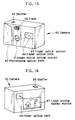
- FIG. 18 is a front perspective view illustrative of an uncovered personal computer in which the zoom lens system of the invention is incorporated in the form of an objective optical system.
- FIG. 19 is a sectional view illustrative of a phototaking optical system in a personal computer.
- FIG. 20 is a side view of FIG. 18 .
- FIGS. 21 ( a ), 21 ( b ) and 22 ( c ) are a front, a side and a sectional view of a portable telephone handset, respectively, in which the zoom lens system of the invention is incorporated in the form of an objective optical system.
- Lens sections of Examples 1 to 10 at their wide-angle ends (a), intermediate settings (b) and telephoto ends (c) are shown in FIGS. 1 to 10 . Numerical data on each example will be enumerated later.
- This example is directed to a zoom lens system which, as shown in FIG. 1, a first lens group G 1 , a second lens group G 2 , a third lens group G 3 and a fourth lens group G 4 , with a fixed stop S is located between the second lens group G 2 and the third lens group G 3 .
- the first lens group G 1 is a fixed lens group and, for zooming from the wide-angle end to the telephoto end of the system, the second lens group G 2 moves toward an image plane I while the third and fourth lens groups G 3 and G 4 move toward the object side.
- An optical path splitter, an optical filter, etc. are located between the fourth lens group G 4 and the image plane I. This is also true of the following examples.
- the first lens group G 1 consists of a doublet composed of a negative meniscus lens convex on the object side and a positive meniscus lens convex on the object side, and a positive meniscus lens convex on the object side, three in all.
- the second lens group G 2 consists of two negative meniscus lenses, each convex on the object side, and a doublet composed of a double-concave lens and a positive meniscus lens convex on the object side, four in all.
- the third lens group G 3 consists of two double-convex lenses and a double-concave lens, three in all.
- the fourth lens group G 4 consists of a doublet composed of a negative meniscus lens convex on the image side and a positive meniscus lens convex on the image side, and two double-convex lenses, four in all. Two aspherical surfaces are used, one for the object-side surface of the second double-convex lens in the third lens group G 3 and another for the surface located nearest to the image side in the fourth lens group G 4 .
- the first lens group G 1 consists of a doublet composed of a negative meniscus lens convex on the object side and a positive meniscus lens convex on the object side, and a positive meniscus lens convex on the object side, three in all.
- the second lens group G 2 consists of two negative meniscus lenses, each convex on the object side, and a doublet composed of a double-concave lens and a positive meniscus lens convex on the object side, four in all.
- the third lens group G 3 consists of two double-convex lenses and a double-concave lens, three in all.
- the fourth lens group G 4 consists of a doublet composed of a double-concave lend and a double-convex lens and two double-convex lenses, four in all. Two aspherical surfaces are used, one for the object-side surface of the second double-convex lens in the third lens group G 3 and another for the surface located nearest to the image side in the fourth lens group G 4 .
- the first lens group G 1 consists of a doublet composed of a negative meniscus lens convex on the object side and a positive meniscus lens convex on the object side, and a positive meniscus lens convex on the object side, three in all.
- the second lens group G 2 consists of a negative meniscus lens convex on the object side, a double-concave lens and a doublet composed of a double-concave lens and a positive meniscus lens convex on the object side, four in all.
- the third lens group G 3 consists of a positive meniscus lens convex on the object side, a double-convex lens and a negative meniscus lens convex on the object side, three in all.
- the fourth lens group G 4 consists of a doublet composed of a negative meniscus lens convex on the image side and a positive meniscus lens convex on the image side, and four double-convex lenses, four in all. Two aspherical surfaces are used, one for the object-side surface of the double-convex lens in the third lens group G 3 and another for the surface located nearest to the image side in the fourth lens group G 4 .
- the first lens group G 1 consists of a doublet composed of a negative meniscus lens convex on the object side and a positive meniscus lens convex on the object side, and a positive meniscus lens convex on the object side, three in all.
- the second lens group G 2 consists of a negative meniscus lens convex on the object side, a double-concave lens and a doublet composed of a double-concave lens and a double-convex lens, four in all.
- the third lens group G 3 consists of a double-convex lens, a positive meniscus lens convex on the object side and a negative meniscus lens convex on the object side, three in all.
- the fourth lens group G 4 consists of a doublet composed of a double-concave lens and a double-convex lens and two double-convex lenses, four in all. Two aspherical surfaces are used, one for the object-side surface of the positive meniscus lens convex on the object side in the third lens group G 3 and another for the surface located nearest to the image side in the fourth lens group G 4 .
- the first lens group G 1 consists of a doublet composed of a negative meniscus lens convex on the object side and a positive meniscus lens convex on the object side, and a positive meniscus lens convex on the object side, three in all.
- the second lens group G 2 consists of a negative meniscus lens convex on the object side, a double-concave lens and a doublet composed of a negative meniscus lens convex on the object side and a plano-convex lens, four in all.
- the third lens group G 3 consists of two double-convex lenses and a negative meniscus lens convex on the image side, three in all.
- the fourth lens group G 4 consists of a doublet composed of a negative meniscus lens convex on the image side and a positive meniscus lens convex on the image side, a double-convex lens and a positive meniscus lens convex on the image side, four in all.
- Three aspherical surfaces are used, one for the image-side surface of the double-concave lens in the second lens group G 2 , one for the surface located nearest to the object side in the third lens group G 3 , and one for the object-side surface of the positive meniscus lens located nearest to the image side in the fourth lens group G 4 .
- the first lens group G 1 consists of a doublet composed of a positive meniscus lens convex on the object side and a positive meniscus lens convex on the object side, and a positive meniscus lens convex on the object side, three in all.
- the second lens group G 2 consists of a negative meniscus lens convex on the object side, a doublet composed of a double-concave lens and a negative meniscus lens convex on the object side and a negative meniscus lens convex on the image side, four in all.
- the third lens group G 3 consists of a positive meniscus lens convex on the object side, a double-convex lens and a negative meniscus lens convex on the object side, three in all.
- the fourth lens group G 4 consists of a doublet composed of a negative meniscus lens convex on the image side and a positive meniscus lens convex on the image side, a double-convex lens and a positive meniscus lens convex on the object side.
- Two aspherical surfaces are used, one for the object-side surface of the double-convex lens in the third lens group G 3 and another for the object-side surface of the positive meniscus lens convex on the object side in the fourth lens group G 4 .
- the first lens group G 1 consists of a doublet composed of a negative meniscus lens convex on the object side and a positive meniscus lens convex on the object side, and a positive meniscus lens convex on the object side, three in all.
- the second lens group G 2 consists of a negative meniscus lens convex on the object side, a double-concave lens and a doublet composed of a double-concave lens and a double-convex lens, four in all.
- the third lens group G 3 consists of a positive meniscus lens convex on the object side, a double-convex lens and a negative meniscus lens convex on the object side, three in all.
- the fourth lens group G 4 consists of a doublet composed of a negative meniscus lens convex on the image side and a positive meniscus lens convex on the image side and two double-convex lenses, four in all. Two aspherical surfaces are used, one for the object-side surface of the double-convex lens in the third lens group G 3 and another for the surface nearest to the image side in the fourth lens group G 4 .
- the first lens group G 1 consists of doublet composed of a negative meniscus lens convex on the object side and a positive meniscus lens convex on the object side and a positive meniscus lens convex on the object side, three in all.
- the second lens group G 2 consists of a negative meniscus lens convex on the object side, a plano-double-concave lens and a doublet composed of a double-concave lens and a plano-convex lens, four in all.
- the third lens group G 3 consists of a positive meniscus lens convex on the object side, a double-convex lens and a negative meniscus lens convex on the object side, three in all.
- the fourth lens group G 4 consists of a doublet composed of a negative meniscus lens convex on the image side and a positive meniscus lens convex on the image side, and two double-convex lenses, four in all. Two aspherical surfaces are used, one for the object-side surface of the double-convex lens in the third lens group G 3 and another for the surface nearest to the image side in the fourth lens group G 4 .
- the first lens group G 1 consists of a doublet composed of a negative meniscus lens convex on the object side and a positive meniscus lens convex on the object side, and a positive meniscus lens convex on the object side, three in all.
- the second lens group G 2 consists of two negative meniscus lenses, each convex on the object side, and a doublet composed of a double-concave lens and a positive meniscus lens convex on the object side, four in all.
- the third lens group G 3 consists of a positive meniscus lens convex on the object side, a double-convex lens and a negative meniscus lens convex on the object side, three in all.
- the fourth lens group G 4 consists of a doublet composed of a negative meniscus lens convex on the image side and a positive meniscus lens convex on the image side, and a double-convex lens, three in all. Two aspherical surfaces are used, one for the object-side surface of the double-convex lens in the third lens group G 3 and another for the surface nearest to the image side in the fourth lens group G 4 .
- the first lens group G 1 consists of a doublet composed of a negative meniscus lens convex on the object side and a positive meniscus lens convex on the object side, and a positive meniscus lens convex on the object side, three in all.
- the second lens group G 2 consists of a negative meniscus lens convex on the object side, a double-concave lens and a doublet composed of a double-concave lens and a double-convex lens, four in all.
- the third lens group G 3 consists of a positive meniscus lens convex on the object side, a double-convex lens and a negative meniscus lens convex on the object side, three in all.
- the fourth lens group G 4 consists of a doublet composed of a negative meniscus lens convex on the image side and a positive meniscus lens convex on the image side, and a double-convex lens, three in all. Two aspherical surfaces are used, one for the object-side surface of the double-convex lens in the third lens group G 3 and another for the object-side surface of the double-convex lens in the fourth lens group G 4 .
- f is a focal length of the overall system
- F NO is an F-number
- ⁇ is a half field angle
- L is a distance from the final lens surface to the image plane
- r 1 , r 2 , . . . are radii of curvature of lens surfaces
- d 1 , d 2 , . . . are separations between adjacent lens surfaces
- n d1 , n d2 , . . . are d-line indices of refraction of lenses
- v d1 , v d2 , . . . are d-line Abbe's numbers of lenses.
- r is a radius of paraxial curvature
- K is a conical coefficient
- a 4 , A 6 , A 8 and A 10 are fourth-, sixth-, eighth- and tenth-order aspherical coefficients, respectively.
- FIGS. 11 ( a ), 11 ( b ) and 11 ( c ) are aberration diagrams of Example 1 upon focused at infinity.
- FIGS. 12 ( a ), 12 ( b ) and 12 ( c ) are aberration diagrams of Example 1 upon focused with the fourth lens group 4 at an object distance of 300 mm.
- SA, AS, DT and CC stand for spherical aberration, astigmatism, distortion and chromatic aberration of magnification, respectively, at the wide-angle ends (a), intermediate settings (b) and telephoto ends (c).
- “IH” in these drawings represents an image height.
- the negative lens that is located in the second lens group G 2 and has a partial dispersion ratio satisfying condition (8) is a lens defined by the eighth and ninth surfaces in each of Examples 1 to 5 and Examples 7 to 10 (the second lens in the second lens group G 2 ), and by the eleventh and twelfth surfaces in Example 6 (the fourth lens in the second lens group G 2 ).
- the positive lens that is located in the third lens group G 3 , and the fourth lens group G 4 and has a partial dispersion ratio satisfying condition (9) is a lens defined by the fourteenth and fifteenth surfaces in each of Examples 1 to 10 (the first lens in the third lens group G 3 ).
- the zoom lens system of the invention may be used on various phototaking devices wherein images are phototaken on image pickup elements such as CCDs or silver-salt films, especially digital or video cameras, personal computers that are one example of information processors, and telephone handsets, especially convenient-to-carry portable telephone sets, etc., as explained below with reference to some specific examples.
- image pickup elements such as CCDs or silver-salt films, especially digital or video cameras, personal computers that are one example of information processors, and telephone handsets, especially convenient-to-carry portable telephone sets, etc., as explained below with reference to some specific examples.
- FIGS. 13 to 15 are conceptual representations of an arrangement wherein the zoom lens system of the invention is incorporated in a phototaking optical system in a digital camera.
- FIGS. 13 and 14 are a front and a rear perspective view showing the appearance of a digital camera 40 , respectively, and
- FIG. 15 is a sectional view of the construction of the digital camera 40 .
- the digital camera 40 comprises a phototaking optical system 41 having a phototaking optical path 42 , a finder optical system 43 having a finder optical path 44 , a shutter 45 , a flash 46 and a liquid crystal display monitor 47 .
- phototaking occurs through the phototaking optical system 41 , e.g., the zoom lens system according to Example 1.
- An object image formed through the phototaking optical system 41 is formed on an image pickup surface of a CCD 49 via filters F such as a low-pass filter and an infrared cut filter.
- An object image received at CCD 49 is displayed as an electronic image on the liquid crystal display monitor 47 via a processing means 51 , said monitor 47 being mounted on the back side of the camera.
- the processing means 51 may be connected with a recording means 52 for recording the phototaken electronic image. It is here noted that the recording means 52 may be located separately from the processing means 51 . For this recording means 52 , it is acceptable to use a floppy disk or memory card or an MO that can write or read information electronically. Alternatively, a silver-salt film may be used in place of CCD 49 to set up a silver-salt camera.
- a finder objective optical system 53 is mounted on the finder optical path 44 .
- An object image formed through the finder objective optical system 53 is formed on a field frame 57 of a Porro prism 55 that is an image-erecting member.
- an eyepiece optical system 59 In the rear of this Porro prism 55 , there is located an eyepiece optical system 59 for guiding the erected image to a viewer's eyeball E.
- Two cover members 50 are provided, one on the entrance side of the phototaking optical system 41 and finder objective optical system 53 and another on the exit side of an eyepiece optical system 59 .
- the phototaking optical system 41 is constructed of the zoom lens system of the invention which has high zoom ratios at the wide-angle end with well-corrected aberrations, is fast, and has a back focus large-enough for accommodation of filters, etc.
- high performance and cost reductions are achievable.
- FIG. 16 is a conceptual representation of an arrangement wherein the zoom lens system of the invention is incorporated in an objective optical system in the phototaking portion of a video camera.
- the zoom lens system according to Example 1 is used for a phototaking objective optical system 61 located on a phototaking optical path.
- an image-forming light beam is separated into beams R, G and B through an R-reflecting mirror 63 R and a G-reflecting mirror 63 G in a color separation prism 62 located on a back focus side, so that object images separated into R, G and B are formed on an R-receiving CCD 64 R, a G-receiving CCD 64 G and a B-receiving CCD 64 B, each provided with a cover glass 64 .
- the color-separated object images received at CCDs 64 R, 64 G and 64 B are displayed as a color electronic image on a liquid crystal display plate 66 through a processing means 65 .
- This processing means 65 also controls a recording means 70 (e.g., a video tape, a CD or a DVD) for recording a sound from a microphone 68 and object images phototaken through CCDs 64 R, 64 G and 64 B as electronic information.
- the image displayed on the liquid crystal display plate 66 is illuminated by a backlight and then guided via an eyepiece optical system 69 to a viewer's eyeball E.
- Two cover members 50 are provided, one on the entrance side of the phototaking objective optical system 61 and another on the exit side of the eyepiece optical system 69 .
- the phototaking objective optical system 61 is constructed of the zoom lens system of the invention which has high zoom ratios at the wide-angle end with well-corrected aberrations, is fast, and has a back focus large-enough for accommodation of filters, etc.
- the large back focus ensures a high degree of freedom in locating the color separation prism 62 on the back focus side.
- FIG. 17 ( a ) is a conceptual representation of an arrangement wherein the zoom lens system of the invention is incorporated in an objective optical system in a single-lens reflex camera.
- the zoom lens system according to Example 1 is used as an objective optical system 71 .
- an image-forming beam is separated by a half-silvered mirror (e.g., a beam splitter) 72 located on the back focus side into two light beams, one for a phototaking optical path and another for a finder optical path.
- a half-silvered mirror e.g., a beam splitter
- filters F such as a low-pass filter and an infrared cut filter and a CCD 73 , so that an object image can be formed on an image pickup surface of CCD 73 through the filters F.
- a screen mat 74 is located on a primary image plane formed at a position conjugate with the image pickup surface. This primary image is reflected at a plane mirror 75 and then relayed as a secondary image through a relay optical system 76 while it is erected. Then, the secondary image is guided through an eyepiece 77 to a viewer's eyeball E.
- the plane mirror 75 and relay optical system 76 may be replaced by a concave mirror prism 78 having positive power, as illustrated in FIG. 17 ( b ).
- a concave mirror prism 78 having positive power, as illustrated in FIG. 17 ( b ).
- the concave mirror prism 78 it is acceptable to impart powers to the entrance and exit surfaces. It is also acceptable to construct the reflecting surface of not only a rotationally symmetric surface (e.g., a spherical or aspherical surface) but also a rotationally asymmetric surface such as an anamorphic or free-form surface. It is further acceptable to use a silver-salt film in place of CCD 73 , thereby sitting up a silver-salt camera.
- FIGS. 18 to 20 Shown in FIGS. 18 to 20 is a personal computer that is one example of the information processor in which the zoom lens system of the invention is incorporated in the form of an objective optical system.
- FIG. 18 is a front perspective view of an uncovered personal computer 300
- FIG. 19 is a sectional view of a phototaking optical system 303 mounted on the personal computer 300
- FIG. 20 is a side view of FIG. 18 .
- the personal computer 300 comprises a keyboard 301 for allowing an operator to enter information therein from outside, information processing and recording means (not shown), a monitor 302 for displaying the information to the operator and a phototaking optical system 303 for phototaking an image of the operator per se and images of operator's surroundings.
- the monitor 302 used herein may be a transmission type liquid crystal display device designed to be illuminated by a backlight (not shown) from the back side, a reflection type liquid crystal display device designed to display images by reflecting light from the front side, a CRT display or the like.
- the phototaking optical system 303 is built in a right upper portion of monitor 302 . However, it is to be understood that the phototaking optical system 303 may be positioned somewhere on the periphery of monitor 302 or keyboard 301 .
- the phototaking optical system 303 includes on a phototaking optical path 304 an objective lens system 112 comprising the zoom lens system of the invention (roughly illustrated) and an image pickup element chip 162 for receiving an image. These are built in the personal computer 300 .
- an IR cut filter out of members F such as an optical filter is additionally pasted onto the image pickup element chip 162 to construct an integral image pickup unit 160 .
- This image pickup unit 160 can be fitted in the rear end of a lens barrel 113 of the objective lens system 112 in one-touch simple operation, so that centering and alignment of the objective lens system 112 with respect to the image pickup element chip 162 can be dispensed with to make assembly simple.
- a cover glass 114 for protection of the objective lens system 112 . It is here to be understood that the zoom lens driving mechanism in the lens barrel 113 is not shown.
- An object image received at the image pickup element chip 162 is entered from a terminal 166 in the processing means in the personal computer 300 , and displayed as an electronic image on the monitor 302 .
- Shown in FIG. 18 as an example is a phototaken image 305 of the operator. It is possible to display the image 305 , etc. on a personal computer at the other end on a remote place via an internet or telephone line.
- FIG. 21 Illustrated in FIG. 21 is a telephone handset that is one example of the information processor in which the zoom lens system of the invention is built in the form of a phototaking optical system, especially a convenient-to-carry portable telephone handset.
- FIG. 21 ( a ) is a front view of a portable telephone handset 400
- FIG. 21 ( b ) is a side view of handset 400
- FIG. 21 ( c ) is a sectional view of a phototaking optical system 405 .
- FIGS. 21 ( a ) is a front view of a portable telephone handset 400
- FIG. 21 ( b ) is a side view of handset 400
- FIG. 21 ( c ) is a sectional view of a phototaking optical system 405 .
- the telephone handset 400 comprises a microphone portion 401 for entering an operator's voice therein as information, a speaker portion 402 for producing a voice of a person on the other end, an input dial 403 allowing the operator to enter information therein, a monitor 404 for displaying phototaken images of the operator and the person on the other end and information such as telephone numbers, a phototaking optical system 405 , an antenna 406 for transmitting and receiving communication waves and a processing means (not shown) for processing image information, communication information, input signals, etc.
- the monitor 404 used herein is a liquid crystal display device. The arrangement of these parts is not necessarily limited to that illustrated.
- the phototaking optical system 405 includes on a phototaking optical path 407 an objective lens system 112 comprising the zoom lens system (roughly illustrated) of the invention and an image pickup element chip 162 for receiving an object image. These are built in the telephone handset 400 .
- an IR cut filter out of members F such as an optical filter is additionally pasted onto the image pickup element chip 162 to construct an integral image pickup unit 160 .
- This image pickup unit 160 can be fitted in the rear end of a lens barrel 113 of the objective lens system 112 in one-touch simple operation, so that centering and alignment of the objective lens system 112 with respect to the image pickup element chip 162 can be dispensed with to make assembly simple.
- a cover glass 114 for protection of the objective lens system 112 . It is here to be understood that the zoom lens driving mechanism in the lens barrel 113 is not shown.
- the object image received at the image pickup element chip 162 is entered from a terminal 166 in a processing means (not shown), and displayed as an electronic image on the monitor 404 and/or a monitor on the other end.
- the processing means includes a signal processing function of converting information about the object image received at the image pickup element chip 162 to transmittable signals.
Landscapes
- Physics & Mathematics (AREA)
- General Physics & Mathematics (AREA)
- Optics & Photonics (AREA)
- Lenses (AREA)
Priority Applications (1)
| Application Number | Priority Date | Filing Date | Title |
|---|---|---|---|
| US10/132,704 US6646814B2 (en) | 1999-03-09 | 2002-04-26 | Zoom lens, and image pickup device using the same |
Applications Claiming Priority (4)
| Application Number | Priority Date | Filing Date | Title |
|---|---|---|---|
| JP6189799 | 1999-03-09 | ||
| JP11-061897 | 1999-03-09 | ||
| JP2000-017311 | 2000-01-26 | ||
| JP2000017311A JP4153640B2 (ja) | 1999-03-09 | 2000-01-26 | ズームレンズ及び撮像装置 |
Related Child Applications (1)
| Application Number | Title | Priority Date | Filing Date |
|---|---|---|---|
| US10/132,704 Continuation US6646814B2 (en) | 1999-03-09 | 2002-04-26 | Zoom lens, and image pickup device using the same |
Publications (1)
| Publication Number | Publication Date |
|---|---|
| US6414799B1 true US6414799B1 (en) | 2002-07-02 |
Family
ID=26402989
Family Applications (2)
| Application Number | Title | Priority Date | Filing Date |
|---|---|---|---|
| US09/522,038 Expired - Lifetime US6414799B1 (en) | 1999-03-09 | 2000-03-09 | Zoom lens, and image pickup device using the same |
| US10/132,704 Expired - Lifetime US6646814B2 (en) | 1999-03-09 | 2002-04-26 | Zoom lens, and image pickup device using the same |
Family Applications After (1)
| Application Number | Title | Priority Date | Filing Date |
|---|---|---|---|
| US10/132,704 Expired - Lifetime US6646814B2 (en) | 1999-03-09 | 2002-04-26 | Zoom lens, and image pickup device using the same |
Country Status (2)
| Country | Link |
|---|---|
| US (2) | US6414799B1 (ja) |
| JP (1) | JP4153640B2 (ja) |
Cited By (9)
| Publication number | Priority date | Publication date | Assignee | Title |
|---|---|---|---|---|
| US6538825B1 (en) * | 2001-04-12 | 2003-03-25 | Industrial Technology Research Institute | Zoom lens |
| US20030099043A1 (en) * | 2001-10-30 | 2003-05-29 | Nidec Copal Corporation | Zoom lens |
| US20040161228A1 (en) * | 2002-12-27 | 2004-08-19 | Norihiro Nanba | Zoom lens system and camera having the same |
| US7123421B1 (en) | 2005-04-22 | 2006-10-17 | Panavision International, L.P. | Compact high performance zoom lens system |
| US20080247054A1 (en) * | 2005-10-31 | 2008-10-09 | Ukyo Tomioka | Zoom lens |
| US20090296231A1 (en) * | 2008-05-30 | 2009-12-03 | Canon Kabushiki Kaisha | Zoom lens and image pickup apparatus including the same |
| EP2144108A1 (en) * | 2008-07-08 | 2010-01-13 | Ricoh Company, Ltd. | Zoom lens unit, imaging apparatus and portable information terminal device |
| DE102010029089A1 (de) * | 2010-05-18 | 2011-11-24 | Carl Zeiss Ag | Optisches System zur Kalibrierung einer Lichtquelle |
| US20130258496A1 (en) * | 2010-12-07 | 2013-10-03 | Haruo Sato | Zoom lens, imaging device and method for manufacturing the zoom lens |
Families Citing this family (16)
| Publication number | Priority date | Publication date | Assignee | Title |
|---|---|---|---|---|
| JP3566698B2 (ja) * | 2002-01-17 | 2004-09-15 | キヤノン株式会社 | ファインダー及びそれを用いた光学機器 |
| JP4712318B2 (ja) * | 2003-06-11 | 2011-06-29 | オリンパス株式会社 | 結像光学系及びそれを用いた電子機器 |
| JP4585794B2 (ja) * | 2004-05-31 | 2010-11-24 | キヤノン株式会社 | ズームレンズ及びそれを有する撮像装置 |
| JP4731834B2 (ja) * | 2004-06-04 | 2011-07-27 | キヤノン株式会社 | ズームレンズ及びそれを有する撮像装置 |
| JP2006184416A (ja) * | 2004-12-27 | 2006-07-13 | Konica Minolta Photo Imaging Inc | 撮影光学系および撮像装置 |
| US7734169B2 (en) * | 2006-01-10 | 2010-06-08 | Olympus Imaging Corp. | Camera |
| JP5111789B2 (ja) * | 2006-06-08 | 2013-01-09 | オリンパスイメージング株式会社 | ズームレンズ及びそれを備えた電子撮像装置 |
| JP5072447B2 (ja) * | 2007-06-18 | 2012-11-14 | キヤノン株式会社 | ズームレンズ及びそれを有する撮像装置 |
| JP5197262B2 (ja) * | 2008-09-16 | 2013-05-15 | キヤノン株式会社 | ズームレンズ及びそれを有する撮像装置 |
| JP2010217478A (ja) | 2009-03-17 | 2010-09-30 | Olympus Imaging Corp | ズームレンズ及びそれを備える撮像装置 |
| JP5460228B2 (ja) * | 2009-04-02 | 2014-04-02 | キヤノン株式会社 | ズームレンズ及びそれを有する撮像装置 |
| US8736970B2 (en) * | 2009-11-20 | 2014-05-27 | Samsung Electronics Co., Ltd | Optical system of zoom lens with image stabilization |
| RU2423732C1 (ru) | 2009-11-20 | 2011-07-10 | Корпорация "САМСУНГ ЭЛЕКТРОНИКС Ко., Лтд." | Оптическая система объектива-трансфокатора со стабилизацией изображения |
| JP6245507B2 (ja) * | 2013-09-11 | 2017-12-13 | 株式会社リコー | ズームレンズ、カメラおよび携帯情報端末装置 |
| JP2016161648A (ja) * | 2015-02-27 | 2016-09-05 | 株式会社タムロン | 光学系及び撮像装置 |
| JP2018189839A (ja) * | 2017-05-09 | 2018-11-29 | オリンパス株式会社 | 変倍光学系及びそれを備えた撮像装置 |
Citations (3)
| Publication number | Priority date | Publication date | Assignee | Title |
|---|---|---|---|---|
| US5315438A (en) * | 1990-12-12 | 1994-05-24 | Olympus Optical Co., Ltd. | Zoom lens system |
| US5886828A (en) * | 1996-12-19 | 1999-03-23 | Samsung Aerospace Industries, Ltd. | Zoom lens system |
| US5923478A (en) * | 1996-06-14 | 1999-07-13 | Minolta Co., Ltd. | Zoom lens system |
Family Cites Families (8)
| Publication number | Priority date | Publication date | Assignee | Title |
|---|---|---|---|---|
| JPS5913212A (ja) | 1982-07-14 | 1984-01-24 | Canon Inc | ズ−ムレンズ |
| JPH07107577B2 (ja) | 1986-07-24 | 1995-11-15 | オリンパス光学工業株式会社 | ズ−ムレンズ |
| JP3085823B2 (ja) | 1993-06-07 | 2000-09-11 | 松下電器産業株式会社 | 非球面ズームレンズとそれを用いたビデオカメラ |
| JP3431996B2 (ja) * | 1994-05-18 | 2003-07-28 | オリンパス光学工業株式会社 | ズームレンズ |
| JPH0882743A (ja) | 1994-09-12 | 1996-03-26 | Canon Inc | リヤーフォーカス式のズームレンズ |
| US6226130B1 (en) * | 1996-04-09 | 2001-05-01 | Canon Kabushiki Kaisha | Zoom lens |
| JP3686178B2 (ja) | 1996-08-23 | 2005-08-24 | オリンパス株式会社 | ズームレンズ |
| JP3640366B2 (ja) * | 1996-08-29 | 2005-04-20 | フジノン株式会社 | ズームレンズ |
-
2000
- 2000-01-26 JP JP2000017311A patent/JP4153640B2/ja not_active Expired - Fee Related
- 2000-03-09 US US09/522,038 patent/US6414799B1/en not_active Expired - Lifetime
-
2002
- 2002-04-26 US US10/132,704 patent/US6646814B2/en not_active Expired - Lifetime
Patent Citations (3)
| Publication number | Priority date | Publication date | Assignee | Title |
|---|---|---|---|---|
| US5315438A (en) * | 1990-12-12 | 1994-05-24 | Olympus Optical Co., Ltd. | Zoom lens system |
| US5923478A (en) * | 1996-06-14 | 1999-07-13 | Minolta Co., Ltd. | Zoom lens system |
| US5886828A (en) * | 1996-12-19 | 1999-03-23 | Samsung Aerospace Industries, Ltd. | Zoom lens system |
Non-Patent Citations (5)
| Title |
|---|
| Patent Abstracts of Japan, Aspherical Zoom Lens and Video Camera Using the Same, Dec. 22, 1994, re JP-A-6-347697. |
| Patent Abstracts of Japan, Zoom Lens of Rear Focus Type, Mar. 26, 1996, re JP-A-8-082743. |
| Patent Abstracts of Japan, Zoom Lens, Feb. 8, 1988, re JP-A-63-29718. |
| Patent Abstracts of Japan, Zoom Lens, Jan. 24, 1984, re JP-A-59-13212. |
| Patent Abstracts of Japan, Zoom Lens, Mar. 6, 1998, re JP-A-10-062687. |
Cited By (18)
| Publication number | Priority date | Publication date | Assignee | Title |
|---|---|---|---|---|
| US6538825B1 (en) * | 2001-04-12 | 2003-03-25 | Industrial Technology Research Institute | Zoom lens |
| US20030099043A1 (en) * | 2001-10-30 | 2003-05-29 | Nidec Copal Corporation | Zoom lens |
| US6757111B2 (en) * | 2001-10-30 | 2004-06-29 | Nidec Copal Corporation | Zoom lens |
| US20040161228A1 (en) * | 2002-12-27 | 2004-08-19 | Norihiro Nanba | Zoom lens system and camera having the same |
| US6931207B2 (en) | 2002-12-27 | 2005-08-16 | Canon Kabushiki Kaisha | Zoom lens system and camera having the same |
| US7123421B1 (en) | 2005-04-22 | 2006-10-17 | Panavision International, L.P. | Compact high performance zoom lens system |
| US20060238887A1 (en) * | 2005-04-22 | 2006-10-26 | Panavision International, L.P. | Compact high performance zoom lens system |
| US7554747B2 (en) * | 2005-10-31 | 2009-06-30 | Fujinon Corporation | Zoom lens |
| US20080247054A1 (en) * | 2005-10-31 | 2008-10-09 | Ukyo Tomioka | Zoom lens |
| US20090296231A1 (en) * | 2008-05-30 | 2009-12-03 | Canon Kabushiki Kaisha | Zoom lens and image pickup apparatus including the same |
| US7864445B2 (en) | 2008-05-30 | 2011-01-04 | Canon Kabushiki Kaisha | Zoom lens and image pickup apparatus including the same |
| EP2144108A1 (en) * | 2008-07-08 | 2010-01-13 | Ricoh Company, Ltd. | Zoom lens unit, imaging apparatus and portable information terminal device |
| US20100007967A1 (en) * | 2008-07-08 | 2010-01-14 | Kazuyasu Ohashi | Zoom lens unit, imaging apparatus and portable information terminal device |
| US7855842B2 (en) | 2008-07-08 | 2010-12-21 | Ricoh Company, Ltd. | Zoom lens unit, imaging apparatus and portable information terminal device |
| DE102010029089A1 (de) * | 2010-05-18 | 2011-11-24 | Carl Zeiss Ag | Optisches System zur Kalibrierung einer Lichtquelle |
| DE102010029089B4 (de) * | 2010-05-18 | 2019-08-29 | Carl Zeiss Ag | Optisches System zur Kalibrierung einer Lichtquelle |
| US20130258496A1 (en) * | 2010-12-07 | 2013-10-03 | Haruo Sato | Zoom lens, imaging device and method for manufacturing the zoom lens |
| US9341829B2 (en) * | 2010-12-07 | 2016-05-17 | Nikon Corporation | Zoom lens, imaging device and method for manufacturing the zoom lens |
Also Published As
| Publication number | Publication date |
|---|---|
| US20030072086A1 (en) | 2003-04-17 |
| US6646814B2 (en) | 2003-11-11 |
| JP2000321499A (ja) | 2000-11-24 |
| JP4153640B2 (ja) | 2008-09-24 |
Similar Documents
| Publication | Publication Date | Title |
|---|---|---|
| US6414799B1 (en) | Zoom lens, and image pickup device using the same | |
| US6594087B2 (en) | Zoom lens | |
| US6744571B2 (en) | Zoom lens system | |
| US7079328B2 (en) | Path-bending zoom optical system | |
| US6535339B1 (en) | Image pickup system | |
| US7190529B2 (en) | Zoom lens | |
| US6614599B1 (en) | Zoom lens system, and image pickup system using the same | |
| US7110187B2 (en) | Zoom lens and electronic imaging apparatus using the same | |
| JP4766933B2 (ja) | 光路折り曲げ式ズームレンズ及びそれを備えた撮像装置 | |
| US20110157715A1 (en) | Zoom lens and image pickup apparatus including the same | |
| JP4766929B2 (ja) | 光路折り曲げ式ズームレンズを備えた撮像装置 | |
| US7872809B2 (en) | Optical system and imaging system incorporating it | |
| US6362925B1 (en) | Lens group zoom lens system, and display device having phototaking function | |
| US8503090B2 (en) | Zoom optical system, and imaging apparatus incorporating the same | |
| US6359738B1 (en) | Two-group zoom lens system and display device having phototaking function | |
| US7446948B2 (en) | Zoom optical system and imaging system using the same | |
| JP5722181B2 (ja) | 光路反射型ズームレンズを備えた撮像装置 | |
| JP2004333769A (ja) | ズームレンズ及びそれを用いた撮像機器 | |
| US6865032B2 (en) | Real image type finder optical system, and imaging system comprising the same | |
| US11314065B2 (en) | Zoom lens and image pickup apparatus | |
| JP5025821B2 (ja) | ズームレンズ及びズームレンズと撮像素子を備えたカメラ | |
| USRE39899E1 (en) | Image pickup system | |
| JP5784439B2 (ja) | 光路反射型ズームレンズを備えた撮像装置 | |
| JP2013050675A (ja) | 光路反射型ズームレンズを備えた撮像装置 |
Legal Events
| Date | Code | Title | Description |
|---|---|---|---|
| AS | Assignment |
Owner name: OLYMPUS OPTICAL CO., LTD., JAPAN Free format text: ASSIGNMENT OF ASSIGNORS INTEREST;ASSIGNORS:UZAWA, TSUTOMU;SUZUKI, MASAHIRO;REEL/FRAME:010632/0563;SIGNING DATES FROM 20000228 TO 20000303 |
|
| STCF | Information on status: patent grant |
Free format text: PATENTED CASE |
|
| FPAY | Fee payment |
Year of fee payment: 4 |
|
| FPAY | Fee payment |
Year of fee payment: 8 |
|
| FPAY | Fee payment |
Year of fee payment: 12 |
|
| AS | Assignment |
Owner name: OLYMPUS CORPORATION, JAPAN Free format text: CHANGE OF ADDRESS;ASSIGNOR:OLYMPUS CORPORATION;REEL/FRAME:039344/0502 Effective date: 20160401 |