US6371069B1 - Intake device - Google Patents
Intake device Download PDFInfo
- Publication number
- US6371069B1 US6371069B1 US09/684,956 US68495600A US6371069B1 US 6371069 B1 US6371069 B1 US 6371069B1 US 68495600 A US68495600 A US 68495600A US 6371069 B1 US6371069 B1 US 6371069B1
- Authority
- US
- United States
- Prior art keywords
- air intake
- manifold
- channels
- adjusting
- adjusting unit
- Prior art date
- Legal status (The legal status is an assumption and is not a legal conclusion. Google has not performed a legal analysis and makes no representation as to the accuracy of the status listed.)
- Expired - Fee Related
Links
Images


Classifications
-
- F—MECHANICAL ENGINEERING; LIGHTING; HEATING; WEAPONS; BLASTING
- F02—COMBUSTION ENGINES; HOT-GAS OR COMBUSTION-PRODUCT ENGINE PLANTS
- F02M—SUPPLYING COMBUSTION ENGINES IN GENERAL WITH COMBUSTIBLE MIXTURES OR CONSTITUENTS THEREOF
- F02M35/00—Combustion-air cleaners, air intakes, intake silencers, or induction systems specially adapted for, or arranged on, internal-combustion engines
- F02M35/10—Air intakes; Induction systems
- F02M35/10091—Air intakes; Induction systems characterised by details of intake ducts: shapes; connections; arrangements
- F02M35/10124—Ducts with special cross-sections, e.g. non-circular cross-section
-
- F—MECHANICAL ENGINEERING; LIGHTING; HEATING; WEAPONS; BLASTING
- F02—COMBUSTION ENGINES; HOT-GAS OR COMBUSTION-PRODUCT ENGINE PLANTS
- F02B—INTERNAL-COMBUSTION PISTON ENGINES; COMBUSTION ENGINES IN GENERAL
- F02B27/00—Use of kinetic or wave energy of charge in induction systems, or of combustion residues in exhaust systems, for improving quantity of charge or for increasing removal of combustion residues
- F02B27/02—Use of kinetic or wave energy of charge in induction systems, or of combustion residues in exhaust systems, for improving quantity of charge or for increasing removal of combustion residues the systems having variable, i.e. adjustable, cross-sectional areas, chambers of variable volume, or like variable means
-
- F—MECHANICAL ENGINEERING; LIGHTING; HEATING; WEAPONS; BLASTING
- F02—COMBUSTION ENGINES; HOT-GAS OR COMBUSTION-PRODUCT ENGINE PLANTS
- F02B—INTERNAL-COMBUSTION PISTON ENGINES; COMBUSTION ENGINES IN GENERAL
- F02B27/00—Use of kinetic or wave energy of charge in induction systems, or of combustion residues in exhaust systems, for improving quantity of charge or for increasing removal of combustion residues
- F02B27/02—Use of kinetic or wave energy of charge in induction systems, or of combustion residues in exhaust systems, for improving quantity of charge or for increasing removal of combustion residues the systems having variable, i.e. adjustable, cross-sectional areas, chambers of variable volume, or like variable means
- F02B27/0205—Use of kinetic or wave energy of charge in induction systems, or of combustion residues in exhaust systems, for improving quantity of charge or for increasing removal of combustion residues the systems having variable, i.e. adjustable, cross-sectional areas, chambers of variable volume, or like variable means characterised by the charging effect
- F02B27/0215—Oscillating pipe charging, i.e. variable intake pipe length charging
-
- F—MECHANICAL ENGINEERING; LIGHTING; HEATING; WEAPONS; BLASTING
- F02—COMBUSTION ENGINES; HOT-GAS OR COMBUSTION-PRODUCT ENGINE PLANTS
- F02B—INTERNAL-COMBUSTION PISTON ENGINES; COMBUSTION ENGINES IN GENERAL
- F02B27/00—Use of kinetic or wave energy of charge in induction systems, or of combustion residues in exhaust systems, for improving quantity of charge or for increasing removal of combustion residues
- F02B27/02—Use of kinetic or wave energy of charge in induction systems, or of combustion residues in exhaust systems, for improving quantity of charge or for increasing removal of combustion residues the systems having variable, i.e. adjustable, cross-sectional areas, chambers of variable volume, or like variable means
- F02B27/0226—Use of kinetic or wave energy of charge in induction systems, or of combustion residues in exhaust systems, for improving quantity of charge or for increasing removal of combustion residues the systems having variable, i.e. adjustable, cross-sectional areas, chambers of variable volume, or like variable means characterised by the means generating the charging effect
- F02B27/0231—Movable ducts, walls or the like
- F02B27/0236—Movable ducts, walls or the like with continuously variable adjustment of a length or width
-
- F—MECHANICAL ENGINEERING; LIGHTING; HEATING; WEAPONS; BLASTING
- F02—COMBUSTION ENGINES; HOT-GAS OR COMBUSTION-PRODUCT ENGINE PLANTS
- F02M—SUPPLYING COMBUSTION ENGINES IN GENERAL WITH COMBUSTIBLE MIXTURES OR CONSTITUENTS THEREOF
- F02M35/00—Combustion-air cleaners, air intakes, intake silencers, or induction systems specially adapted for, or arranged on, internal-combustion engines
- F02M35/10—Air intakes; Induction systems
- F02M35/10006—Air intakes; Induction systems characterised by the position of elements of the air intake system in direction of the air intake flow, i.e. between ambient air inlet and supply to the combustion chamber
- F02M35/10026—Plenum chambers
- F02M35/10052—Plenum chambers special shapes or arrangements of plenum chambers; Constructional details
-
- F—MECHANICAL ENGINEERING; LIGHTING; HEATING; WEAPONS; BLASTING
- F02—COMBUSTION ENGINES; HOT-GAS OR COMBUSTION-PRODUCT ENGINE PLANTS
- F02M—SUPPLYING COMBUSTION ENGINES IN GENERAL WITH COMBUSTIBLE MIXTURES OR CONSTITUENTS THEREOF
- F02M35/00—Combustion-air cleaners, air intakes, intake silencers, or induction systems specially adapted for, or arranged on, internal-combustion engines
- F02M35/10—Air intakes; Induction systems
- F02M35/10006—Air intakes; Induction systems characterised by the position of elements of the air intake system in direction of the air intake flow, i.e. between ambient air inlet and supply to the combustion chamber
- F02M35/10026—Plenum chambers
- F02M35/10065—Valves arranged in the plenum chamber
-
- F—MECHANICAL ENGINEERING; LIGHTING; HEATING; WEAPONS; BLASTING
- F02—COMBUSTION ENGINES; HOT-GAS OR COMBUSTION-PRODUCT ENGINE PLANTS
- F02M—SUPPLYING COMBUSTION ENGINES IN GENERAL WITH COMBUSTIBLE MIXTURES OR CONSTITUENTS THEREOF
- F02M35/00—Combustion-air cleaners, air intakes, intake silencers, or induction systems specially adapted for, or arranged on, internal-combustion engines
- F02M35/10—Air intakes; Induction systems
- F02M35/10006—Air intakes; Induction systems characterised by the position of elements of the air intake system in direction of the air intake flow, i.e. between ambient air inlet and supply to the combustion chamber
- F02M35/10072—Intake runners
-
- F—MECHANICAL ENGINEERING; LIGHTING; HEATING; WEAPONS; BLASTING
- F02—COMBUSTION ENGINES; HOT-GAS OR COMBUSTION-PRODUCT ENGINE PLANTS
- F02M—SUPPLYING COMBUSTION ENGINES IN GENERAL WITH COMBUSTIBLE MIXTURES OR CONSTITUENTS THEREOF
- F02M35/00—Combustion-air cleaners, air intakes, intake silencers, or induction systems specially adapted for, or arranged on, internal-combustion engines
- F02M35/10—Air intakes; Induction systems
- F02M35/10091—Air intakes; Induction systems characterised by details of intake ducts: shapes; connections; arrangements
- F02M35/10118—Air intakes; Induction systems characterised by details of intake ducts: shapes; connections; arrangements with variable cross-sections of intake ducts along their length; Venturis; Diffusers
-
- F—MECHANICAL ENGINEERING; LIGHTING; HEATING; WEAPONS; BLASTING
- F02—COMBUSTION ENGINES; HOT-GAS OR COMBUSTION-PRODUCT ENGINE PLANTS
- F02M—SUPPLYING COMBUSTION ENGINES IN GENERAL WITH COMBUSTIBLE MIXTURES OR CONSTITUENTS THEREOF
- F02M35/00—Combustion-air cleaners, air intakes, intake silencers, or induction systems specially adapted for, or arranged on, internal-combustion engines
- F02M35/10—Air intakes; Induction systems
- F02M35/10242—Devices or means connected to or integrated into air intakes; Air intakes combined with other engine or vehicle parts
- F02M35/10301—Flexible, resilient, pivotally or movable parts; Membranes
-
- F—MECHANICAL ENGINEERING; LIGHTING; HEATING; WEAPONS; BLASTING
- F02—COMBUSTION ENGINES; HOT-GAS OR COMBUSTION-PRODUCT ENGINE PLANTS
- F02M—SUPPLYING COMBUSTION ENGINES IN GENERAL WITH COMBUSTIBLE MIXTURES OR CONSTITUENTS THEREOF
- F02M35/00—Combustion-air cleaners, air intakes, intake silencers, or induction systems specially adapted for, or arranged on, internal-combustion engines
- F02M35/10—Air intakes; Induction systems
- F02M35/10314—Materials for intake systems
- F02M35/10321—Plastics; Composites; Rubbers
-
- F—MECHANICAL ENGINEERING; LIGHTING; HEATING; WEAPONS; BLASTING
- F02—COMBUSTION ENGINES; HOT-GAS OR COMBUSTION-PRODUCT ENGINE PLANTS
- F02M—SUPPLYING COMBUSTION ENGINES IN GENERAL WITH COMBUSTIBLE MIXTURES OR CONSTITUENTS THEREOF
- F02M35/00—Combustion-air cleaners, air intakes, intake silencers, or induction systems specially adapted for, or arranged on, internal-combustion engines
- F02M35/10—Air intakes; Induction systems
- F02M35/1034—Manufacturing and assembling intake systems
- F02M35/10347—Moulding, casting or the like
-
- F—MECHANICAL ENGINEERING; LIGHTING; HEATING; WEAPONS; BLASTING
- F02—COMBUSTION ENGINES; HOT-GAS OR COMBUSTION-PRODUCT ENGINE PLANTS
- F02M—SUPPLYING COMBUSTION ENGINES IN GENERAL WITH COMBUSTIBLE MIXTURES OR CONSTITUENTS THEREOF
- F02M35/00—Combustion-air cleaners, air intakes, intake silencers, or induction systems specially adapted for, or arranged on, internal-combustion engines
- F02M35/10—Air intakes; Induction systems
- F02M35/1034—Manufacturing and assembling intake systems
- F02M35/10354—Joining multiple sections together
- F02M35/1036—Joining multiple sections together by welding, bonding or the like
-
- F—MECHANICAL ENGINEERING; LIGHTING; HEATING; WEAPONS; BLASTING
- F02—COMBUSTION ENGINES; HOT-GAS OR COMBUSTION-PRODUCT ENGINE PLANTS
- F02M—SUPPLYING COMBUSTION ENGINES IN GENERAL WITH COMBUSTIBLE MIXTURES OR CONSTITUENTS THEREOF
- F02M35/00—Combustion-air cleaners, air intakes, intake silencers, or induction systems specially adapted for, or arranged on, internal-combustion engines
- F02M35/10—Air intakes; Induction systems
- F02M35/104—Intake manifolds
-
- Y—GENERAL TAGGING OF NEW TECHNOLOGICAL DEVELOPMENTS; GENERAL TAGGING OF CROSS-SECTIONAL TECHNOLOGIES SPANNING OVER SEVERAL SECTIONS OF THE IPC; TECHNICAL SUBJECTS COVERED BY FORMER USPC CROSS-REFERENCE ART COLLECTIONS [XRACs] AND DIGESTS
- Y02—TECHNOLOGIES OR APPLICATIONS FOR MITIGATION OR ADAPTATION AGAINST CLIMATE CHANGE
- Y02T—CLIMATE CHANGE MITIGATION TECHNOLOGIES RELATED TO TRANSPORTATION
- Y02T10/00—Road transport of goods or passengers
- Y02T10/10—Internal combustion engine [ICE] based vehicles
- Y02T10/12—Improving ICE efficiencies
Definitions
- the invention relates to an intake device containing a manifold, at least one air intake passage, an air intake tube for each passage connected to the respective air intake passage, and an adjusting unit.
- a device for the continuous variation of the length of the air intake tube of an internal combustion engine is disclosed in DE 36 08 310.
- the device comprises a stationary housing serving as a manifold in which a hollow cylindrical rotor body is disposed for rotation, the interior of which is connected to the air intake tube through a connection opening.
- Ducts separated from one another are defined between the outer circumference of the rotor body and the inner wall of the housing in the radial direction and between the sealing walls in the axial direction, and their effective length is determined by the rotational position of an outlet opening in the rotor body wall, which leads to the interior of the rotor body.
- each duct leads to an inlet opening of an intake passage leading to each cylinder of the internal combustion engine. Rotation of the rotor body varies the effective length of each duct according to the speed of the internal combustion engine at full load.
- the intake duct length is limited by the maximum possible rotor body circumference. Furthermore, upon issuing from the rotor body the fluid is extremely deflected.
- Another object of the invention is to provide an intake device which requires less deflection of the aspirated air than prior art devices.
- an air intake system for an internal combustion engine comprising an air intake manifold wherein a portion of the air intake manifold is divided into a plurality of air intake channels, each of the air intake channels being connected at one end to a respective air intake tube, and an adjusting member arranged to extend into the air intake manifold, the adjusting member being movable between a first position in which the air intake channels open to each other, whereby the effective lengths of the respective air intake tubes are shortened, and a second position in which the air intake channels are separated from each other, whereby the effective lengths of the respective air intake tubes are lengthened.
- an air intake apparatus comprising a manifold, at least one air intake channel in the manifold, an air intake tube connected to each respective air intake channel, and an adjusting unit, wherein the adjusting unit comprises a movable adjusting element which extends into the manifold; wherein the manifold, the at least one air intake passage, and the adjusting element are arranged axially parallel; and wherein the at least one air intake passage is formed by the manifold and the adjusting element.
- the intake device according to the invention is advantageously able to achieve great intake lengths with only slight deflection of the medium entering it and deliver it to an internal combustion engine.
- the intake device comprises a manifold which envelops a manifold chamber and forms a portion of the intake channels or passages.
- an adjusting unit extends which is mounted in guides provided therefor and which together with the manifold forms the intake channels or passages.
- the adjusting unit is mounted in the container in a sufficiently sealed or gas-tight manner that the individual intake passages are separate. The separation of the passages from one another can be accomplished by the interaction of the container with the adjusting unit.
- Each intake channel or passage which is to be understood as the adjustable length, is connected to an intake tube which has an invariable length.
- the intake tube opens into a cylinder of the internal combustion engine.
- the manifold, the adjusting unit and the intake channel or passage are arranged axially parallel.
- the adjusting unit of a straight embodiment can be constructed of a rigid or stiff material.
- the adjusting unit may either be made of flexible material or of material provided with solid inserts, or of stiff material with flexible inserts.
- the manifold can be made as a blow-molded plastic part, or in the case of complicated forms, it can be made by a core melting process.
- the adjusting unit has portions in which it forms a surface of contact with the manifold.
- the adjusting unit is arranged so that it is displaceable relative to the manifold.
- the manifold chamber is reduced and the effective passage length of the combined tubes and channels is lengthened.
- the manifold chamber in the manifold is increased and thus the air intake passage length is reduced.
- the external volume of the manifold is constant; the intake passage length is thus variable and can be adjusted to match the state of operation of the internal combustion engine.
- rotary or sliding sleeves can be provided which have openings which fix the adjusting unit at the desired position.
- the adjusting unit can be shifted by translation.
- the adjusting unit is retracted or drawn axially out of the manifold to a certain length, and then the intake passage length is shortened and the size of the manifold is enlarged by this amount.
- the intake passage length is increased by the amount of the inward movement.
- One advantageous embodiment of the invention is a “clover-leaf” arrangement of air intake passages around an adjusting unit. This construction results in an equal distribution of pressure in the manifold. With this arrangement a compact structure is possible, since the wall of each intake channel or passage also forms in part the wall of the adjacent intake channel or passage.
- the adjusting unit may advantageously be formed from a plurality of interconnected segments. With this type of construction the adjusting unit, after being drawn out of the manifold, can be reversed or wound up.
- springs may be used as connecting means, whose spring rates can be varied individually depending on the requirements of the given situation.
- Another possibility for joining the segments is to use flexible synthetic resin members, especially elastomers, or to use mechanical joints, such as ball joints.
- Another embodiment of the invention involves the use of a adjusting unit which remains mostly in the manifold and which is formed by segments joined together by springs.
- the successive springs have a stiffness which increases from the manifold chamber toward the air intake tube.
- the springs are stretched by pulling on one end of the adjusting unit.
- the spring with the least stiffness is the first to stretch.
- the segments thus move apart from one another and the air intake channels or passages are provided in this area with a connection through which air can pass.
- the greater the force with which the adjusting unit is pulled the greater is the number of segments that open a connection between the channels or passages. Since air can pass through these connections, the effective length of the air intake channel is shortened to the range in which the segments tightly adjoin one another.
- the points of contact between the individual segments can be of different kinds.
- the segments can have blunt ends which abut against one another, in which case a sufficient sealing of the individual intake passages from one another must be assured.
- Another possibility is the use of telescoping segments which are guided into one another and when opened have gaps which short-circuit the air intake channels or passages.
- the air intake passages are sealed from one another along their axial lengths by a gasket, resulting in a better charging of the cylinders.
- the gasket can be in the form of a sealing cage comprising a plurality of sealing surfaces, or the gasket can be configured as an insert for individual sealing surfaces.
- An inlaid gasket can be installed in the adjusting unit as well as in the manifold.
- One advantageous and low-cost variant is the manufacture of the manifold by the injection molding of plastic. In this case curvatures can be achieved, but attention must be paid to the stripping of the parts from the molds. In the case of complicated shapes the manifold can have several parts which are then welded together with air-tight joints.
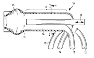
- FIG. 1 is a sectional view of a preferred embodiment of an air intake device according to the invention.
- FIG. 2 is a sectional view of the intake device taken along line I—I of FIG. 1;
- FIG. 3 is a sectional view taken along line I—I of FIG. 1 of a variant embodiment of an air intake device according to the invention with means for sealing the intake passages relative to one another;
- FIG. 4 is a sectional view of another embodiment of an intake device according to the invention.
- FIG. 1 an air intake device 10 is shown in section.
- This intake device 10 has a manifold 11 , intake tubes 12 and an adjusting unit 13 .
- Each intake tube 12 is connected to an intake channel or passage 14 which is formed by the manifold 11 in connection with the adjusting unit 13 .
- the manifold envelops a chamber 15 which merges directly with the intake channels 14 .
- the adjusting unit can be shifted lengthwise. If the adjusting unit 13 is partially retracted out of the manifold 11 the chamber 15 is enlarged and the intake passage length 16 is reduced. If the adjusting unit 13 is shifted inwardly the chamber 15 is reduced and the intake passage length 16 is increased.
- FIG. 2 the air intake device 10 is illustrated in a sectional view taken along line I—I of FIG. 1 .
- the air intake channels or passages 14 are arranged in a “clover leaf” with the adjusting unit 13 in a central area between them.
- the manifold 11 forms the outer wall and the adjusting unit 13 the inner wall of the air intake channels or passages 14 .
- the manifold 11 forms with adjusting element 13 a contact surface 17 which provides a sufficient sealing of the air intake channels or passages 14 relative to one another.
- FIG. 3 the air intake device is shown in a section taken along line I—I of FIG. 1, in a variant sealing of the intake passages 14 by means of gaskets 18 .
- These gaskets 18 are installed sealingly in the adjusting unit 13 and have a sealing edge 19 which is guided sealingly in the manifold 11 .
- FIG. 4 is a sectional illustration of an air intake device 10 according to the invention which comprises a manifold 11 with a chamber 15 , an adjusting unit 13 and air intake tubes 12 adjoining the air intake passages 14 .
- the adjusting unit is constructed of segments 20 which are connected by springs 21 .
- the spring stiffness of successive springs increases from the chamber 15 to the intake tubes 12 .
- the springs with the lower spring constant expand and open up the junctions 22 between the individual intake passages. Air passes through these junctions 22 and thus shortens the effective intake passage length 16 .
- the more the springs expand the more junctions 22 are opened and the more the intake passage length 16 is shortened.
- the springs 21 are inserted under tension between the segments 20 in order to bias the segments against each other. This assures that the segments 20 will join together sealingly in the unloaded state and will be brought sealingly together again after they are spread apart.
- the manifold 11 is designed such that the segments 20 are guided and no leakage from one intake channel 14 to the other can occur
Landscapes
- Engineering & Computer Science (AREA)
- Chemical & Material Sciences (AREA)
- Combustion & Propulsion (AREA)
- Mechanical Engineering (AREA)
- General Engineering & Computer Science (AREA)
- Manufacturing & Machinery (AREA)
- Physics & Mathematics (AREA)
- Geometry (AREA)
- Characterised By The Charging Evacuation (AREA)
Applications Claiming Priority (2)
| Application Number | Priority Date | Filing Date | Title |
|---|---|---|---|
| DE19948660 | 1999-10-08 | ||
| DE19948660A DE19948660A1 (de) | 1999-10-08 | 1999-10-08 | Ansaugvorrichtung |
Publications (1)
| Publication Number | Publication Date |
|---|---|
| US6371069B1 true US6371069B1 (en) | 2002-04-16 |
Family
ID=7925044
Family Applications (1)
| Application Number | Title | Priority Date | Filing Date |
|---|---|---|---|
| US09/684,956 Expired - Fee Related US6371069B1 (en) | 1999-10-08 | 2000-10-05 | Intake device |
Country Status (3)
| Country | Link |
|---|---|
| US (1) | US6371069B1 (de) |
| EP (1) | EP1091105A1 (de) |
| DE (1) | DE19948660A1 (de) |
Cited By (2)
| Publication number | Priority date | Publication date | Assignee | Title |
|---|---|---|---|---|
| US6539923B1 (en) * | 2001-09-14 | 2003-04-01 | Ducati Motor Holding S.P.A. | Apparatus for mixing air and fuel in an internal combustion engine |
| USD996328S1 (en) * | 2021-12-06 | 2023-08-22 | Kokusho Co., Ltd. | Exhaust gas purifier with function to improve fuel consumption |
Families Citing this family (3)
| Publication number | Priority date | Publication date | Assignee | Title |
|---|---|---|---|---|
| DE102004005135B4 (de) * | 2004-02-02 | 2006-02-02 | Siemens Ag | Ansaugkrümmer mit kontinuierlich variabler Kanal-Resonator-Kombination |
| DE102004062976A1 (de) * | 2004-12-22 | 2006-07-06 | Mahle Filtersysteme Gmbh | Lufteinlasseinrichtung einer Brennkraftmaschine |
| US11448171B1 (en) * | 2021-06-25 | 2022-09-20 | Ford Global Technologies, Llc | Hot-charge duct for turbocharger system |
Citations (4)
| Publication number | Priority date | Publication date | Assignee | Title |
|---|---|---|---|---|
| JPS60184924A (ja) * | 1984-03-02 | 1985-09-20 | Mazda Motor Corp | エンジンの吸気装置 |
| DE3608310A1 (de) | 1986-03-13 | 1987-09-17 | Bosch Gmbh Robert | Vorrichtung zur stufenlosen veraenderung der laenge des luftansaugrohres einer brennkraftmaschine |
| DE3843690A1 (de) * | 1988-12-23 | 1990-07-05 | Bayerische Motoren Werke Ag | Aus schwingrohrsystem und resonanzsystem kombinierte ansauganlage fuer mehrzylinder-brennkraftmaschinen |
| JPH02291422A (ja) * | 1989-05-02 | 1990-12-03 | Nissan Motor Co Ltd | 内燃機関の吸気装置 |
Family Cites Families (5)
| Publication number | Priority date | Publication date | Assignee | Title |
|---|---|---|---|---|
| GB670933A (en) * | 1952-05-29 | 1952-04-30 | Robert Guy Legros | Improvements in or relating to devices for increasing the maximum speed of vehicles or craft driven by internal combustion engines |
| JPS63198721A (ja) * | 1987-02-13 | 1988-08-17 | Fuji Heavy Ind Ltd | 内燃機関の可変吸気管長装置 |
| GB2210665B (en) * | 1987-10-07 | 1992-04-15 | Keith Gordon Hall | Engine intake system |
| JPH02502744A (ja) * | 1987-10-07 | 1990-08-30 | ホール、ケイス・ゴードン | エンジン吸気装置 |
| US4805573A (en) * | 1988-02-22 | 1989-02-21 | General Motors Corporation | Engine with variable area intake passages |
-
1999
- 1999-10-08 DE DE19948660A patent/DE19948660A1/de not_active Withdrawn
-
2000
- 2000-09-02 EP EP00119082A patent/EP1091105A1/de not_active Withdrawn
- 2000-10-05 US US09/684,956 patent/US6371069B1/en not_active Expired - Fee Related
Patent Citations (4)
| Publication number | Priority date | Publication date | Assignee | Title |
|---|---|---|---|---|
| JPS60184924A (ja) * | 1984-03-02 | 1985-09-20 | Mazda Motor Corp | エンジンの吸気装置 |
| DE3608310A1 (de) | 1986-03-13 | 1987-09-17 | Bosch Gmbh Robert | Vorrichtung zur stufenlosen veraenderung der laenge des luftansaugrohres einer brennkraftmaschine |
| DE3843690A1 (de) * | 1988-12-23 | 1990-07-05 | Bayerische Motoren Werke Ag | Aus schwingrohrsystem und resonanzsystem kombinierte ansauganlage fuer mehrzylinder-brennkraftmaschinen |
| JPH02291422A (ja) * | 1989-05-02 | 1990-12-03 | Nissan Motor Co Ltd | 内燃機関の吸気装置 |
Cited By (2)
| Publication number | Priority date | Publication date | Assignee | Title |
|---|---|---|---|---|
| US6539923B1 (en) * | 2001-09-14 | 2003-04-01 | Ducati Motor Holding S.P.A. | Apparatus for mixing air and fuel in an internal combustion engine |
| USD996328S1 (en) * | 2021-12-06 | 2023-08-22 | Kokusho Co., Ltd. | Exhaust gas purifier with function to improve fuel consumption |
Also Published As
| Publication number | Publication date |
|---|---|
| EP1091105A1 (de) | 2001-04-11 |
| DE19948660A1 (de) | 2001-04-12 |
Similar Documents
| Publication | Publication Date | Title |
|---|---|---|
| KR102667590B1 (ko) | 개방 위치를 정의하는 체크 밸브 삽입체와 이를 구비한 체크 밸브 | |
| US6732695B2 (en) | Intake manifold for an internal combustion engine | |
| US6752115B2 (en) | Air intake device for an internal combustion engine | |
| DE10341319B4 (de) | Schalldämpfer | |
| EP1195545B1 (de) | Faltenbalg mit spiralförmiger Struktur | |
| US9228542B2 (en) | Swirl vane air duct cuff assembly and method of manufacture | |
| CN101100966A (zh) | 用于卷绕管的柔性套管衬套 | |
| US6408810B1 (en) | Air intake device | |
| GB2301864A (en) | I.c.engine intake manifold assembly | |
| CN106345199A (zh) | 分离模块、线路模块以及通风装置 | |
| KR102306207B1 (ko) | 원동부 내의 원동 출구 및 복수의 하위 통로를 갖고 벤튜리 효과를 이용하는 진공 생성 장치 | |
| CN103982346A (zh) | 进气歧管 | |
| EP1206633B1 (de) | Ansaugeinrichtung für eine brennkraftmaschine | |
| US20030010321A1 (en) | Air intake device for an internal combustion engine with crankcase ventilation | |
| US6431136B2 (en) | Intake device with ram pipes and longitudinally adjustable resonance pipes | |
| KR20000070130A (ko) | 열가소성 합성수지의 흡입장치 | |
| KR930004048B1 (ko) | 열가소성 수지의 파이프 제조장치 | |
| US6460501B1 (en) | Air suction device for internal combustion engine | |
| ITTO20070529A1 (it) | Dispositivo silenziatore per un condotto atto ad essere percorso da un fluido e suo metodo di realizzazione. | |
| US6588389B1 (en) | Shift drum | |
| ITMO20130339A1 (it) | Condotto per la presa d'aria di un motore. | |
| KR950013478B1 (ko) | 합성사의 제조장치 | |
| JP4644245B2 (ja) | 内燃機関のための吸気設備 | |
| ITRM940146A1 (it) | Tubo di aspirazione per motori a combustione interna. | |
| US6247438B1 (en) | Intake pipe with shift drum |
Legal Events
| Date | Code | Title | Description |
|---|---|---|---|
| AS | Assignment |
Owner name: FILTERWERK MANN & HUMMEL GMBH, GERMANY Free format text: ASSIGNMENT OF ASSIGNORS INTEREST;ASSIGNOR:FISCHER, CHRISTIAN;REEL/FRAME:011507/0971 Effective date: 20001219 |
|
| FEPP | Fee payment procedure |
Free format text: PAYOR NUMBER ASSIGNED (ORIGINAL EVENT CODE: ASPN); ENTITY STATUS OF PATENT OWNER: LARGE ENTITY |
|
| FPAY | Fee payment |
Year of fee payment: 4 |
|
| REMI | Maintenance fee reminder mailed | ||
| LAPS | Lapse for failure to pay maintenance fees | ||
| STCH | Information on status: patent discontinuation |
Free format text: PATENT EXPIRED DUE TO NONPAYMENT OF MAINTENANCE FEES UNDER 37 CFR 1.362 |
|
| FP | Lapsed due to failure to pay maintenance fee |
Effective date: 20100416 |