US6342415B1 - Method and system for providing reduced-sized contacts in a semiconductor device - Google Patents
Method and system for providing reduced-sized contacts in a semiconductor device Download PDFInfo
- Publication number
- US6342415B1 US6342415B1 US09/404,395 US40439599A US6342415B1 US 6342415 B1 US6342415 B1 US 6342415B1 US 40439599 A US40439599 A US 40439599A US 6342415 B1 US6342415 B1 US 6342415B1
- Authority
- US
- United States
- Prior art keywords
- contact
- semiconductor device
- insulating layer
- gate stack
- gate
- Prior art date
- Legal status (The legal status is an assumption and is not a legal conclusion. Google has not performed a legal analysis and makes no representation as to the accuracy of the status listed.)
- Expired - Lifetime
Links
- 239000004065 semiconductor Substances 0.000 title claims abstract description 40
- 238000000034 method Methods 0.000 title abstract description 25
- 239000004020 conductor Substances 0.000 claims description 5
- 230000010363 phase shift Effects 0.000 claims description 3
- 239000006117 anti-reflective coating Substances 0.000 claims description 2
- 125000006850 spacer group Chemical group 0.000 description 9
- 230000006870 function Effects 0.000 description 5
- 238000010586 diagram Methods 0.000 description 2
- 238000005516 engineering process Methods 0.000 description 2
- 238000009413 insulation Methods 0.000 description 2
- 238000012986 modification Methods 0.000 description 2
- 230000004048 modification Effects 0.000 description 2
- 229920002120 photoresistant polymer Polymers 0.000 description 2
- 230000000740 bleeding effect Effects 0.000 description 1
- 238000005530 etching Methods 0.000 description 1
- 230000007257 malfunction Effects 0.000 description 1
- 239000000758 substrate Substances 0.000 description 1
Images


Classifications
-
- H—ELECTRICITY
- H01—ELECTRIC ELEMENTS
- H01L—SEMICONDUCTOR DEVICES NOT COVERED BY CLASS H10
- H01L21/00—Processes or apparatus adapted for the manufacture or treatment of semiconductor or solid state devices or of parts thereof
- H01L21/02—Manufacture or treatment of semiconductor devices or of parts thereof
- H01L21/04—Manufacture or treatment of semiconductor devices or of parts thereof the devices having at least one potential-jump barrier or surface barrier, e.g. PN junction, depletion layer or carrier concentration layer
- H01L21/18—Manufacture or treatment of semiconductor devices or of parts thereof the devices having at least one potential-jump barrier or surface barrier, e.g. PN junction, depletion layer or carrier concentration layer the devices having semiconductor bodies comprising elements of Group IV of the Periodic System or AIIIBV compounds with or without impurities, e.g. doping materials
- H01L21/30—Treatment of semiconductor bodies using processes or apparatus not provided for in groups H01L21/20 - H01L21/26
- H01L21/31—Treatment of semiconductor bodies using processes or apparatus not provided for in groups H01L21/20 - H01L21/26 to form insulating layers thereon, e.g. for masking or by using photolithographic techniques; After treatment of these layers; Selection of materials for these layers
- H01L21/3105—After-treatment
- H01L21/311—Etching the insulating layers by chemical or physical means
- H01L21/31144—Etching the insulating layers by chemical or physical means using masks
-
- H—ELECTRICITY
- H01—ELECTRIC ELEMENTS
- H01L—SEMICONDUCTOR DEVICES NOT COVERED BY CLASS H10
- H01L21/00—Processes or apparatus adapted for the manufacture or treatment of semiconductor or solid state devices or of parts thereof
- H01L21/70—Manufacture or treatment of devices consisting of a plurality of solid state components formed in or on a common substrate or of parts thereof; Manufacture of integrated circuit devices or of parts thereof
- H01L21/71—Manufacture of specific parts of devices defined in group H01L21/70
- H01L21/768—Applying interconnections to be used for carrying current between separate components within a device comprising conductors and dielectrics
- H01L21/76801—Applying interconnections to be used for carrying current between separate components within a device comprising conductors and dielectrics characterised by the formation and the after-treatment of the dielectrics, e.g. smoothing
- H01L21/76802—Applying interconnections to be used for carrying current between separate components within a device comprising conductors and dielectrics characterised by the formation and the after-treatment of the dielectrics, e.g. smoothing by forming openings in dielectrics
- H01L21/76816—Aspects relating to the layout of the pattern or to the size of vias or trenches
-
- H—ELECTRICITY
- H01—ELECTRIC ELEMENTS
- H01L—SEMICONDUCTOR DEVICES NOT COVERED BY CLASS H10
- H01L23/00—Details of semiconductor or other solid state devices
- H01L23/48—Arrangements for conducting electric current to or from the solid state body in operation, e.g. leads, terminal arrangements ; Selection of materials therefor
- H01L23/482—Arrangements for conducting electric current to or from the solid state body in operation, e.g. leads, terminal arrangements ; Selection of materials therefor consisting of lead-in layers inseparably applied to the semiconductor body
- H01L23/485—Arrangements for conducting electric current to or from the solid state body in operation, e.g. leads, terminal arrangements ; Selection of materials therefor consisting of lead-in layers inseparably applied to the semiconductor body consisting of layered constructions comprising conductive layers and insulating layers, e.g. planar contacts
-
- H—ELECTRICITY
- H01—ELECTRIC ELEMENTS
- H01L—SEMICONDUCTOR DEVICES NOT COVERED BY CLASS H10
- H01L2924/00—Indexing scheme for arrangements or methods for connecting or disconnecting semiconductor or solid-state bodies as covered by H01L24/00
- H01L2924/0001—Technical content checked by a classifier
- H01L2924/0002—Not covered by any one of groups H01L24/00, H01L24/00 and H01L2224/00
Definitions
- the present invention relates to semiconductor devices, more particularly to a method and system for reducing charge gain and charge loss due to contacts in semiconductor devices, such as a flash memory device.
- a conventional semiconductor device such as a memory, includes a large number of cells, which are typically floating gate devices such as floating gate transistors.
- FIG. 1 depicts a portion of a conventional semiconductor device 10 .
- the semiconductor device 10 includes cells 20 , 30 , and 40 formed on a substrate 11 .
- Each cell includes a gate stack 21 , 31 and 41 .
- Each gate stack 21 , 31 and 41 includes a floating gate 22 , 32 and 42 , respectively, and a control gate 24 , 34 and 44 , respectively.
- the cells 20 , 30 and 40 also include drains 29 and 39 and sources 19 and 49 . As depicted in FIG. 1, the cells 20 and 40 share a common drain 29 , while the cells 20 and 30 share a common source 19 .
- each cell 20 , 30 and 40 also includes spacers 26 and 28 , 36 and 38 , and 46 and 48 , respectively.
- a conventional electrical contact 52 is provided.
- the conventional contact 52 is provided within a conventional contact hole 50 .
- the conventional contact hole 50 is provided in an insulating layer 54 which otherwise covers the cells 20 , 30 and 40 .
- the insulating layer 54 insulates the cells 20 , 30 and 40 .
- the conventional contact hole 50 is filled with a conductive material to form the conventional contact 52 .
- the conventional semiconductor device 10 functions, one of ordinary skill in the art will readily realize that the conventional semiconductor device 10 is subject to unanticipated charge gain and charge loss because of the spacing of the contact 52 from a particular cell, such as the cell 20 .
- the current trend in semiconductor technology is toward higher densities.
- the components of the semiconductor device are more densely packed and made smaller.
- the cells 20 , 30 and 40 and the conventional contact 52 are relatively close.
- the thickness of the spacers 26 and 28 , 36 and 38 and 46 and 48 is between approximately one thousand and two thousand Angstroms.
- the conventional contact 52 is approximately 0.28 to 0.4 ⁇ m wide.
- conventional contacts 52 which are less than 0.28-0.3 ⁇ m wide.
- the widths of the conventional contacts 52 are centered around 0.28 ⁇ m. This distance is approximately the smallest that an aperture in a photoresist mask (not shown) can be made using conventional photolithographic techniques.
- the photoresist mask is used in forming the conventional contact hole 50 by etching the underlying areas of the insulating layer 54 .
- the conventional contact 52 is also closely spaced to neighboring cells 20 , 30 and 40 .
- the distance between the base of the conventional contact 52 and the edge of a nearest gate in a gate stack, such as the gate stack 21 is very small. In some cases, the distance between the gate stack and the contact may be between 0.15 and 0.3 ⁇ m.
- the small spacing between the conventional contact 52 and the gate stack of particular cell, such as the cell 20 causes unanticipated charge gain and charge loss from the cell 20 .
- the conventional contact 52 is typically separated from the edge of the gate stack 21 by such a small distance, the portion of the insulating layer 54 between the conventional contact 52 and the gate stack 21 is very thin.
- the combination of the spacer 26 and the insulating layer 54 may not provide sufficient insulation to prevent the gate stack 21 from being electrically coupled to the conventional contact 52 through the spacer 26 and insulating layer 54 .
- charge on the conventional contact 52 may travel to the gate stack 21 when a user does not desire the floating gate 22 to store charge.
- a charge stored on the floating gate 22 may travel to the conventional contact 52 .
- a charge intentionally stored on the floating gate 22 may bleed away. Consequently, the cell 20 is subject to unanticipated charge gain and charge loss. As a result, the cell 20 may not function as desired.
- the present invention provides a method and system for providing a contact in a semiconductor device including a plurality of gates.
- the method and system comprise providing an insulating layer substantially surrounding at least a portion of the plurality of gates and providing at least one contact within the insulating layer.
- the at least one contact has a reduced width of less than approximately 0.28 ⁇ m.
- the present invention provides a greater spacing between the contact and the closest gate stack without increasing the spacing between gate stacks or between the center of the contact and the gate stack. Consequently, a higher density of devices can be achieved while reducing the charge gain and charge loss through the contact.
- FIG. 1 is a diagram of a conventional semiconductor device
- FIG. 2 is a diagram of a semiconductor device including a contact in accordance with the present invention.
- FIG. 3A is a flow chart depicting one embodiment of a method for providing a semiconductor device in accordance with the present invention.
- FIG. 3B is a flow chart depicting one embodiment of a method for providing the contact in accordance with the present invention.
- FIG. 3C is a flow chart depicting one embodiment of a method for providing the contact hole in accordance with the present invention.
- the present invention relates to an improvement in semiconductor processing.
- the following description is presented to enable one of ordinary skill in the art to make and use the invention and is provided in the context of a patent application and its requirements.
- Various modifications to the preferred embodiment will be readily apparent to those skilled in the art and the generic principles herein may be applied to other embodiments.
- the present invention is not intended to be limited to the embodiment shown, but is to be accorded the widest scope consistent with the principles and features described herein.
- a conventional semiconductor device such as a flash memory, includes a large number of cells, which are typically floating gate devices such as floating gate transistors.
- the cells also include sources and drains.
- each cell also includes spacers.
- a conventional contact hole is filled with a conductive material to provide a conventional contact.
- the conventional contact hole is provided in a conventional insulating layer that may otherwise cover and insulate the cells.
- the conventional semiconductor device functions, one of ordinary skill in the art will readily realize that the conventional semiconductor device is subject to unanticipated charge gain and charge loss because of the spacing of the contact and a nearest cell.
- the cells and conventional contacts of a conventional semiconductor device are relatively close.
- the width of the conventional contacts is limited by conventional photolithographic techniques to between about 0.28 ⁇ m and 0.4 ⁇ m.
- conventional contacts having widths of less than 0.28-0.3 ⁇ m are difficult to produce.
- the distance between the base of the conventional contact and the edge of nearest gates of a gate stack is very small. The small spacing between the conventional contact and the gate stack causes undesirable charge gain and charge loss from the cell.
- the conventional contact is typically separated from the edge of the nearest gate stack by such a small distance, the portion of the insulating layer and any spacer between the conventional contact may allow charge stored on the cell to travel to the contact, thereby bleeding away. For similar reasons, a charge on the contact may travel to the nearest cell. Consequently, the cell is subject to unanticipated charge gain and charge loss. As a result, the semiconductor device may malfunction, which is undesirable.
- the present invention provides a method and system for providing a contact in a semiconductor device including a plurality of gates.
- the method and system comprise providing an insulating layer substantially surrounding at least a portion of the plurality of gates and providing at least one contact within the insulating layer.
- the at least one contact has a reduced width that is less than approximately 0.28 ⁇ m.
- the present invention will be described in terms of a particular device having certain components and particular techniques for performing certain steps. However, one of ordinary skill in the art will readily recognize that this method and system will operate effectively for other devices having other components and other techniques. Furthermore, the present invention will be described in terms of a particular semiconductor memory device. However, nothing prevents the method and system from being utilized with another semiconductor device.
- FIG. 2 depicting one embodiment of a semiconductor device 100 , such as a memory, including a contact in accordance with the present invention.
- the semiconductor device 100 includes a number of cells 120 , 130 and 140 , which are typically floating gate devices such as floating gate transistors.
- Each cell 120 , 130 and 140 includes a gate stack 121 , 131 and 141 .
- Each gate stack 121 , 131 and 141 includes a floating gate 122 , 132 and 142 , respectively, and a control gate 124 , 134 and 144 , respectively.
- the cells 120 , 130 and 140 also include drains 129 and 139 and sources 19 and 149 .
- each cell 120 , 130 and 140 also includes spacers 126 and 128 , 136 and 138 , and 146 and 148 , respectively.
- the spacers 126 , 128 , 136 , 138 , 146 and 148 are approximately one thousand to two thousand Angstroms thick.
- an electrical contact 152 in accordance with the present invention is used.
- the electrical contact 152 is provided within a contact hole 150 in accordance with the present invention.
- the contact hole 150 is provided in an insulating layer 154 which otherwise covers the cells 120 , 130 and 140 .
- the insulating layer 154 insulates the cells 120 , 130 and 140 .
- the contact hole 150 is filled with a conductive material to form the contact 152 .
- the contact hole 150 and, therefore, the contact 152 have a reduced with that is less than approximately 0.28 ⁇ m.
- the width of the contact hole 150 and the contact 152 is greater than approximately 0.2 ⁇ m and less than approximately 0.25 ⁇ m. It is currently believed that such a width will provide a greater distance to the nearest gate stack 121 while maintaining a contact resistance that is sufficiently low to allow the contact 152 to function.
- the distance between the base of the contact hole and the nearest gate stack, such as the gate stack 121 has increased by 0.05-0.1 ⁇ m.
- the edge of the contact 152 is separated from the edge of the nearest gate stack 121 by a greater distance than in the conventional semiconductor device 10 depicted in FIG. 1 .
- the edge of the contact 150 is a greater distance from the edge of the gate stack 121 , there is more of the insulating layer 154 between the contact 152 and the edge of the gate stack 121 .
- the insulating layer 154 is better able to electrically insulate the contact 152 from the edge of the gate stack 121 .
- charge intentionally stored by the memory cell 120 is much less likely to travel through the insulating layer 154 to the contact 152 .
- charge on the contact 152 is much less likely to travel through the insulating layer to the gate stack 121 .
- unwanted charge gain and charge loss may be reduced or eliminated in a semiconductor device which has components relatively densely packed.
- FIG. 3A depicts one embodiment of a method 200 for providing a semiconductor device in accordance with the present invention.
- the memory cells 120 , 130 and 140 are provided, via step 202 .
- step 202 includes at least providing the gate stacks 121 , 131 , and 141 .
- Step 202 may also include providing the spacers 126 , 128 , 136 , 138 , 146 , and 148 .
- the insulating layer 154 is then provided on the cells 120 , 130 and 140 , via step 204 .
- One or more contacts 152 having a reduced width of less than 0.28 ⁇ m, such as the contact 152 are then provided, via step 206 .
- the width of the contact hole 150 and the contact 152 is greater than approximately 0.2 ⁇ m and less than approximately 0.25 ⁇ m. It is currently believed that such a width will provide a greater distance to the nearest gate stack 121 while maintaining a contact resistance that is sufficiently low to allow the contact 152 to function. Also in a preferred embodiment, the edges of the contacts 152 provided in step 206 will be separated from the closest edge of the nearest gate stack by 0.05-0.1 ⁇ m more than in the conventional semiconductor device 10 shown in FIG. 1 . Referring back to FIG.
- FIG. 3B depicts one embodiment of a method 210 for performing the step 206 of providing contacts 152 having reduced widths.
- One or more contact holes 150 having reduced widths are provided in the insulating layer 154 , via step 212 .
- the contact hole 150 is filled with a conductive material to form a contact 152 having a reduced width, via step 214 .
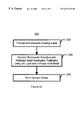
- FIG. 3C depicts one embodiment of a method 220 for performing the step 210 of providing the contact hole(s) having a reduced width.
- An antireflective coating is provided on the insulating layer 154 , via step 222 .
- a resist structure having apertures above the desired positions of the contact holes is provided, via step 224 .
- the resist structure is provided using ultraviolet light using a phase shift mask. In one embodiment, light having a wavelength of approximately 248 nm is used in conjunction with a phase shift mask.
- the apertures in the resist structure are approximately the same size as the desired size of the contact hole 150 .
- the etch for the contact hole 150 is then performed, via step 226 .
- the contacts are etched using a C4F 8 /O 2 /Ar etch chemistry.
- the method 220 ensures that the contact hole 150 and, therefore, the contact 152 will have a reduced width.
- the width of the contact hole 150 and the contact 152 is between approximately 0.2 ⁇ m and 0.28 ⁇ m.
Abstract
Description
Claims (6)
Priority Applications (1)
| Application Number | Priority Date | Filing Date | Title |
|---|---|---|---|
| US09/404,395 US6342415B1 (en) | 1999-09-23 | 1999-09-23 | Method and system for providing reduced-sized contacts in a semiconductor device |
Applications Claiming Priority (1)
| Application Number | Priority Date | Filing Date | Title |
|---|---|---|---|
| US09/404,395 US6342415B1 (en) | 1999-09-23 | 1999-09-23 | Method and system for providing reduced-sized contacts in a semiconductor device |
Publications (1)
| Publication Number | Publication Date |
|---|---|
| US6342415B1 true US6342415B1 (en) | 2002-01-29 |
Family
ID=23599428
Family Applications (1)
| Application Number | Title | Priority Date | Filing Date |
|---|---|---|---|
| US09/404,395 Expired - Lifetime US6342415B1 (en) | 1999-09-23 | 1999-09-23 | Method and system for providing reduced-sized contacts in a semiconductor device |
Country Status (1)
| Country | Link |
|---|---|
| US (1) | US6342415B1 (en) |
Citations (14)
| Publication number | Priority date | Publication date | Assignee | Title |
|---|---|---|---|---|
| US4758305A (en) * | 1986-03-11 | 1988-07-19 | Texas Instruments Incorporated | Contact etch method |
| US5521111A (en) * | 1993-05-10 | 1996-05-28 | Nec Corporation | Process of fabricating memory cell with a switching transistor and a trench-stacked capacitor coupled in series |
| US5716883A (en) * | 1996-11-06 | 1998-02-10 | Vanguard International Semiconductor Corporation | Method of making increased surface area, storage node electrode, with narrow spaces between polysilicon columns |
| US5718800A (en) * | 1995-11-08 | 1998-02-17 | Micron Technology, Inc. | Self-aligned N+/P+ doped polysilicon plugged contacts to N+/P+ doped polysilicon gates and to N+/P+ doped source/drain regions |
| US5726803A (en) * | 1994-09-30 | 1998-03-10 | Nippon Carbide Kogyo Kabushiki Kaisha | Lens-type retroreflective sheeting |
| US5731242A (en) * | 1993-10-15 | 1998-03-24 | Intel Corporation | Self-aligned contact process in semiconductor fabrication |
| US5914504A (en) * | 1995-06-16 | 1999-06-22 | Imec Vzw | DRAM applications using vertical MISFET devices |
| US5920088A (en) * | 1995-06-16 | 1999-07-06 | Interuniversitair Micro-Electronica Centrum (Imec Vzw) | Vertical MISFET devices |
| US5926709A (en) * | 1995-03-30 | 1999-07-20 | Nec Corporation | Process of fabricating miniature memory cell having storage capacitor with wide surface area |
| US5928967A (en) * | 1996-06-10 | 1999-07-27 | International Business Machines Corporation | Selective oxide-to-nitride etch process using C4 F8 /CO/Ar |
| US5963800A (en) * | 1995-06-16 | 1999-10-05 | Interuniversitair Micro-Elektronica Centrum (Imec Vzw) | CMOS integration process having vertical channel |
| US5969381A (en) * | 1997-02-26 | 1999-10-19 | Nec Corporation | Semiconductor device with unbreakable testing elements for evaluating components and process of fabrication thereof |
| US6030860A (en) * | 1997-12-19 | 2000-02-29 | Advanced Micro Devices, Inc. | Elevated substrate formation and local interconnect integrated fabrication |
| US6121156A (en) * | 1998-04-28 | 2000-09-19 | Cypress Semiconductor Corporation | Contact monitor, method of forming same and method of analyzing contact-, via-and/or trench-forming processes in an integrated circuit |
-
1999
- 1999-09-23 US US09/404,395 patent/US6342415B1/en not_active Expired - Lifetime
Patent Citations (14)
| Publication number | Priority date | Publication date | Assignee | Title |
|---|---|---|---|---|
| US4758305A (en) * | 1986-03-11 | 1988-07-19 | Texas Instruments Incorporated | Contact etch method |
| US5521111A (en) * | 1993-05-10 | 1996-05-28 | Nec Corporation | Process of fabricating memory cell with a switching transistor and a trench-stacked capacitor coupled in series |
| US5731242A (en) * | 1993-10-15 | 1998-03-24 | Intel Corporation | Self-aligned contact process in semiconductor fabrication |
| US5726803A (en) * | 1994-09-30 | 1998-03-10 | Nippon Carbide Kogyo Kabushiki Kaisha | Lens-type retroreflective sheeting |
| US5926709A (en) * | 1995-03-30 | 1999-07-20 | Nec Corporation | Process of fabricating miniature memory cell having storage capacitor with wide surface area |
| US5963800A (en) * | 1995-06-16 | 1999-10-05 | Interuniversitair Micro-Elektronica Centrum (Imec Vzw) | CMOS integration process having vertical channel |
| US5914504A (en) * | 1995-06-16 | 1999-06-22 | Imec Vzw | DRAM applications using vertical MISFET devices |
| US5920088A (en) * | 1995-06-16 | 1999-07-06 | Interuniversitair Micro-Electronica Centrum (Imec Vzw) | Vertical MISFET devices |
| US5718800A (en) * | 1995-11-08 | 1998-02-17 | Micron Technology, Inc. | Self-aligned N+/P+ doped polysilicon plugged contacts to N+/P+ doped polysilicon gates and to N+/P+ doped source/drain regions |
| US5928967A (en) * | 1996-06-10 | 1999-07-27 | International Business Machines Corporation | Selective oxide-to-nitride etch process using C4 F8 /CO/Ar |
| US5716883A (en) * | 1996-11-06 | 1998-02-10 | Vanguard International Semiconductor Corporation | Method of making increased surface area, storage node electrode, with narrow spaces between polysilicon columns |
| US5969381A (en) * | 1997-02-26 | 1999-10-19 | Nec Corporation | Semiconductor device with unbreakable testing elements for evaluating components and process of fabrication thereof |
| US6030860A (en) * | 1997-12-19 | 2000-02-29 | Advanced Micro Devices, Inc. | Elevated substrate formation and local interconnect integrated fabrication |
| US6121156A (en) * | 1998-04-28 | 2000-09-19 | Cypress Semiconductor Corporation | Contact monitor, method of forming same and method of analyzing contact-, via-and/or trench-forming processes in an integrated circuit |
Similar Documents
| Publication | Publication Date | Title |
|---|---|---|
| JP2000299448A (en) | Manufacture of dram cell capacitor | |
| US6828219B2 (en) | Stacked spacer structure and process | |
| TWI571974B (en) | Semiconductor transistor and flash memory, and manufacturing method thereof | |
| JP2004088100A (en) | Structure of built-in dram with vertical device array and bordered bit line contact, and manufacturing method of dram | |
| US20050275043A1 (en) | Novel semiconductor device design | |
| US7071059B1 (en) | Method for forming recess gate of semiconductor device | |
| US6451652B1 (en) | Method for forming an EEPROM cell together with transistor for peripheral circuits | |
| US6787843B2 (en) | Nonvolatile semiconductor memory cell and associated semiconductor circuit configuration and method for the fabrication of the circuit configuration | |
| KR100334572B1 (en) | Method of forming a self aligned contact in a semiconductor device | |
| US6448130B1 (en) | Method of selectively forming silicide film of merged DRAM and Logic | |
| US6342415B1 (en) | Method and system for providing reduced-sized contacts in a semiconductor device | |
| US6369416B1 (en) | Semiconductor device with contacts having a sloped profile | |
| CN102789985B (en) | Semiconductor apparatus and manufacturing method thereof | |
| US20040206722A1 (en) | Method for the formation of contact holes for a number of contact regions for components integrated in a substrate | |
| KR20060088637A (en) | Flash memory device having peripheral transistor and method the same | |
| KR100543637B1 (en) | Manufacturing Method of Flash Memory Device | |
| JP2003158206A (en) | Method for manufacturing silicide film of flat cell memory device | |
| US20010045648A1 (en) | Method and system for decreasing the spaces between wordlines | |
| US6974995B1 (en) | Method and system for forming dual gate structures in a nonvolatile memory using a protective layer | |
| KR20020042309A (en) | Method for manufacturing semiconductor semiconductor memory device | |
| JP3165693B2 (en) | Stacked capacitor type DRAM | |
| KR100268863B1 (en) | Method for fabricating semiconductor device | |
| KR100558540B1 (en) | Method for fabricating semiconduntor device | |
| KR20030000219A (en) | Method for forming the line of semiconductor device | |
| KR100519163B1 (en) | Manufacturing Method of Flash Memory Device_ |
Legal Events
| Date | Code | Title | Description |
|---|---|---|---|
| AS | Assignment |
Owner name: ADVANCED MICRO DEVICES, INC., CALIFORNIA Free format text: ASSIGNMENT OF ASSIGNORS INTEREST;ASSIGNORS:HUI, ANGELA T.;PHAM, TUAN DUC;RAMSBEY, MARK T.;AND OTHERS;REEL/FRAME:010269/0970;SIGNING DATES FROM 19990909 TO 19990915 |
|
| FPAY | Fee payment |
Year of fee payment: 4 |
|
| AS | Assignment |
Owner name: SPANSION INC., CALIFORNIA Free format text: ASSIGNMENT OF ASSIGNORS INTEREST;ASSIGNOR:ADVANCED MICRO DEVICES, INC.;REEL/FRAME:019028/0662 Effective date: 20070131 |
|
| AS | Assignment |
Owner name: SPANSION LLC, CALIFORNIA Free format text: ASSIGNMENT OF ASSIGNORS INTEREST;ASSIGNOR:SPANSION INC.;REEL/FRAME:019069/0113 Effective date: 20070131 |
|
| FPAY | Fee payment |
Year of fee payment: 8 |
|
| AS | Assignment |
Owner name: BARCLAYS BANK PLC, NEW YORK Free format text: SECURITY AGREEMENT;ASSIGNORS:SPANSION LLC;SPANSION INC.;SPANSION TECHNOLOGY INC.;AND OTHERS;REEL/FRAME:024522/0338 Effective date: 20100510 |
|
| REMI | Maintenance fee reminder mailed | ||
| FEPP | Fee payment procedure |
Free format text: PETITION RELATED TO MAINTENANCE FEES GRANTED (ORIGINAL EVENT CODE: PMFG); ENTITY STATUS OF PATENT OWNER: LARGE ENTITY Free format text: PETITION RELATED TO MAINTENANCE FEES FILED (ORIGINAL EVENT CODE: PMFP); ENTITY STATUS OF PATENT OWNER: LARGE ENTITY |
|
| LAPS | Lapse for failure to pay maintenance fees | ||
| REIN | Reinstatement after maintenance fee payment confirmed | ||
| FP | Lapsed due to failure to pay maintenance fee |
Effective date: 20140129 |
|
| PRDP | Patent reinstated due to the acceptance of a late maintenance fee |
Effective date: 20140514 |
|
| FPAY | Fee payment |
Year of fee payment: 12 |
|
| STCF | Information on status: patent grant |
Free format text: PATENTED CASE |
|
| SULP | Surcharge for late payment | ||
| AS | Assignment |
Owner name: SPANSION INC., CALIFORNIA Free format text: RELEASE BY SECURED PARTY;ASSIGNOR:BARCLAYS BANK PLC;REEL/FRAME:035201/0159 Effective date: 20150312 Owner name: SPANSION TECHNOLOGY LLC, CALIFORNIA Free format text: RELEASE BY SECURED PARTY;ASSIGNOR:BARCLAYS BANK PLC;REEL/FRAME:035201/0159 Effective date: 20150312 Owner name: SPANSION LLC, CALIFORNIA Free format text: RELEASE BY SECURED PARTY;ASSIGNOR:BARCLAYS BANK PLC;REEL/FRAME:035201/0159 Effective date: 20150312 |
|
| AS | Assignment |
Owner name: MORGAN STANLEY SENIOR FUNDING, INC., NEW YORK Free format text: SECURITY INTEREST;ASSIGNORS:CYPRESS SEMICONDUCTOR CORPORATION;SPANSION LLC;REEL/FRAME:035240/0429 Effective date: 20150312 |