US6325235B1 - Receptacle structure and a method of packaging a product and more particularly a beverage such as beer by means of the receptacle - Google Patents
Receptacle structure and a method of packaging a product and more particularly a beverage such as beer by means of the receptacle Download PDFInfo
- Publication number
- US6325235B1 US6325235B1 US09/485,181 US48518100A US6325235B1 US 6325235 B1 US6325235 B1 US 6325235B1 US 48518100 A US48518100 A US 48518100A US 6325235 B1 US6325235 B1 US 6325235B1
- Authority
- US
- United States
- Prior art keywords
- receptacle
- wall
- hollow body
- filling
- receptacle according
- Prior art date
- Legal status (The legal status is an assumption and is not a legal conclusion. Google has not performed a legal analysis and makes no representation as to the accuracy of the status listed.)
- Expired - Fee Related
Links
Images


Classifications
-
- B—PERFORMING OPERATIONS; TRANSPORTING
- B65—CONVEYING; PACKING; STORING; HANDLING THIN OR FILAMENTARY MATERIAL
- B65D—CONTAINERS FOR STORAGE OR TRANSPORT OF ARTICLES OR MATERIALS, e.g. BAGS, BARRELS, BOTTLES, BOXES, CANS, CARTONS, CRATES, DRUMS, JARS, TANKS, HOPPERS, FORWARDING CONTAINERS; ACCESSORIES, CLOSURES, OR FITTINGS THEREFOR; PACKAGING ELEMENTS; PACKAGES
- B65D85/00—Containers, packaging elements or packages, specially adapted for particular articles or materials
- B65D85/70—Containers, packaging elements or packages, specially adapted for particular articles or materials for materials not otherwise provided for
- B65D85/72—Containers, packaging elements or packages, specially adapted for particular articles or materials for materials not otherwise provided for for edible or potable liquids, semiliquids, or plastic or pasty materials
- B65D85/73—Containers, packaging elements or packages, specially adapted for particular articles or materials for materials not otherwise provided for for edible or potable liquids, semiliquids, or plastic or pasty materials with means specially adapted for effervescing the liquids, e.g. for forming bubbles or beer head
-
- B—PERFORMING OPERATIONS; TRANSPORTING
- B65—CONVEYING; PACKING; STORING; HANDLING THIN OR FILAMENTARY MATERIAL
- B65D—CONTAINERS FOR STORAGE OR TRANSPORT OF ARTICLES OR MATERIALS, e.g. BAGS, BARRELS, BOTTLES, BOXES, CANS, CARTONS, CRATES, DRUMS, JARS, TANKS, HOPPERS, FORWARDING CONTAINERS; ACCESSORIES, CLOSURES, OR FITTINGS THEREFOR; PACKAGING ELEMENTS; PACKAGES
- B65D1/00—Rigid or semi-rigid containers having bodies formed in one piece, e.g. by casting metallic material, by moulding plastics, by blowing vitreous material, by throwing ceramic material, by moulding pulped fibrous material or by deep-drawing operations performed on sheet material
- B65D1/02—Bottles or similar containers with necks or like restricted apertures, designed for pouring contents
- B65D1/0223—Bottles or similar containers with necks or like restricted apertures, designed for pouring contents characterised by shape
- B65D1/023—Neck construction
- B65D1/0238—Integral frangible closures
-
- B—PERFORMING OPERATIONS; TRANSPORTING
- B65—CONVEYING; PACKING; STORING; HANDLING THIN OR FILAMENTARY MATERIAL
- B65D—CONTAINERS FOR STORAGE OR TRANSPORT OF ARTICLES OR MATERIALS, e.g. BAGS, BARRELS, BOTTLES, BOXES, CANS, CARTONS, CRATES, DRUMS, JARS, TANKS, HOPPERS, FORWARDING CONTAINERS; ACCESSORIES, CLOSURES, OR FITTINGS THEREFOR; PACKAGING ELEMENTS; PACKAGES
- B65D1/00—Rigid or semi-rigid containers having bodies formed in one piece, e.g. by casting metallic material, by moulding plastics, by blowing vitreous material, by throwing ceramic material, by moulding pulped fibrous material or by deep-drawing operations performed on sheet material
- B65D1/02—Bottles or similar containers with necks or like restricted apertures, designed for pouring contents
- B65D1/06—Bottles or similar containers with necks or like restricted apertures, designed for pouring contents with closable apertures at bottom
-
- B—PERFORMING OPERATIONS; TRANSPORTING
- B65—CONVEYING; PACKING; STORING; HANDLING THIN OR FILAMENTARY MATERIAL
- B65D—CONTAINERS FOR STORAGE OR TRANSPORT OF ARTICLES OR MATERIALS, e.g. BAGS, BARRELS, BOTTLES, BOXES, CANS, CARTONS, CRATES, DRUMS, JARS, TANKS, HOPPERS, FORWARDING CONTAINERS; ACCESSORIES, CLOSURES, OR FITTINGS THEREFOR; PACKAGING ELEMENTS; PACKAGES
- B65D51/00—Closures not otherwise provided for
- B65D51/24—Closures not otherwise provided for combined or co-operating with auxiliary devices for non-closing purposes
- B65D51/249—Closures not otherwise provided for combined or co-operating with auxiliary devices for non-closing purposes the closure being specifically formed for supporting the container
Definitions
- the present invention relates to a closed receptacle that is used more particularly, but not exclusively, for packaging foodstuffs, and in particular liquid beverages, and in which there is provided a chamber for containing a gas under pressure, e.g. nitrogen, which gas is automatically released when the receptacle is opened and acts on the contents of the receptacle.
- the invention also relates to a novel method of packaging a product by means of the receptacle.
- the invention is particularly, but not exclusively, applicable to making a closed receptacle containing beer and advantageously capable of being in the form of a glass, e.g.
- thermoplastic resins obtained by injection blow-molding one or more thermoplastic resins, with the action of the gas on the beer when the glass is opened enabling a head to be formed that is firm and smooth.
- This novel packaging in the form of a glass advantageously gives consumers at home the chance to drink beer comparable to beer that has been served traditionally, from a hand-pulled pump, for example in premises specialized in selling drinks.
- such a can is in the form of a closed hollow body made up of two distinct portions: a main portion which is generally cylindrical and closed at its bottom end by a bottom wall, and having a top face that is open; together with a cover or closure member designed to be fitted to and fixed on the main portion so as to close it.
- the main portion and the cover or closure member are manufactured separately.
- manual opening means are provided on the cover or closure member, which means are generally in the form of a tab enabling the consumer to open the can by hand so as to be able to empty out its contents, with this being done by pushing or pulling the outside face of the cover or closure member on the can so as to rupture it by piercing it and/or by tearing it.
- the first step consists in filling the main portion of the receptacle with the product, prior to putting the cover or closure member into place. Once the main portion has been filled, the cover or closure member is fixed to the main portion by any appropriate means, and the full receptacle is suitable for being put on sale.
- the step of fixing the cover or closure member on the main portion is relatively difficult to perform because of the sealing constraints that must be satisfied between the cover and the main portion of the receptacle, which constraints are made all the more difficult to satisfy when sealing needs to be achieved over a relatively long length, e.g. the entire periphery of the main portion of the receptacle.
- receptacles containing a chamber filled with gas under pressure which gas is released when the receptacle is opened and acts on the product contained in the receptacle.
- This type of receptacle is used in particular in the field of packaging beer in cans.
- numerous brewers fit their cans of beer with internal chambers that are in communication with the inside of the can and that contain a gas under pressure, e.g. nitrogen.
- the chamber is in the form of a small hollow add-on part [sometimes called a “widget”] which can have a wide variety of shapes, which is usually made of plastic, and which is fixed by any appropriate means to the inside face of the bottom wall of the can.
- the add-on part also has one or more escape openings formed therein, enabling the inside of the hollow part to communicate with the inside of the can.
- beer is packaged in a can having a chamber containing a gas under pressure as follows.
- the add-on part that is to form the chamber containing the gas under pressure is fixed to the inside of the main portion of the can, by being inserted through its open top face.
- This part is fixed by any appropriate known means, and in particular by adhesive or by heat-sealing.
- This step is relatively difficult, and it also requires special tooling to be used that is capable of passing through the opening in the top face of the main portion of the can so as to enable the chamber to be positioned and fixed in the bottom of the can.
- the main portion of the can is filled with beer, and a predetermined quantity of gas under pressure is inserted, where the quantity is a function of the capacity of the can.
- the gas used is nitrogen.
- a last step consists in turning the can upside-down so as to cause its bottom to be on top, thereby having the effect of filling the chamber with the gas under pressure, with molecules of gas rising towards the chamber and entering therein. After a given length of time has elapsed, the chamber is full of gas under pressure and the can be handled freely, in particular for the purpose of being transported to its point of sale.
- a can constituted by a tubular body closed at both sides by two separate closure walls that are sealed thereto: one closure wall (top wall) is openable via a pull ring.
- An add-on hollow part (widget) constituted by an inner partition wall with a small communication orifice is mounted inside the tubular body. This inner partition wall is locked to the rim of the tubular element by the closure of the bottom closure wall, or may be sealed to the tubular body prior to the closure of the bottom closure wall.
- a can having a tubular body and a separate bottom closure is advantageous since it enables to introduce the beverage and the gas in the can via the bottom opening of the tubular wall, prior to the fitting of the partition wall to the rim of the tubular body.
- this solution complicates the assembling operation of the can and in particular the step of fixing the bottom closing wall to the tubular body is relatively difficult to perform because of the sealing constraints that must be satisfied over the entire periphery of the tubular body. This step is further more difficult to perform when the bottom closure wall is used for locking the inner partition wall to the rim of the tubular body.
- the main object of the invention is to propose a receptacle that makes it possible to simplify the process of packaging a product in a receptacle of the type including an internal chamber for the purpose of containing a gas under pressure that is suitable for being released when the receptacle is opened.
- the invention also provides a method of packaging a product by means of a receptacle according to claim 1 .
- the product is inserted into the inside of the hollow body by causing it to pass through the filling orifice, a quantity of gas is inserted through the same orifice, the hollow part is put into place through said orifice, and the hollow body is closed by closing the filling orifice.
- the novel structure of the receptacle in accordance with claim 1 makes it possible to simplify the operations of installing and fixing the add-on chamber-forming part relative to the hollow body. It also makes it possible to perform packaging from a first step of filling the receptacle while keeping the receptacle in the same position, i.e. with its filling wall on top, thereby avoiding an operation of turning the receptacle upside-down in order to fill the hollow part with the gas under pressure.
- the filling orifice must be dimensioned so as to allow the hollow part to pass therethrough, but in practice the hollow part is compact. Consequently, the filling orifice is advantageously of a diameter that is small compared with the diameter of the hollow body of the receptacle, thereby making it easier to comply with sealing constraints at the filling orifice.
- FIG. 1 is a section view through a first embodiment of a glass-shaped receptacle of the invention whose bottom forms a punt serving as a housing for the filling neck of the receptacle;
- FIGS. 2 and 3 are section views through a mold showing the steps of blowing a parison to obtain the receptacle of FIG. 1;
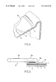
- FIG. 4 is a fragmentary perspective view of the emptying wall of the FIG. 1 receptacle in which a circular groove is provided defining a zone of weakness enabling the emptying wall to be ruptured manually;
- FIG. 5 is a diagram showing an opening tab fixed onto the emptying wall of the FIG. 1 receptacle and enabling said emptying wall to be ruptured by hand;
- FIGS. 6 and 7 show two main stages in the use of the tab of FIG. 5 to open the receptacle of FIG. 1;
- FIG. 8 shows the main steps implemented for packaging a liquid in the receptacle of FIG. 1;
- FIG. 9 shows a variant embodiment of the closure cap of the FIG. 1 receptacle in which the cap includes a hollow part filled with gas under pressure;
- FIG. 10 shows another variant embodiment of a glass of the invention in which the closure cap forms a stable foot for the glass.
- FIG. 1 shows a first embodiment of a receptacle of the invention, which is more particularly intended to contain a beverage, for example beer.
- the receptacle 1 comprises a hollow body 2 constituted by a one-piece molding, comprising a side wall 2 a, and two end walls 2 b and 2 c.
- the end wall 2 b corresponds to the emptying wall of the body 2 and it is designed to be ruptured manually in a manner described in greater detail below with reference to FIGS. 4 to 7 .
- the end wall 2 c corresponds to the filling wall of the hollow body 2 and it includes an orifice 3 through which the hollow body is filled, and suitable for being closed by closure means 4 .
- the hollow body is more particularly in the form of a glass of section that flares from its filling wall 2 c to its emptying wall 2 b.
- the filling wall 2 c is in the form of a reentrant kick or “punt” projecting into the hollow body and defining a cavity 5 , with a neck 6 being formed at the filling orifice 3 and being fully received inside the cavity 5 .
- the closure means 4 are in the form of a cap 7 suitable for being removably fitted to the neck 6 .
- the neck 6 is threaded and the cap 7 has an inside thread enabling the cap 7 to be screwed onto the neck 6 until the cap 7 bears against a collar 6 a on the neck 6 , thereby ensuring sealed closure.
- the cap 7 can thus easily be installed on the neck 6 in order to close the receptacle 1 , or it can be removed from the neck 6 , merely by being screwed or unscrewed.
- the cap 7 may be replaced by any other closure means enabling the filling orifice 3 to be closed once the receptacle 1 has been filled.
- the closure means is not necessarily removable from the hollow body, and it could be designed to close the filling orifice 3 definitively once the hollow body 2 has been filled.
- the receptacle also includes a hollow part 8 which is designed to be fixed through the filling wall 2 c, and more particularly to be mounted inside the neck 6 .
- This hollow part 8 defines an internal chamber 8 a which is designed to be filled with gas under pressure.
- the wall of the hollow part 8 also includes at least one escape opening 8 a enabling the internal chamber 8 b to be put into communication with the inside of the hollow body 2 once the hollow part 8 has been put into place in the neck 6 .
- the hollow part 8 advantageously includes a flange 8 c (FIG. 8) of diameter greater than the diameter of the filling orifice 3 , such that once the hollow part has been inserted in the neck 6 through the filling orifice 3 , the flange 8 c comes into abutment against the filling wall 2 c at the end 6 b of the neck 6 (FIG. 8 ). Once the cap 7 has been screwed onto the neck 6 , the flange 8 c is locked in position between the end of the neck 6 and the end wall of the cap 7 .
- the filler wall 2 c forms a stable base for the receptacle of FIG. 1 which can thus advantageously be stood in stable manner on a plane surface in the position shown in FIG. 1 .
- the emptying wall 2 b of the FIG. 1 receptacle includes a groove 9 in its outside face defining a zone of weakness which, in a preferred embodiment, forms a ring of large diameter that is slightly smaller than the maximum diameter of the emptying wall 2 b.
- the receptacle 1 has an opening tab 10 fitted thereon and fixed to the outside face of the emptying wall 2 b. More particularly, the opening tab 10 is fixed on the outside face of the emptying wall 2 b at one of its ends 10 a in a limited fixing zone 11 adjacent to the groove 9 .
- the tab 10 is fixed to the emptying wall 2 b in any appropriate manner known to the person skilled in the art, and if they are both made of plastics materials, it can be fixed by heat sealing.
- the opening tab 10 At its end 10 a, the opening tab 10 includes a sharp edge 10 b overlying the groove 9 .
- the tab 10 is used to open the receptacle 1 by rupturing the emptying wall 2 b as follows.
- the opening tab 10 is raised by taking hold of its free end 10 c remote from the fixing zone 11 , which end is not secured to the emptying wall 2 b.
- This enables the opening tab 10 to be pivoted relative to the emptying wall 2 , and the bond between the opening tab 10 and the wall 2 b in the fixing zone 11 is partially ruptured.
- This rotation enables the sharp edge 10 b to come into contact with the groove 9 and thus exert mechanical pressure on the groove 9 , giving rise to the emptying wall 2 b being locally pierced by the opening tab 10 .
- the emptying wall 2 b is pulled away by pulling on the tab 10 , thereby enabling the emptying wall 2 b to be completely torn off at the annular groove 9 .
- all that remains of the emptying wall 2 b is its peripheral portion that initially extended between the groove 9 and the side wall 2 a, with the central portion of the emptying wall 2 b as defined by the groove 9 being completely removed.
- the consumer is left holding the equivalent of a glass, and can thus drink the contents of the receptacle 1 directly therefrom.
- the invention is not restricted to a receptacle whose emptying face includes a rupture zone that is circular in shape enabling the major portion of the emptying wall 2 b to be removed from the hollow body 2 .
- It could, for example, be constituted by a thinner zone, and more generally a zone of reduced strength of limited area, for example it could be in the form of a disk of very small diameter enabling the emptying face 2 b to be pierced locally, in particular by means of a straw, or more generally by means of a device acting as a punch and possibly being secured to the hollow body of the receptacle.
- the zone of reduced mechanical strenght could also be made by using in this zone a distinct material of lower strenght.
- the hollow body of a receptacle of the invention is preferably, but not exclusively made of any material that is capable of being molded.
- the hollow body 2 is made by injection and blow-molding at least one thermoplastic resin.
- the invention is not limited to the injection blow-molding technique. It is also possible to envisage making the hollow body of the receptacle by extrusion and blow-molding or indeed by thermoforming.
- FIGS. 2 and 3 show an example of a mold 12 used for making the hollow body 2 of the FIG. 1 receptacle by blowing and stretching a preform or “parison” 13 (FIG. 2) made by injecting one or more thermoplastic resins.
- the hollow body 2 of the FIG. 1 receptacle 1 can be made by injection blow-molding in a single step or in two steps.
- the parison 13 is blown into the mold 12 immediately after being injected and without having time to cool.
- the parison is not blown immediately after injection, but is preheated prior to blowing.
- thermoplastic resin depends to a large extent on the product that is to be stored in the receptacle 1 and on the properties the receptacle 1 is to have relative to the product. These properties may be anti-UV, impermeability to gas, etc . . . .
- impermeability to carbon dioxide and oxygen are particularly required.
- a thermoplastic resin is used that enables an effective barrier to be formed against carbon dioxide molecules contained in the carbonated beverage passing out through the walls of the receptacle, and conversely also enabling an effective barrier to be formed against oxygen molecules penetrating into the receptacle, the purpose being to maximize lifetime of the carbonated beverage inside the receptacle.
- the hollow body of the receptacle 1 may be made of polyethylene 2,6-naphthalane dicarboxylate (PEN) resin.
- PEN polyethylene 2,6-naphthalane dicarboxylate
- the receptacle 1 may also advantageously be made from a multilayer parison 14 made in conventional manner by sequential or parallel injection of at least two different thermoplastic resins, one of which has barrier properties relative to carbon dioxide and to oxygen.
- it may be a polyamide resin containing m-xylene groups, commonly referred to as “Mx-nylon”, or indeed a resin comprising a copolymer of ethylene and vinyl alcohol, for example an EVOH resin.
- the receptacle 1 is made from a three-layer parison: an inner layer A and an outer layer C are made of any thermoplastic resin, and preferably a very cheap resin, for example polyethylene terephthtalate (PET), while the middle layer B performs the barrier function and is made, for example, of Mx-nylon or of EVOH resin.
- a thermoplastic resin for example polyethylene terephthtalate (PET)
- PET polyethylene terephthtalate
- the middle layer B performs the barrier function and is made, for example, of Mx-nylon or of EVOH resin.
- the hollow body 2 On being taken out of the mold 12 of FIGS. 2 and 3, the hollow body 2 has a smooth emptying wall 2 b .
- the groove 9 is then formed in an additional step by using any appropriate means to remove material from the outside face of the emptying wall 2 b .
- material is removed by laser.
- the groove 9 is more particularly obtained by using a laser to cut through the outer layer C.
- any appropriate means can be used to secure the tab 10 , and in particular heat sealing can be used when the tab 10 is made of a plastics material having substantially the same melting temperature as the thermoplastic material of the outer layer C.
- a first step I the inside of the hollow body 2 of the receptacle is washed by injecting a washing liquid into said hollow body 2 through the filling orifice 3 , the neck 6 preferably pointing downwards in order to facilitate removal of the washing liquid.
- a second step II the inside of the hollow body is filled with the liquid to be packaged. This second step and the following steps are advantageously performed with the hollow body 2 being kept in the same position, i.e. with its filling wall 2 c on top.
- a quantity of gas is injected into the hollow body 2 , e.g. a quantity of nitrogen.
- a fourth step IV the hollow part 8 is put into the neck 6 by inserting said hollow part 8 through the filling orifice 3 until its flange 8 c comes into abutment against the end 6 b of the neck 6 .
- the filling orifice 3 is closed by screwing the cap 7 onto the neck 6 until the cap 7 comes into contact with the collar 6 a on the neck 6 and provides sealed closure for the hollow body 2 .
- the gas previously injected into the hollow body 2 penetrates into the internal chamber 8 a of the hollow part 8 via its escape openings 8 b.
- the receptacle 1 can then be handled, and in particular it can be turned the right way up for storage and display for sale in the position shown in FIG. 1, i.e. with the filling wall 2 c at the bottom.
- the user merely needs to open the receptacle by means of the opening tab 10 as described above.
- the inside of the receptacle is put to atmospheric pressure, the gas initially contained inside the internal chamber 8 a of the hollow part 8 is released into the receptacle, with the molecules of gas passing through the escape openings 8 b.
- the above-described packaging is particularly suitable for displaying beer for sale.
- the consumer After opening the receptacle 1 , the consumer has a glass enabling the beer to be drunk directly without any need to pour the beer into a glass.
- the automatic release of gas inside the beer on the receptacle being opened advantageously enables the beer to form a head and take on an appearance and taste comparable to those of a beer from a hand-pulled pump.
- the invention is not limited to packaging a beverage or more particularly a beer
- the FIG. 1 receptacle can be used for packaging any type of product capable of being inserted into a hollow body via the filling orifice 3 .
- FIG. 9 shows a variant embodiment in which the hollow part 8 is an integral portion of the cap 7 , being fixed to the end wall of the cap 7 with a peripheral gasket 14 .
- the internal chamber 8 a is filled with a gas under pressure, e.g. nitrogen, and the escape opening 8 b is closed by a plug 8 c made of a material that is suitable for dissolving on coming into contact with the liquid that is to be stored in the receptacle.
- steps III and IV are omitted from the packaging method shown in FIG. 8 .
- step II in which the receptacle 1 is filled with liquid, it suffices to install the cap 7 on the neck 6 of the hollow body 2 , with the hollow part 8 containing gas under pressure thus being put into place via the filling orifice 3 , and with the hollow body then being closed by screwing the cap 7 onto the neck 6 .
- the plug 8 c closing the escape orifice 8 b dissolves, thereby enabling the gas contained in the hollow part 8 to escape into the liquid contained in the receptacle.
- the plug 8 c could be made by a plug designed to be automatically pullet out when opening the emptying wall 2 b . It could be for example a plug mechanicaly joined to the opening tab 10 .
- FIG. 10 shows another variant embodiment of a receptacle 1 ′ of the invention, which differs essentially from the embodiment of FIG. 1 in that the cap 7 ′ for closing the filling orifice 3 is designed to form a stable base for a hollow body 2 once the cap 7 ′ has been put into place on the neck 6 to close the filling orifice 3 .
- the receptacle 1 ′ forms a glass having a foot.
Landscapes
- Engineering & Computer Science (AREA)
- Mechanical Engineering (AREA)
- Ceramic Engineering (AREA)
- Closures For Containers (AREA)
- Packages (AREA)
- Packaging For Recording Disks (AREA)
Applications Claiming Priority (3)
| Application Number | Priority Date | Filing Date | Title |
|---|---|---|---|
| FR9710237 | 1997-08-05 | ||
| FR9710237A FR2767123B1 (fr) | 1997-08-05 | 1997-08-05 | Nouvelle structure de recipient et procede de conditionnement d'un produit au moyen de ce recipient |
| PCT/EP1998/004787 WO1999007606A1 (en) | 1997-08-05 | 1998-07-31 | Receptacle and method of packaging a product, in particular a beverage such as beer, in the receptacle |
Publications (1)
| Publication Number | Publication Date |
|---|---|
| US6325235B1 true US6325235B1 (en) | 2001-12-04 |
Family
ID=9510202
Family Applications (1)
| Application Number | Title | Priority Date | Filing Date |
|---|---|---|---|
| US09/485,181 Expired - Fee Related US6325235B1 (en) | 1997-08-05 | 1998-07-31 | Receptacle structure and a method of packaging a product and more particularly a beverage such as beer by means of the receptacle |
Country Status (9)
| Country | Link |
|---|---|
| US (1) | US6325235B1 (de) |
| EP (1) | EP0895938B1 (de) |
| AT (1) | ATE249364T1 (de) |
| AU (1) | AU9157498A (de) |
| CA (1) | CA2299725A1 (de) |
| DE (1) | DE69724775T2 (de) |
| ES (1) | ES2206672T3 (de) |
| FR (1) | FR2767123B1 (de) |
| WO (1) | WO1999007606A1 (de) |
Cited By (5)
| Publication number | Priority date | Publication date | Assignee | Title |
|---|---|---|---|---|
| US20100044335A1 (en) * | 2006-11-22 | 2010-02-25 | Vin Singlz Limted | Drinks packaging |
| US20100140210A1 (en) * | 2007-04-23 | 2010-06-10 | Vin Singlz Limited | Improvements in and relating to tamper evident seals |
| EP2141075A4 (de) * | 2007-04-27 | 2011-04-20 | Daiwa Can Co Ltd | Polyesterharzbehälter mit sollbruchteil und herstellungsverfahren dafür |
| JP2011088657A (ja) * | 2009-10-26 | 2011-05-06 | Seiichi Akiba | 炭酸飲料用ペットボトル |
| US9248416B2 (en) | 2012-09-14 | 2016-02-02 | Marc C. Striebinger | Apparatus for the pressurization and evacuation of a container |
Families Citing this family (3)
| Publication number | Priority date | Publication date | Assignee | Title |
|---|---|---|---|---|
| DE102006055236A1 (de) * | 2006-09-22 | 2008-04-03 | Fischbach Kg Kunststoff-Technik | Verpackungsbehälter und Verfahren zu seiner Herstellung |
| DE102008007305A1 (de) * | 2007-11-06 | 2009-05-07 | Fischbach Kg Kunststoff-Technik | Verpackungsbehälter |
| DE102014102971A1 (de) | 2014-03-06 | 2015-09-24 | Krones Ag | Vorrichtung und Verfahren zum Beaufschlagen eines mit einem Füllprodukt befüllten Behälters mit Druck |
Citations (16)
| Publication number | Priority date | Publication date | Assignee | Title |
|---|---|---|---|---|
| GB1331425A (en) | 1969-08-07 | 1973-09-26 | Metal Box Co Ltd | Containers |
| DE2714917A1 (de) | 1977-04-02 | 1978-10-05 | Alpla Dipl Kfm Helmuth Lehner | Verfahren zur herstellung eines kunststoffhohlkoerpers und danach hergestellter hohlkoerper |
| US4175597A (en) * | 1977-08-01 | 1979-11-27 | The Kendall Company | Irrigation solution device |
| DE8305740U1 (de) | 1983-03-01 | 1983-06-01 | Fa. Hermann Laue, 2000 Hamburg | Behaelter in Form einer Flasche Tube oder dergleichen insbesondere fuer fluessige Nahrungsmittel |
| DE3322811A1 (de) | 1983-06-24 | 1985-01-03 | FOMO-Schaumstoffe GmbH & Co KG, 4353 Oer-Erkenschwick | Behaelter, insbesondere druckdose zum ausbringen von ein- oder mehrkomponentigen substanzen |
| EP0360373A1 (de) | 1988-09-12 | 1990-03-28 | ARTHUR GUINNESS SON & COMPANY (DUBLIN) LIMITED | Verfahren zum Verpacken von Getränken |
| US4934543A (en) * | 1988-02-22 | 1990-06-19 | Schmidt Andrew C | Bottle cap and dispenser |
| GB2254594A (en) | 1991-04-08 | 1992-10-14 | Matthew John Searle | A container for beer and other beverages. |
| WO1993015973A1 (en) | 1992-02-07 | 1993-08-19 | Whitbread Plc | Carbonated beverage container |
| GB2273693A (en) | 1992-12-23 | 1994-06-29 | Pa Consulting Services | Creating a head on a packaged beverage |
| US5329975A (en) * | 1993-09-22 | 1994-07-19 | Heitel Robert G | Apparatus for pressurizing containers and carbonating liquids |
| WO1997000213A1 (en) | 1995-06-14 | 1997-01-03 | Paul Anthony Byrne | A closure containing a fluid for mixture with a beverage |
| WO1997016966A1 (en) | 1995-11-06 | 1997-05-15 | New York Blood Center, Inc. | Viral inactivation treatment of red blood cells using phthalocyanines and red light |
| US5823372A (en) * | 1998-01-28 | 1998-10-20 | Levine; Alan | Pump insert for bottle caps |
| US5836364A (en) * | 1995-12-29 | 1998-11-17 | Burton; John W. | Refillable pressurized beverage container |
| US5957317A (en) * | 1998-06-30 | 1999-09-28 | Lee; Shun-Chich | Evacuation actuating closure for a container |
Family Cites Families (7)
| Publication number | Priority date | Publication date | Assignee | Title |
|---|---|---|---|---|
| US3272366A (en) * | 1965-05-13 | 1966-09-13 | Juzo Neya | Container |
| US3804280A (en) * | 1971-07-27 | 1974-04-16 | Respiratory Care | Multi-use inhalation therapy apparatus |
| NL7116976A (de) * | 1971-12-10 | 1973-06-13 | ||
| DE2707314A1 (de) * | 1977-02-19 | 1978-11-02 | Rolf Dittmeyer | Kunststoffflasche |
| US4982854A (en) * | 1989-07-18 | 1991-01-08 | Kabushikikaisha Matumotoya Shokuhin | Beverage container with sipping tube |
| US5725896A (en) * | 1993-01-25 | 1998-03-10 | Cpb Innovative Technology Limited | Carbonated beverage package |
| EP0673855A3 (de) * | 1994-03-17 | 1996-01-10 | Nitroflo Developments Ltd | Kartusche für unter Druck gesetzte Flüssigkeit. |
-
1997
- 1997-08-05 FR FR9710237A patent/FR2767123B1/fr not_active Expired - Fee Related
- 1997-08-13 AT AT97490026T patent/ATE249364T1/de not_active IP Right Cessation
- 1997-08-13 EP EP97490026A patent/EP0895938B1/de not_active Expired - Lifetime
- 1997-08-13 ES ES97490026T patent/ES2206672T3/es not_active Expired - Lifetime
- 1997-08-13 DE DE69724775T patent/DE69724775T2/de not_active Expired - Fee Related
-
1998
- 1998-07-31 US US09/485,181 patent/US6325235B1/en not_active Expired - Fee Related
- 1998-07-31 WO PCT/EP1998/004787 patent/WO1999007606A1/en not_active Ceased
- 1998-07-31 CA CA002299725A patent/CA2299725A1/en not_active Abandoned
- 1998-07-31 AU AU91574/98A patent/AU9157498A/en not_active Abandoned
Patent Citations (16)
| Publication number | Priority date | Publication date | Assignee | Title |
|---|---|---|---|---|
| GB1331425A (en) | 1969-08-07 | 1973-09-26 | Metal Box Co Ltd | Containers |
| DE2714917A1 (de) | 1977-04-02 | 1978-10-05 | Alpla Dipl Kfm Helmuth Lehner | Verfahren zur herstellung eines kunststoffhohlkoerpers und danach hergestellter hohlkoerper |
| US4175597A (en) * | 1977-08-01 | 1979-11-27 | The Kendall Company | Irrigation solution device |
| DE8305740U1 (de) | 1983-03-01 | 1983-06-01 | Fa. Hermann Laue, 2000 Hamburg | Behaelter in Form einer Flasche Tube oder dergleichen insbesondere fuer fluessige Nahrungsmittel |
| DE3322811A1 (de) | 1983-06-24 | 1985-01-03 | FOMO-Schaumstoffe GmbH & Co KG, 4353 Oer-Erkenschwick | Behaelter, insbesondere druckdose zum ausbringen von ein- oder mehrkomponentigen substanzen |
| US4934543A (en) * | 1988-02-22 | 1990-06-19 | Schmidt Andrew C | Bottle cap and dispenser |
| EP0360373A1 (de) | 1988-09-12 | 1990-03-28 | ARTHUR GUINNESS SON & COMPANY (DUBLIN) LIMITED | Verfahren zum Verpacken von Getränken |
| GB2254594A (en) | 1991-04-08 | 1992-10-14 | Matthew John Searle | A container for beer and other beverages. |
| WO1993015973A1 (en) | 1992-02-07 | 1993-08-19 | Whitbread Plc | Carbonated beverage container |
| GB2273693A (en) | 1992-12-23 | 1994-06-29 | Pa Consulting Services | Creating a head on a packaged beverage |
| US5329975A (en) * | 1993-09-22 | 1994-07-19 | Heitel Robert G | Apparatus for pressurizing containers and carbonating liquids |
| WO1997000213A1 (en) | 1995-06-14 | 1997-01-03 | Paul Anthony Byrne | A closure containing a fluid for mixture with a beverage |
| WO1997016966A1 (en) | 1995-11-06 | 1997-05-15 | New York Blood Center, Inc. | Viral inactivation treatment of red blood cells using phthalocyanines and red light |
| US5836364A (en) * | 1995-12-29 | 1998-11-17 | Burton; John W. | Refillable pressurized beverage container |
| US5823372A (en) * | 1998-01-28 | 1998-10-20 | Levine; Alan | Pump insert for bottle caps |
| US5957317A (en) * | 1998-06-30 | 1999-09-28 | Lee; Shun-Chich | Evacuation actuating closure for a container |
Cited By (5)
| Publication number | Priority date | Publication date | Assignee | Title |
|---|---|---|---|---|
| US20100044335A1 (en) * | 2006-11-22 | 2010-02-25 | Vin Singlz Limted | Drinks packaging |
| US20100140210A1 (en) * | 2007-04-23 | 2010-06-10 | Vin Singlz Limited | Improvements in and relating to tamper evident seals |
| EP2141075A4 (de) * | 2007-04-27 | 2011-04-20 | Daiwa Can Co Ltd | Polyesterharzbehälter mit sollbruchteil und herstellungsverfahren dafür |
| JP2011088657A (ja) * | 2009-10-26 | 2011-05-06 | Seiichi Akiba | 炭酸飲料用ペットボトル |
| US9248416B2 (en) | 2012-09-14 | 2016-02-02 | Marc C. Striebinger | Apparatus for the pressurization and evacuation of a container |
Also Published As
| Publication number | Publication date |
|---|---|
| AU9157498A (en) | 1999-03-01 |
| ATE249364T1 (de) | 2003-09-15 |
| DE69724775T2 (de) | 2004-03-18 |
| EP0895938A1 (de) | 1999-02-10 |
| FR2767123B1 (fr) | 1999-10-29 |
| ES2206672T3 (es) | 2004-05-16 |
| EP0895938B1 (de) | 2003-09-10 |
| FR2767123A1 (fr) | 1999-02-12 |
| WO1999007606A1 (en) | 1999-02-18 |
| DE69724775D1 (de) | 2003-10-16 |
| CA2299725A1 (en) | 1999-02-18 |
Similar Documents
| Publication | Publication Date | Title |
|---|---|---|
| US4591066A (en) | Plastic container with base cup formed from single blow molded plastic body | |
| US5439124A (en) | Closure unit on flowable product container | |
| US5695083A (en) | Leaktight screw cap with disk having a gas-barrier effect | |
| US7249690B2 (en) | Independent off-bottle dispensing closure | |
| US6659308B1 (en) | Dispensing closures | |
| US6325235B1 (en) | Receptacle structure and a method of packaging a product and more particularly a beverage such as beer by means of the receptacle | |
| US5826739A (en) | Cup and closure | |
| US20100044335A1 (en) | Drinks packaging | |
| US20220002045A1 (en) | Recipient to dispense or receive a product for in situ mixing | |
| US6007466A (en) | Cut-out integrated closure and forming method therefor | |
| US4407429A (en) | Cap for and in combination with a container | |
| US3549053A (en) | Resealable closure | |
| US20050051574A1 (en) | Low profile cap for stand-up tube | |
| CA2483892A1 (en) | Squeezable two-piece stand-up tube | |
| JP2004115075A (ja) | プラスチック製容器 | |
| US5673807A (en) | Cup and closure | |
| CN222005986U (zh) | 一种可排气泄压的双层封口储物瓶盖和包装瓶 | |
| JP5261905B2 (ja) | バリア性を有する注出口 | |
| TWI915907B (zh) | 環保保鮮罐頭包裝容器及其製造方法 | |
| US20020195370A1 (en) | Decanting and dosing closure system | |
| CN109689512A (zh) | 饮料容器 | |
| US20060261069A1 (en) | Interior safety capsules | |
| CN221987061U (zh) | 一种可排气泄压的密封瓶盖和包装瓶 | |
| JP5376955B2 (ja) | 流動食品の密閉容器用のプラスチック製頂部の製造方法およびその方法で製造された容器のプラスチック製頂部 | |
| TW202606941A (zh) | 環保保鮮罐頭包裝容器及其製造方法 |
Legal Events
| Date | Code | Title | Description |
|---|---|---|---|
| AS | Assignment |
Owner name: SCHMALBACH-LUBECA AG, GERMANY Free format text: ASSIGNMENT OF ASSIGNORS INTEREST;ASSIGNORS:TEVLIN, JOHN;WALLIS, ANDREW;REEL/FRAME:010716/0885 Effective date: 20000211 |
|
| CC | Certificate of correction | ||
| AS | Assignment |
Owner name: AMCOR LIMITED, AUSTRALIA Free format text: ASSIGNMENT OF ASSIGNORS INTEREST;ASSIGNOR:SCHMALBACH-LUBECA AG;REEL/FRAME:014294/0971 Effective date: 20021208 |
|
| REMI | Maintenance fee reminder mailed | ||
| LAPS | Lapse for failure to pay maintenance fees | ||
| STCH | Information on status: patent discontinuation |
Free format text: PATENT EXPIRED DUE TO NONPAYMENT OF MAINTENANCE FEES UNDER 37 CFR 1.362 |
|
| FP | Lapsed due to failure to pay maintenance fee |
Effective date: 20051204 |