US6324318B1 - Redundant optical source switching method and wavelength division multiplexing transmission apparatus using the same - Google Patents
Redundant optical source switching method and wavelength division multiplexing transmission apparatus using the same Download PDFInfo
- Publication number
- US6324318B1 US6324318B1 US09/459,886 US45988699A US6324318B1 US 6324318 B1 US6324318 B1 US 6324318B1 US 45988699 A US45988699 A US 45988699A US 6324318 B1 US6324318 B1 US 6324318B1
- Authority
- US
- United States
- Prior art keywords
- light
- optical
- branch
- wavelength
- light source
- Prior art date
- Legal status (The legal status is an assumption and is not a legal conclusion. Google has not performed a legal analysis and makes no representation as to the accuracy of the status listed.)
- Expired - Lifetime
Links
Images

Classifications
-
- H—ELECTRICITY
- H04—ELECTRIC COMMUNICATION TECHNIQUE
- H04J—MULTIPLEX COMMUNICATION
- H04J14/00—Optical multiplex systems
- H04J14/02—Wavelength-division multiplex systems
- H04J14/0287—Protection in WDM systems
- H04J14/0297—Optical equipment protection
-
- H—ELECTRICITY
- H04—ELECTRIC COMMUNICATION TECHNIQUE
- H04J—MULTIPLEX COMMUNICATION
- H04J14/00—Optical multiplex systems
- H04J14/02—Wavelength-division multiplex systems
- H04J14/0221—Power control, e.g. to keep the total optical power constant
-
- H—ELECTRICITY
- H04—ELECTRIC COMMUNICATION TECHNIQUE
- H04J—MULTIPLEX COMMUNICATION
- H04J14/00—Optical multiplex systems
- H04J14/02—Wavelength-division multiplex systems
- H04J14/0227—Operation, administration, maintenance or provisioning [OAMP] of WDM networks, e.g. media access, routing or wavelength allocation
- H04J14/0241—Wavelength allocation for communications one-to-one, e.g. unicasting wavelengths
- H04J14/0242—Wavelength allocation for communications one-to-one, e.g. unicasting wavelengths in WDM-PON
- H04J14/0245—Wavelength allocation for communications one-to-one, e.g. unicasting wavelengths in WDM-PON for downstream transmission, e.g. optical line terminal [OLT] to ONU
- H04J14/0246—Wavelength allocation for communications one-to-one, e.g. unicasting wavelengths in WDM-PON for downstream transmission, e.g. optical line terminal [OLT] to ONU using one wavelength per ONU
-
- H—ELECTRICITY
- H04—ELECTRIC COMMUNICATION TECHNIQUE
- H04J—MULTIPLEX COMMUNICATION
- H04J14/00—Optical multiplex systems
- H04J14/02—Wavelength-division multiplex systems
- H04J14/0287—Protection in WDM systems
- H04J14/0293—Optical channel protection
- H04J14/0295—Shared protection at the optical channel (1:1, n:m)
-
- G—PHYSICS
- G02—OPTICS
- G02B—OPTICAL ELEMENTS, SYSTEMS OR APPARATUS
- G02B6/00—Light guides; Structural details of arrangements comprising light guides and other optical elements, e.g. couplings
- G02B6/10—Light guides; Structural details of arrangements comprising light guides and other optical elements, e.g. couplings of the optical waveguide type
- G02B6/12—Light guides; Structural details of arrangements comprising light guides and other optical elements, e.g. couplings of the optical waveguide type of the integrated circuit kind
- G02B6/12007—Light guides; Structural details of arrangements comprising light guides and other optical elements, e.g. couplings of the optical waveguide type of the integrated circuit kind forming wavelength selective elements, e.g. multiplexer, demultiplexer
- G02B6/12009—Light guides; Structural details of arrangements comprising light guides and other optical elements, e.g. couplings of the optical waveguide type of the integrated circuit kind forming wavelength selective elements, e.g. multiplexer, demultiplexer comprising arrayed waveguide grating [AWG] devices, i.e. with a phased array of waveguides
- G02B6/12019—Light guides; Structural details of arrangements comprising light guides and other optical elements, e.g. couplings of the optical waveguide type of the integrated circuit kind forming wavelength selective elements, e.g. multiplexer, demultiplexer comprising arrayed waveguide grating [AWG] devices, i.e. with a phased array of waveguides characterised by the optical interconnection to or from the AWG devices, e.g. integration or coupling with lasers or photodiodes
-
- G—PHYSICS
- G02—OPTICS
- G02B—OPTICAL ELEMENTS, SYSTEMS OR APPARATUS
- G02B6/00—Light guides; Structural details of arrangements comprising light guides and other optical elements, e.g. couplings
- G02B6/24—Coupling light guides
- G02B6/26—Optical coupling means
- G02B6/28—Optical coupling means having data bus means, i.e. plural waveguides interconnected and providing an inherently bidirectional system by mixing and splitting signals
- G02B6/293—Optical coupling means having data bus means, i.e. plural waveguides interconnected and providing an inherently bidirectional system by mixing and splitting signals with wavelength selective means
- G02B6/29304—Optical coupling means having data bus means, i.e. plural waveguides interconnected and providing an inherently bidirectional system by mixing and splitting signals with wavelength selective means operating by diffraction, e.g. grating
- G02B6/29316—Light guides comprising a diffractive element, e.g. grating in or on the light guide such that diffracted light is confined in the light guide
- G02B6/29317—Light guides of the optical fibre type
-
- G—PHYSICS
- G02—OPTICS
- G02B—OPTICAL ELEMENTS, SYSTEMS OR APPARATUS
- G02B6/00—Light guides; Structural details of arrangements comprising light guides and other optical elements, e.g. couplings
- G02B6/24—Coupling light guides
- G02B6/26—Optical coupling means
- G02B6/28—Optical coupling means having data bus means, i.e. plural waveguides interconnected and providing an inherently bidirectional system by mixing and splitting signals
- G02B6/293—Optical coupling means having data bus means, i.e. plural waveguides interconnected and providing an inherently bidirectional system by mixing and splitting signals with wavelength selective means
- G02B6/29346—Optical coupling means having data bus means, i.e. plural waveguides interconnected and providing an inherently bidirectional system by mixing and splitting signals with wavelength selective means operating by wave or beam interference
- G02B6/29361—Interference filters, e.g. multilayer coatings, thin film filters, dichroic splitters or mirrors based on multilayers, WDM filters
-
- H—ELECTRICITY
- H04—ELECTRIC COMMUNICATION TECHNIQUE
- H04J—MULTIPLEX COMMUNICATION
- H04J14/00—Optical multiplex systems
- H04J14/02—Wavelength-division multiplex systems
- H04J14/0226—Fixed carrier allocation, e.g. according to service
-
- H—ELECTRICITY
- H04—ELECTRIC COMMUNICATION TECHNIQUE
- H04J—MULTIPLEX COMMUNICATION
- H04J14/00—Optical multiplex systems
- H04J14/02—Wavelength-division multiplex systems
- H04J14/0278—WDM optical network architectures
- H04J14/0279—WDM point-to-point architectures
Definitions
- the present invention generally relates to a redundant light source switching method and a wavelength division multiplexing transmission apparatus using such a method. More particularly, the present invention is concerned with a redundant switching method for a working light source in a wavelength division multiplexing transmission system and a wavelength division multiplexing transmission apparatus using the same.
- a high-capacity very-high-speed wavelength division multiplexing transmission system such as a D-WDM (Dense-Wavelength Division Multiplexing)
- a double or triple redundant system because the system is greatly affected by occurrence of a failure. It is required, in the event of a failure, that communication services can be restored as shortly as possible.
- a semiconductor laser diode which is a lifetime-limited component, is used as a light source provided on the transmission-line side of the WDM transmission apparatus.
- a semiconductor laser diode which is a lifetime-limited component, is used as a light source provided on the transmission-line side of the WDM transmission apparatus.
- the conventional WDM transmission apparatus is not equipped with a redundant system capable of immediately coping with a failure of the laser diode.
- the first redundancy in the laser diode prepares protection or spare light source packages in a given office. If a working light source becomes faulty, a protection light source package having the same wavelength as the working light source is substituted therefor.
- the second redundancy in the laser diode prepares working and protection packages for the respective wavelengths in the WDM transmission apparatus. If a fault occurs in the working package, it is manually replaced by the protection package.
- the third redundancy in the laser diode prepares a wavelength-variable protection light source. If a fault occurs, the protection light source is substituted for the faulty light source and is tuned to the wavelength used in the working light source.
- the first redundancy cannot restore communications soon.
- protection packages are not provided in all the offices but specific offices located in the respective maintenance areas. Thus, in an event of an office or station failure, it is required to order a protection package from the corresponding specific office located far away therefrom. Thus, it takes a long time to restore communications.
- the second redundancy is not economical because each of pairs of packages (working and protection packages) must be provided to the respective wavelength. That is, the number of packages must be doubled in order to implement the second redundancy. Thus, the second redundancy is expensive. In addition, the WDM transmission apparatus requires an increased mounting space.
- the third redundancy has a disadvantage in that it is difficult to perform the wavelength control (setting) in a wide wavelength band. Particularly, it is difficult to obtain, by using the wavelength-variable protection light source, almost the same characteristics as the working light source of the given wavelength at the same accuracy as that of the working light source.
- a more specific object of the present invention is to provide a light source switching method capable of accurately and efficiently performing, by using a simple redundant structure of light sources, automatic switching and switching back in economical fashion in the event of a failure and to provide a WDM transmission apparatus using such a method.
- a redundant switch method comprising the steps of: producing a substitute light of a wavelength identical to that of a faulty working light source which is one of working light sources having different wavelengths by optical four-wave mixing using a protection light from a protection light source and a branch light which is one of branch lights obtained from the working light sources and has a given relationship with the faulty working light source; and replacing a transmission light of the faulty working light source by the substitute light.
- a WDM apparatus comprising: working light sources having different wavelengths; a protection light source having a wavelength different from those of the working light sources; photocouplers which cause lights from the working light sources to branch and add substitute lights to optical transmission routes of the working light sources; a branch light selecting part which selects one of branch lights from the photocouplers in accordance with a control signal externally supplied; a wavelength converting part which produces the substitute lights by optical four-wave mixing using the branch lights from the photocouplers and the protection light from the protection light source; a substitute light delivery part which deliver the substitute lights to the photocouplers; and a switching control part which controls the branch light selecting part and the wavelength converting part so that one of the substitute lights which has a wavelength identical to that of a faulty one of the working light sources is produced and applied to a corresponding one of the photocouplers.
- FIG. 1 is a block diagram showing the principle of the present invention
- FIG. 2 is a block diagram of a WDM transmission apparatus (transmitter receiver) according to a first embodiment of the present invention
- FIGS. 3A and 3B are diagrams of an optical multiplexer/demultiplexer used in the first embodiment of the present invention.
- FIGS. 4A, 4 B and 4 C are diagrams of a branch light selecting part used in the first embodiment of the present invention.
- FIG. 5 is a perspective view of a frequency-variable acousto-optic filter used in the first embodiment of the present invention
- FIGS. 6A, 6 B and 6 C are block diagrams of a wavelength converting part used in the first embodiment of the present invention.
- FIG. 7 is a spectrum diagram of a DFB laser diode
- FIG. 8 is a diagrams of the DFB laser diode
- FIG. 9 is a block diagram of a substitute light delivery part used in the first embodiment of the present invention.
- FIG. 10 is a flowchart of a working light source switching control performed in the first embodiment of the present invention.
- FIG. 11 is a flowchart of a working light source switching-back control performed in the first embodiment of the present invention.
- FIG. 12 is a block diagram of a WDM transmission apparatus according to a second embodiment of the present invention.
- FIG. 13 is a block diagram of a WDM transmission apparatus according to a third embodiment of the present invention.
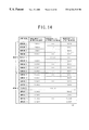
- FIG. 14 is a diagram showing a light wavelength array used in the embodiments of the present invention.
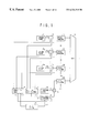
- FIG. 1 is a block diagram showing the principle of the present invention.
- Work light sources 11 - 1 - 11 - n respectively emit lights of wavelengths ⁇ x1- ⁇ xn.
- An optical four-wave mixing is performed so that a light ⁇ p emitted from a protection light source 52 is mixed with a branch light ⁇ xj which is one of the branch lights of the working light sources 11 - 1 - 11 - n , the branch light ⁇ xj having a predetermined relationship with the defective working light source 11 i ( ⁇ xi).
- the above mixing results in a substitute light ⁇ yi of the same wavelength as that of the faulty working light source ( ⁇ xi).
- the substitute light ⁇ yi is substituted for the transmission light ⁇ xi of the faulty light source.
- the substitute light ⁇ yi for the faulty light source 11 i is produced based on the branch light ⁇ xj of the normal working light source 11 j and the light ⁇ p of the protection light source 52 .
- the transmission system of the normal working light source 11 j is not affected at all.
- the substitute light ⁇ yi is produced by the optical four-wave mixing operation on the branch light ⁇ xj of the normal working light source 11 j and the protection light ⁇ p.
- the substitute light ⁇ yi is produced by the optical four-wave mixing operation on the branch light ⁇ xj of the normal working light source 11 j and the protection light ⁇ p.
- the light sources (dc light) are subjected to switching, it is not required to perform the switching control at high speed.
- the branch light ⁇ p of the protection light source 52 is used for a protection communication channel in a transmission path section. If a failure is detected in any of the working or active channels in the transmission path section, the main signal transmitted by the channel which becomes defective is transmitted using the branch light ⁇ p of the protection light source.
- the light of the protection light source can be used as not only a substitute light for the faulty working light source but also a substitute light for any of the working communication channels. As a result, the protection light source can efficiently be used.
- the wavelength of the protection light source is located in the center middle of an array of wavelengths of the working light sources arranged at constant intervals.
- the protection communication channel is located in the center of the optical transmission path passage wavelength band on the transmission path section.
- the substitute light is produced by using the following equation:
- ⁇ yi is the wavelength of the substitute light
- ⁇ xj is the wavelength of one of the working light sources having said given relationship with the faulty working light source.
- the WDM transmission apparatus comprises: working light sources 11 - 1 - 11 - n having different wavelengths ⁇ x1 ⁇ xn; a protection light source ( 52 ) having a wavelength ⁇ p different from those of the working light sources; photocouplers 12 - 1 - 12 - n which cause lights ⁇ x1 ⁇ xn from the working light sources to branch and add substitute lights ⁇ y1 ⁇ yn to optical transmission routes of the working light sources; a branch light selecting part 51 which selects one of branch lights from the photocouplers in accordance with a control signal S 1 externally supplied; a wavelength converting part 53 which produces the substitute lights ⁇ yi by optical four-wave mixing using the branch lights ⁇ xj from the photocouplers and the protection light ⁇ p from the protection light source; a substitute light delivery part 54 which deliver the substitute lights to the photocouplers; and a switching control part 60 which
- the WDM apparatus of (5) further comprises: a photocoupler 12 p which causes the protection light ⁇ p to branch; an optical modulator 13 p which modulates a branch protection light from the photocoupler by an electric main signal CHp; an optical multiplexer (MUX) 14 which multiplexes the branch protection light and signal lights from the working light sources and sends a multiplexed signal to a transmission path section, wherein the branch protection light is made to be modulated by a main signal CHi of a faulty channel which is one of working channels.
- MUX optical multiplexer
- the wavelength of the protection light source is located in a center of a wavelength array in which the wavelengths of the working light sources are arranged at equal intervals.
- the apparatus of (5) is configured so that the switching control part 60 produces the substitute light using the following equation:
- ⁇ xj is the wavelength of the faulty light source
- ⁇ xi is the wavelength of one of the branch lights to be selected by the branch light selecting part
- ⁇ p is the wavelength of the protection light source.
- the apparatus of (5) is configured so that the branch light selecting part 51 comprises, as shown in FIG. 4 A: a plurality of optical switches (OSW 1 ⁇ OSWn) turning ON/OFF the branch lights in accordance with an external control signal S 1 ; and an optical multiplexer (AWG) which multiplexes the branch lights from the optical switches.
- the branch light selecting part 51 comprises, as shown in FIG. 4 A: a plurality of optical switches (OSW 1 ⁇ OSWn) turning ON/OFF the branch lights in accordance with an external control signal S 1 ; and an optical multiplexer (AWG) which multiplexes the branch lights from the optical switches.
- the apparatus of (5) is configured so that the branch light selecting part 51 comprises, as shown in FIG. 4 B: an optical multiplexer (AWG) which multiplexes the branch lights; and a band-pass filter (BPF) which allows only one of the branch lights arranged in a multiplexed formation to pass therethrough.
- AMG optical multiplexer
- BPF band-pass filter
- apparatus of (5) comprises: an optical multiplexer (AGW) which multiplexes the branch lights; an optical fiber Bragg grating (FBG) which reflects only one of the branch lights arranged in a multiplexed formation in accordance with an external control signal S 1 ; and an optical circulator (OC) interposed between the optical multiplexer and the fiber Bragg grating.
- AGW optical multiplexer
- FBG optical fiber Bragg grating
- OC optical circulator
- the apparatus of (5) is configured so that the wavelength converting part 53 comprises a semiconductor optical amplifier (SOA) as an optical non-linear element for the optical four-wave mixing, as shown in FIG. 6 A.
- SOA semiconductor optical amplifier
- the apparatus of (5) is configured so that the wavelength converting part 53 comprises a dispersion shift fiber (DSF) as an optical non-linear element for the optical four-wave mixing, as shown in FIG. 6 B.
- DSF dispersion shift fiber
- the apparatus of (5) is configured so that the wavelength converting part 53 comprises a DFB laser diode (DFB-LD) as an optical non-linear element for the optical four-wave mixing, and a pump light ⁇ p generated in the DFB laser diode is used as a protection light source instead of the protection light source separately provided.
- DFB-LD DFB laser diode
- a pump light ⁇ p generated in the DFB laser diode is used as a protection light source instead of the protection light source separately provided.
- the protection light source 52 there is no need to separately provide the protection light source 52 , so that the circuit configuration can be simplified.
- the apparatus of (12) is configured so that the wavelength converting part 53 comprises a band-pass filter (BPF) which is provided on an output side of an optical non-linear element and which has a variable pass-band range controllable by an external control signal S 3 .
- BPF band-pass filter
- the apparatus of (5) is configured so that the switching control part 60 turns OFF adding of the substitute light ⁇ yi after the faulty working light source 11 - i is restored and starts to emit a light output. Hence, a breakdown of light does not take place, and non-breakdown switchback in data transmission can be achieved.
- the apparatus of (12) further comprises optical limiters (OLA) provided at output sides of the photocouplers 12 , the optical limiters causing the semiconductor optical amplifiers to operate in a gain saturation range.
- OVA optical limiters
- the apparatus of (12) comprises optical limiters (OLA) provided at output sides of the photocouplers, the optical limiters causing the semiconductor optical amplifiers which are rare-earth doped optical amplifiers (for example, erbium-doped optical fibers) to operate in a gain saturation range (the gain saturation ranges are defined for the respective wavelengths).
- OVA optical limiters
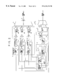
- FIG. 2 is a block diagram of a WDM transmission apparatus according to a first embodiment of the present invention.
- the transmission apparatus which is a WDM transmitter receiver, includes a transmitter part 10 , working light sources 11 - 1 - 11 - n , photocouplers 12 - 1 - 12 - n , optical modulators 13 - 1 - 13 - n , an optical multiplexer 14 , an optical amplifier (OA) 15 , an optical demultiplexer (DMUX) 16 , and a receiver part 17 .
- the transmitter part 10 modulates working lights of wavelengths ⁇ x1- ⁇ xn by electric signals CH 1 -CHn (on the order of giga bits) of respective channels.
- the working light sources 11 - 1 - 11 - n generate dc lights of the wavelengths ⁇ x1- ⁇ xn, respectively.
- Each of the photocouplers 12 - 1 - 12 - n splits the corresponding one of the working lights ⁇ x1- ⁇ xn into two components and combines the corresponding one of the substitute lights ⁇ y1- ⁇ yn with one of the two split components.
- the photocouplers 12 - 1 - 12 - n cause the lights from the working light sources 11 - 1 - 11 - n to branch and add substitute lights ⁇ y1- ⁇ yn to the optical transmission routes of the working light sources 11 - 1 - 11 - n .
- the optical modulators 13 - 1 - 13 - n are of the Mach-Zehnder type.
- the optical multiplexer 14 multiplexes signal lights of the wavelengths ⁇ x1- ⁇ xn.
- the optical amplifier 15 amplifies the multiplexed signal light.
- the optical demultiplexer 16 demultiplexes an input multiplexed signal light into signal lights of the wavelengths ⁇ x1- ⁇ xn.
- the receiver part 17 demodulates the signal lights of the wavelengths ⁇ x1- ⁇ xn to the electric signals CH 1 -CHn of the channels.
- the transmission apparatus includes a light spectrum analyzer 18 and the substitute light producing part 50 .
- the substitute light producing part 50 includes the branch light selecting part 51 , the protection source 52 , the wavelength converter 53 , and the substitute light delivery part 54 .
- the transmission apparatus includes a switching control part 60 , which controls a control bus 61 .
- the light spectrum analyzer 18 performs a spectrum analysis of the wavelengths ⁇ x1- ⁇ xn or the multiplexed signal light thereof. For example, the spectrum analysis supervises the light output levels and the wavelengths.
- the substitute light producing part 51 selects one ( ⁇ xj) of the branch lights of the wavelengths ⁇ x1- ⁇ xn in accordance with a control signal S 1 .
- the protection light source generates the protection light source (pump light source) of the fixed wavelength ⁇ p.
- the wavelength converter 53 produces the wavelength-converted substitute light (hereinafter, sometimes referred to as a four-wave mixed light or phase-conjugate light) ⁇ yi on the basis of an optical non-linear effect (an optical non-regenerate optical four-wave mixing) using the branch light ⁇ xj and the protection light ⁇ p.
- the substitute light delivery part 54 delivers the substitute light ⁇ p to the corresponding photocoupler 12 based on the wavelength of the input light to be replaced.
- the switching control part 60 includes a CPU, which performs the automatic redundant switch/switchback control for the working light sources, and a memory in which a control program describing the above control is stored.
- the electric main signals CH 1 -CHn are superimposed on the working lights ⁇ x1- ⁇ xn from the photocouplers 12 - 1 - 12 - n by the optical modulators 13 - 1 - 13 - n .
- the output lights of the photocouplers 12 - 1 - 12 - n are then transmitted to another remote party via the optical multiplexer 14 .
- the branch lights of the wavelengths ⁇ x1- ⁇ xn are applied to the branch light selecting part 51 , which selects one ( ⁇ xj) of them in accordance with the control signal S 1 from the switching control part 60 .
- the selected branch light ( ⁇ xj) is supplied to the wavelength converting part 53 .
- the photocouplers 12 - 1 - 12 - n are equipped with a light adding function, and receive the substitute lights ⁇ y1- ⁇ yn from the substitute light delivery part 54 when any of the working light sources becomes defective.
- the substitute light producing part 50 sends the dc light ⁇ p from the protection light source 52 to the wavelength converting part 53 .
- the wavelength converting part 53 generates the substitute light (four-wave mixed light/phase-conjugate light) ⁇ yi of the converted wavelength by thee non-degenerate optical four-wave mixing of the branch light ⁇ xj from the branch light selecting part 51 and the protection light ⁇ p from the protection light source 52 .
- the wavelength ⁇ yi of the substitute light satisfies the following equation:
- ⁇ p is the wavelength of the pump light (protection light) in the non-degenerate optical four-wave mixing
- ⁇ xj is the wavelength of the probe light (branch light).
- FIG. 14 shows a light wave array employed in the embodiments of the present invention.
- the following description is directed to a case where a light wave array of group 1 is employed.
- the wavelength ⁇ p is positioned in the center of the above light wave array.
- the above description can be applied to the group 2.
- the above light wave replacement is always vailable when the wavelengths of the light sources re arrayed at equal intervals and the wavelength of the protection light source is located in the center of the array.
- the light wave replacement does not depend on the numeral values of the wavelength intervals, and is maintained even when an increased number of wavelengths is used.
- the light wave replacement of the present invention can be applied to a wavelength array described in the proposed standard recommendations Gmcs (wavelength intervals of 0.8 nm) of ITU-T.
- Gmcs wavelength intervals of 0.8 nm
- the light wave replacement can be applied to, for instance, the 1.3 ⁇ 1.6 ⁇ n band.
- the substitute light ⁇ yi of the wavelength equal to the wavelength ⁇ xi of the faulty light source by the non-regenerate optical four-wave mixing carried out by the wavelength converting part 53 using the protection light ⁇ p and the corresponding one of the other normal working light sources.
- the substitute light ⁇ yi thus produced is applied to the photocoupler associated with the defective light source.
- the light spectrum analyzer 18 supervises the working channel lights (light output levels, wavelengths and so son) available in the multiplexer 14 . Provided that a failure in the wavelength ⁇ x2 of the working light source 11 - 2 is detected, the light spectrum analyzer 18 informs the switching control part 60 of detection of the above failure. Responsively, the switching control part 60 sends the control signal C 2 to the faulty light source 11 - 2 , which is caused to stop emitting the light output. Further, the switching control part 60 obtains, by the following expression, the wavelength ⁇ xj of the other normal working light source to be selected by the branch light selecting part 51 by using the wavelength ⁇ p of the protection light source 52 and the wavelength ⁇ x2 of the faulty light source 11 - 2 :
- the wavelength ⁇ x7 can also be obtained from the table shown in FIG. 14 .
- the switching control part 60 supplies the branch light selecting part 51 with the control signal S 1 for selecting the wavelength ⁇ x7.
- the branch light selecting part 51 selects the branch light wave ⁇ x7 from the working light source 11 - 7 .
- the substitute light ⁇ y2 (which has the same level as that of the working light wave ⁇ x2) is added to the photocoupler 12 - 2 associated with the faulty light source 11 - 2 via the substitute light delivery part 54 , and is then used as the substitute light source.
- the working light ⁇ x2 and the substitute light ⁇ y2 re temporarily combined at the photocoupler 12 - 2 .
- the light output level of the photocoupler 12 - 2 is temporarily doubled (3 dB up).
- the light output level of the photocoupler 12 - 2 does not break down, so that non-breakdown switchback in data transmissions can be realized.
- the supply of the substitute light ⁇ y2 is stopped, and only the restored light source 11 - 2 works.
- the light output of the photocoupler 12 - 2 returns to the standard level.
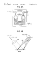
- FIGS. 3A and 3B are diagrams depicting the optical multiplexer/demultiplexer. More particularly, FIG. 3A shows a structure of the optical multiplexer/demultiplexer 14 / 16 using an arrayed-waveguide grating (AWG).
- AWG arrayed-waveguide grating
- the curvature centers of input and output slab waveguides are formed on a silicon substrate 14 ′ and are positioned in the centers of the waveguide ends of input/output waveguide groups.
- the array waveguide groups (AWG) are radially arranged so that the respective optical axes pass through the curvature centers.
- the slab waveguides and the array waveguide groups have an optical arrangement which is the same as a convex mirror and function as a lens. More particularly, multiplexed lights ⁇ 1 ⁇ n entering the input waveguides are spread by a diffraction in the input-side slab waveguide and drive the AWG waveguide group with the same phase.
- the waveguides of the AWG are spaced apart from each other so as not to be coupled with each other, and the respective lengths thereof are mutually different from each other by a constant value ⁇ L.
- the respective phases of the lights after propagation of the AWG waveguides obtained at the ends thereof mutually differ from each other by a constant value.
- the lights radiated from the ends of the AWG waveguides are diffracted in particular directions in which respective in-phase conditions satisfy taking into consideration the above-mentioned phase differences.
- single-color lights ⁇ 1 ⁇ n separated into the respective wavelengths are obtained at the ends of the output waveguides.
- FIG. 3B shows the light multiplexer/demultiplexer 14 / 16 using a reflection-type grating. Further, the light multiplexer/demultiplexer 14 / 16 can be configured by other various types of optical components.
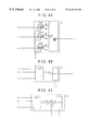
- FIGS. 4A, 4 B and 4 C are block diagrams of the branch light selecting part 51 used in the first embodiment of the present invention. More particularly, FIG. 4A shows a first structure of the branch light selecting part 51 .
- the input branch light waves ⁇ x1 ⁇ xn are applied to input ports of an AWG multiplexer via optical switches OSW 1 -OSWn of a directional coupler type.
- the switching control signal S 1 is normally OFF.
- the branch lights ⁇ x1 ⁇ xn are output to OFF-side terminals of the optical switches OSW 1 -OSWn. If necessary, the OFF-side terminals are terminated in the non-reflection fashion.
- the optical switches OSW 1 -OSWn may be formed of optical switches having different structures such as those of Mach-Zehnder type, total reflection type, asymmetry Y-branch type and optical gate type.
- FIG. 4B shows a second structure of the branch light selecting part 51 .
- the branch light waves ⁇ x1 ⁇ xn are combined by the AWG multiplexer, and a multiplexed light is output therefrom.
- a band-pass filter (BPF) allows only the wavelength ⁇ xj indicated by the control signal S 1 for wavelength selection externally supplied to pass therethrough.
- FIG. 4C shows a third structure of the branch light selecting part 51 .
- the branch light waves ⁇ x1 ⁇ xn are combined by the AWG multiplexer, and a multiplexed light is output therefrom. Further, the multiplexed light is applied to an input terminal a of an optical circulator OC, and is output via an output terminal b to a fiber Bragg grating (FBG) in which the wavelength to be reflected can be varied.
- the fiber Bragg grating FBG reflects only the particular wavelength (for example, ⁇ x1) dependent on the control signal S 1 .
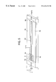
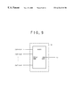
- FIG. 5 is a perspective view of a wavelength-variable filter (an acousto-optic tunable wavelength filter) used in the first embodiment of the present invention.
- the wavelength-variable filter shown in FIG. 5 includes an optical waveguide formed on an acousto-optic substrate, and a transducer which causes a surface acoustic wave (abbreviated as SAW) to be propagated through along the above optical waveguide so that the surface acoustic wave crosses the optical waveguide.
- SAW surface acoustic wave
- the surface acoustic wave can be controlled by an electric signal applied to the transducer.
- Various interactions can be produced in the light wave propagated through the optical waveguide under the surface acoustic wave (grating).
- a reference number 1 indicates an acousto-optical substrate made of a LiNbO 3 X-cut (Y-propagation) plate.
- Reference numbers 2 a and 2 b indicate high-concentration diffused regions, and a reference number 3 indicates a Ti-diffused optical waveguide (channel optical waveguide).
- a reference number 4 indicates a interdigital transducer (IDT) which drives the surface acoustic wave on the optical waveguide.
- Reference numbers 4 a and 4 b indicate comb electrodes formed of a thin film of a metal such as Al.
- Reference numbers 5 a and 5 b indicate SAW absorbers made of a soft substance such as wax or rubber.
- the rigid high-concentration Ti-diffused regions 2 a and 2 b are provided on opposing sides of the substrate 1 .
- the acoustic velocity is increased in the diffused regions 2 a and 2 b .
- SAW power is confined on the surface portion of the substrate 1 interposed between the regions 2 a and 2 b , so that the SAW drive power can be reduced.
- the use of the thermal diffusion method makes it possible to vary the refractive indexes no and ne of the normal and abnormal light beams by an approximately equal amount.
- the transducer 4 is mounted on one end (the light input side) of the substrate 1 , and an RF signal is applied across the comb electrodes 4 a and 4 b .
- the SAW can be produced by the piezoelectric performance of LiNbO 3 .
- the following expression stands:
- the SAW power produced in the substrate 1 is calculated by multiplying the RF signal power by an efficiency.
- the SAW traveling toward the light input side is absorbed by the absorber 5 a, and disappears immediately.
- the SAW traveling toward the light output side is propagated, at the acoustic velocity (phase speed), through the surface portion of the substrate 1 interposed between the regions 2 a and 2 b.
- a polarized wave of a TE-mode light (or TM-mode light) is applied to the waveguide input end, the polarized plane thereof is rotated by 90 degrees (adjustable by SAW power) at a given functional length L due to the elastic-optic effect caused by the SAW traveling through the waveguide.
- the polarized wave of the TE (or TM) mode is converted into that of the TM (or TE) mode.
- the absorber 5 b is provided in the above position, no interaction with the SAW takes place in the following portion of the waveguide 3 .
- the polarized wave of the TM (or TE) mode can be obtained at the waveguide output end.
- ⁇ TE and ⁇ TM are respectively propagation constants of the modes TE and TM, and N TE and N TM are respectively effective refractive indexes thereof, ⁇ is the wavelength of the SAW, f is the frequency thereof, and v is the phase speed thereof. That is, the mode conversion takes place due to the SAW of the frequency f satisfying the equation (1), and the conversion efficiency thereof can be controlled by the SAW power. Further, the following expression can be obtained from expression (1):
- of double refraction obtained when LiNbO 3 is used is approximately 0.072.
- ⁇ is nearly equal to 21.5 ⁇ m in order to produce the above-mentioned mode conversion with the light of the wavelength ⁇ of 1550 nm used in optical communications.
- the acoustic velocity v available on the substrate 1 is approximately 3700 m/s.
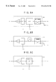
- FIGS. 6A, 6 B and 6 C are block diagrams of structures of the wavelength converting part used in the first embodiment of the present invention.
- FIG. 6A shows a first structure of the wavelength converting part in which a semiconductor optical amplifier (SOA) is used as a non-linear optical amplifier element of the wavelength converting part 53 .
- SOA semiconductor optical amplifier
- the protection light ⁇ p from the protection light source 52 and the branch light ⁇ p from the branch light selecting part 51 are combined by a photocoupler, and the combined light is applied to the semiconductor optical amplifier SOA.
- the protection light (pump light) is set to the linear polarization beforehand and that a polarization compensating part is provided in the optical path of the branch light ⁇ x in order to maintain the polarization plane of the branch light from the working light source in a fixed state.
- the branch light has the same polarization plane as that of the protection light.
- the polarization compensating part can be formed of a normal polarization compensating or polarization conservative filter.
- the phase-conjugate light wave ⁇ y of the wavelength satisfying the following expression can be obtained by the optical four-wave mixing of the protection light (pump light) ⁇ p and the branch light (signal light) ⁇ x:
- the lights of the wavelengths ⁇ y, ⁇ p and ⁇ x are input to the wavelength-variable band-pass filter BPF of the later stage.
- the filter BPF extracts only the phase-conjugate light ⁇ y in accordance with the wavelength select signal S 3 from the switching control part 60 .
- the phase-conjugate light ⁇ y thus extracted is amplified so as to have a given power (equal to the optical power of the working light source) by an optical amplifier OA, and is output to the outside of the wavelength converting part 53 .
- the output ON/OFF of the phase-conjugate light ⁇ y is controlled by turning ON/OFF the function of the semiconductor optical amplifier SOA or the output thereof in accordance with a control signal CS externally applied thereto.
- the semiconductor optical amplifier SOA is formed of an amplifier having an amplification band included in a given band located in the range of 1.3 ⁇ m-1.6 ⁇ m.
- FIG. 6B shows a second structure of the wavelength converting part 53 , in which a dispersion shift fiber DSF is used as the non-linear optical amplifier element.
- the phase-conjugate light (FWM light) of the wavelength ⁇ y having the following expression is obtained by the optical four-wave mixing of the protection light (pump light) ⁇ p and the branch light (signal light) ⁇ x:
- an optical switch (not shown for the sake of simplicity) is provided in order to implement output ON/OFF control of the phase-conjugate light ⁇ y. In this case, normally, the FWM light is inhibited from being output.
- the band-pass filter BPF is automatically tuned to the specified wavelength.
- the above optical switch can be implemented by an arrangement in which a normal switch is provided in series or loss in each wavelength of the BPF is controlled.
- the dispersion shift fiber DSF is formed of an optical fiber having a zero-dispersion wavelength in a given band in the range of 1.3 ⁇ m-1.6 ⁇ m.
- FIG. 6C shows a third structure of the wavelength converting part 53 , in which a distributed feedback laser diode (DFB-LD) is used as the non-linear optical amplifier element.
- DFB-LD distributed feedback laser diode
- the pump light ⁇ p can be generated therein.
- the protection light source 52 provided outside and the photocoupler provided inside can be omitted.
- the phase-conjugate light ⁇ y can be generated by the optical four-wave mixing of the protection light (pump light) ⁇ p and the branch light (signal light) ⁇ x:
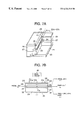
- FIG. 7A is a partially broken perspective view of the DFB-LD.
- an n-type InGaAsP guide layer 22 is formed on the upper surface of an n-type InP substrate 21 .
- a grating 23 of a wave shape is formed in the junction between the substrate 21 and the layer 22 in such a manner that the film thickness is periodically changed in the light traveling direction.
- the grating 23 has a phase shift structure in which he period is shifted by ⁇ ( ⁇ is the wavelength of the light in the waveguide structure) in a substantially center portion 23 c .
- an undoped multiquantum well (MQW) active layer 24 is formed on the guide layer 22 . Further, a p-type InGaAsP guide layer 25 and a p-type InP layer 26 are formed on the active layer 24 in this order.
- the layers from the p-type InP layer 26 to the upper portion of the n-type InP substrate 21 are patterned into a convex shape facing downwards, and the plane shape thereof is a stripe shape extending in the light traveling direction.
- p-type InP layer 27 and an n-type InP layer 28 are formed in this order at both sides of the convex portion of the stripe shape in the n-type InP substrate 21 .
- a p-type InGaAsP layer 29 is formed on the uppermost p-type InP layer 26 and n-type InP layer 28 .
- An n-side electrode 30 is formed on the lower surface of the p-type InP substrate 21 .
- three divided p-side electrodes 31 a , 31 b and 31 c are formed on the supper surface of the p-type InGaAsP layer 29 .
- FIG. 7B is a cross-sectional view taken along a line VII B —VII B shown in FIG. 7 A.
- the pump light ⁇ p is a pump light ⁇ p
- the input branch light ⁇ x is a probe light ⁇ s
- the phase-conjugate light ⁇ y is a phase-conjugate light ⁇ c.
- Non-reflection films 32 are coated on end surfaces 2 A and 2 B of the DFB-LD in order to cause the phase-conjugate light ⁇ c (four-wave mixed light) to pass therethrough.
- the resonator length thus structured is 900 ⁇ m
- the length of the p-side electrode 31 b located in the center is approximately 580 ⁇ m
- the lengths of the p-side electrodes 31 a and 31 c are approximately 160 ⁇ m.
- a drive current flows from the p-side electrodes 31 a - 31 c to the n-side electrode 30 vai the MQW active layer 24 .
- a continuous oscillation takes place in the MQW active layer so that the light of the wavelength 1549 nm is continuously generated at a power of 40 mW.
- a current of 400 mA is applied to the p-side electrodes 31 a - 31 c .
- the oscillated light is strongly confined in the DFB-LD due to the function of the two gratings 23 .
- the above oscillated light can be used as the pump light ⁇ p in the optical four-wave mixing.
- the non-reflection coating provided to the both ends of the end surfaces 2 A and 2 B causes light waves having different frequencies from that of the oscillated light ⁇ p to be reflected within the DFB-LD.
- the probe light (signal light) ⁇ s is supplied via the first pump end (end surface) 2 A
- the probe light ⁇ s, a part of the pump light ⁇ p and the phase-conjugate light ⁇ c are output via the second pump end (end surface) 2 B due to the non-regenerate optical four-wave mixing.
- the term “non-regenerate” is used as a meaning such that the wavelengths of the probe light ⁇ s and the pump light ⁇ p are different from each other.
- the intensity of the phase-conjugate light ⁇ c is proportional to the second power of the intensity of the pump light ⁇ p.
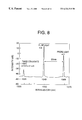
- FIG. 8 shows a spectrum of the output light of the DFB-LD by the non-regenerate optical four-wave mixing. It is known that the following equation stands among the angular frequency ⁇ s of the probe light, the angular frequency ⁇ p of the pump light, and the angular frequency ⁇ c of the phase-conjugate light:
- the single oscillation mode of the DFB-LD is changed by controlling the currents respectively flowing in the three p-side electrodes 31 a - 31 c to have different values.
- a drive circuit 40 shown in FIG. 7B controls the currents applied to the p-side electrodes 31 a and 31 c to have constant levels and increases the current applied to the p-side electrode 31 b .
- the oscillation wavelength shifts to the long wavelength side.
- the wavelength of the pump light ⁇ p for example, 1554 nm, 1563 nm.
- wavelength arrays as those of groups 1 and 2 shown in FIG. 14 .
- the DFB-LD can be used as one which has an amplification band located within a given band included in the range of 1.3 ⁇ m to 1.6 ⁇ m.
- FIG. 9 is a diagram of the substitute light delivery part 54 used in the first embodiment of the present invention.
- the input substitute light ⁇ y (which corresponds to, for example, the working light ⁇ x1) from the wavelength converting part 53 is output to only the output port for the substitute light ⁇ y1 by the AWG distributor and is then delivered to the corresponding photocoupler 12 -1.
- the above operation is carried out for each of the other substitute lights ⁇ y2- ⁇ yn.
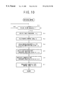
- FIG. 10 is a flowchart of the working light source switching control carried out in the first embodiment of the present invention. Normally, the process shown in FIG. 10 is performed after system power ON.
- a control signal Ci is supplied to the faulty working light source 11 i , which is controlled to stop the light output.
- the normal working wavelength ⁇ xj used to produce the substitute wavelength ⁇ yi is obtained by a computation or the table shown in FIG. 14 .
- the wavelength select signal S 1 is supplied to the branch light selecting part 51 , which thus selects the corresponding branch light ⁇ xj.
- the wavelength select signal S 3 is supplied to the wavelength converting part 53 , which thus extracts the corresponding FWM light ⁇ yi.
- the control signal CS is sent to the wavelength converting part 53 , which thus activates the optical four-wave mixing of the non-linear amplifier.
- the maintenance person is informed of the failure of the working light source 11 i . Responsively, the maintenance person takes off the faulty working light source 11 i and inserts a repaired or new source. Further, if necessary, the maintenance person checks the operation characteristics (the wavelength, light output level and so on). If there is no abnormality, the maintenance person depresses a restoration reset button (not shown for the sake of simplicity) for the replaced light source 11 i.
- FIG. 11 is a flowchart of a working light source switchback control carried out in the first embodiment of the present invention.
- the control process shown in FIG. 11 is started after switching of the faulty light source is performed.
- the control process waits for a restoration reset input related to the faulty working light source 11 i .
- the restoration reset input at step S 12 , the control signal Ci is supplied to the restored light source 11 I, which is turned ON to emit the light output.
- the restored light source 11 I which is turned ON to emit the light output.
- the optical limiter amplifier OLA shown in FIG. 2 is not provided.
- a linear optical amplifier OA is provided.
- the working light source 11 i is restored, the restored light ⁇ x1 and the substitute light ⁇ y1 are combined in the photocoupler 12 - 1 .
- the light input level of the optical modulator 13 - 1 is temporarily increased by 3 dB.
- an optical level variation of such a degree does not cause a harmful light serge to the later-stage optical components of the transmitter system and the optical system of the receiver side.
- the optical level variation of such a degree falls within a variation-resistance range of the normal transmitter and receiver systems, and the decoding of the main signals is not affected significantly. Thereafter, when the substitute light ⁇ y1 of the wavelength converting part 53 is stopped, the light input level of the optical modulator 13 - 1 is returned to the standard value.
- the optical limiter amplifier OLA shown in FIG. 2 is provided, or the linear optical amplifier OA is operated in the gain saturation range.
- the optical limiter amplifier OLA or the linear optical amplifier OA can be realized by selecting the performance of optical fiber amplifiers so that the gain saturation range is obtained in the respective wavelength bands. Alternatively, semiconductor optical amplifiers are driven so that the gain saturation range is obtained in the respective wavelength bands. Even if there is a 3 dB variation on the output side of the photocoupler 12 - 1 , such a variation is absorbed by the non-linear amplifying function of the OLA/OA, so that the light output power of the OLA/LA can be maintained at an approximately constant level. Thus, there is no possibility that an unbalance among the signal powers of the light signals ⁇ x1 ⁇ xn occurs. As a result, data communications in the switchback section can continue with a high reliability.
- the control signal CS is supplied to the wavelength converting part 53 at step S 15 .
- the optical four-wave mixing of the non-linear optical amplifier or the outputting of the substitute light is disabled.
- an instantaneous breakdown does not occur in the input light applied to the optical modulator 13 even by any of the above switch-back formations, so that non-breakdown switchback can be realized.
- the switching control part 60 enters the redundant switching control shown in FIG. 10 .
- the backup using the substitute light and switchback to the restored light source can automatically be performed.
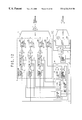
- FIG. 12 is a block diagram of a WDM transmission transmitter receiver according to a second embodiment of the present invention.
- the protection light ⁇ p of the protection light source 52 (or the DFB-LD) is used not only to produce the substitute light but also to a communication light wave ⁇ p of a protection channel via which the main signal is transferred over the transmission path between the apparatus of interest and the remote station or office.
- the basic structure and operation of the WDM transmitter receiver according to the second embodiment of the present invention is the same as that of the WDM transmitter receiver according to the first embodiment thereof.
- the first and second embodiments of the present invention differ from each other in that an optical modulator 13 - p is newly provided in FIG.
- the optical modulator 13 - p modulates the protection light ⁇ p after branching by an electric signal CHp of the protection channel.
- the light signal of the protection channel is multiplexed with the other lights by the multiplexer 14 .
- the receiver system shown in FIG. 12 includes a structure for performing a receive process for the light signal of the protection channel.
- the protection communication channel ⁇ p is provided on the optical transmission path.
- the working channel lights such as ⁇ x1 and ⁇ xn are located in the both shoulder portions of the communication band.
- the second embodiment of the present invention it is possible to switch the working channel light ⁇ x1 or ⁇ xn with the degraded error rate to the protection channel light ⁇ p located in the center of the wavelength pass band. Thus, it is possible to provide high-quality protection communication channel.
- failure notification information is transmitted via the maintenance channel from the remote office.
- the office which receives the failure notification information it is determined that the notified failure is a failure that occurs in the transmission path section if the light transmission level (wavelength, light output level) of the own office. Then, the main signal of the faulty channel is connected to and transmitted via the protection channel.
- the automatic switch/switchback control between the working and protection channels performed by the channel switching control part 60 can be implemented by an automatic switch/switchback control using APS (automatic Protection Switch) bytes (K 1 , K 2 ) in the SDH (Synchronous Digital Hierarchy system.
- APS automatic Protection Switch
- SDH Synchronous Digital Hierarchy system
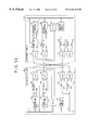
- FIG. 13 is a block diagram of a WDM transmitter receiver according to a third embodiment of the present invention.
- parts that are the same as those shown in the previously described figures are given the same reference numbers.
- a plurality of redundant configurations each of which is the n:1 redundant configuration used in the first and second embodiments of the present invention, are provided in parallel to a plurality of bands.
- 100 A and 100 B indicate WDM transmitter receiver
- 10 - 1 and 10 - 2 indicate first and second transmitter parts
- 14 - 1 and 14 - 2 indicate first and second optical multiplexers
- 16 - 1 and 16 - 2 indicate first and second optical demultiplexers
- 17 - 1 and 17 - 2 indicate first and second receiver parts
- 50 - 1 and 50 - 2 indicate first and second substitute light producing parts
- 18 indicates a light spectrum analyzer (SPAN)
- SPSN light spectrum analyzer
- 60 indicates a switching control part.
- Each of the above parts is the same as the corresponding part which has been described in the first and second embodiments of the present invention.
- FIG. 14 shows the light wave array also applied to the third embodiment of the present invention.
- the light wave array has two redundant systems of the first and second groups, each of which groups is configured so that the automatic switch/switchback control of the 8 (working):1 (protection) redundant configuration is available.
- 8 (working):1 (protection) redundant configuration is available.
- the four-wave mixed light ⁇ yi is obtained by the following expression in which the protection light ⁇ p is used as a pump light:
- the four-wave mixed light ⁇ yi may be produced by the following expression in which the branch light ⁇ xj is used as a pump light:
- the present invention it is possible to perform, with the simple redundant configuration, the automatic switch/switchback control of the light sources with high reliability and low cost. This greatly contributes to the spread of the WDM transmission system and improvements in the reliability thereof.
Landscapes
- Engineering & Computer Science (AREA)
- Computer Networks & Wireless Communication (AREA)
- Signal Processing (AREA)
- Optical Communication System (AREA)
- Optical Integrated Circuits (AREA)
- Optical Modulation, Optical Deflection, Nonlinear Optics, Optical Demodulation, Optical Logic Elements (AREA)
- Semiconductor Lasers (AREA)
Applications Claiming Priority (2)
| Application Number | Priority Date | Filing Date | Title |
|---|---|---|---|
| JP10-355469 | 1998-12-15 | ||
| JP35546998A JP3605629B2 (ja) | 1998-12-15 | 1998-12-15 | 光源の冗長切替方法及び該方法による波長多重伝送装置 |
Publications (1)
| Publication Number | Publication Date |
|---|---|
| US6324318B1 true US6324318B1 (en) | 2001-11-27 |
Family
ID=18444136
Family Applications (1)
| Application Number | Title | Priority Date | Filing Date |
|---|---|---|---|
| US09/459,886 Expired - Lifetime US6324318B1 (en) | 1998-12-15 | 1999-12-14 | Redundant optical source switching method and wavelength division multiplexing transmission apparatus using the same |
Country Status (2)
| Country | Link |
|---|---|
| US (1) | US6324318B1 (ja) |
| JP (1) | JP3605629B2 (ja) |
Cited By (36)
| Publication number | Priority date | Publication date | Assignee | Title |
|---|---|---|---|---|
| US20020067890A1 (en) * | 2000-12-06 | 2002-06-06 | Shigeru Yoneda | Arrayed waveguide grating, arrayed waveguide grating module, arraued waveguide grating module waveguide compensation method, optical communication system |
| US6434286B2 (en) * | 2000-05-29 | 2002-08-13 | Hitachi, Ltd. | Optical signal switching apparatus |
| US20030048503A1 (en) * | 2001-03-27 | 2003-03-13 | Osamu Aso | Multi-frequency light source |
| US20030118294A1 (en) * | 2001-12-04 | 2003-06-26 | Tsuguhiro Korenaga | Optical package substrate, optical device, optical module, and method for molding optical package substrate |
| US6665113B2 (en) * | 1999-12-28 | 2003-12-16 | The Furukawa Electric Company, Ltd. | Wavelength converter and wavelength division multiplexing transmission method using same |
| US6683896B2 (en) * | 2000-11-06 | 2004-01-27 | Vitesse Semiconductor Corporation | Method of controlling the turn off characteristics of a VCSEL diode |
| US20040047541A1 (en) * | 2002-09-10 | 2004-03-11 | Sumitomo Electric Industries, Ltd. | Optical switch for switching between multiple main light emitters |
| WO2004068765A1 (de) * | 2003-01-28 | 2004-08-12 | Marconi Communications Gmbh | Ausgangsstufe fur die wdm-nachrichtenubertragung und verfahren zum austauschen von fullichtquellen in einer solchen ausgangsstufe |
| US20040184807A1 (en) * | 1999-12-28 | 2004-09-23 | Osamu Aso | Wavelength converter and wavelength division multiplexing transmission method using same |
| WO2004068268A3 (de) * | 2003-01-28 | 2004-10-07 | Marconi Comm Gmbh | Sender und verfahren zur nachrichtenübertragung auf einer optischen faser |
| US20050008362A1 (en) * | 2003-07-07 | 2005-01-13 | Dae-Kwang Jung | Self-healing wavelength division multiplexing-passive optical network system |
| US20050099941A1 (en) * | 2003-11-12 | 2005-05-12 | Alcatel | Trail/path protection for SDH/SONET networks |
| US20050191052A1 (en) * | 2004-02-26 | 2005-09-01 | Karl Schrodinger | Optical emission module |
| US20050213972A1 (en) * | 2004-03-29 | 2005-09-29 | Fujitsu Limited | Light source apparatus, and method for switching redundancy of the light source |
| US20050259990A1 (en) * | 2004-05-20 | 2005-11-24 | Fujitsu Limited | Optical transmission system |
| US6980743B1 (en) * | 2001-05-18 | 2005-12-27 | Juniper Networks, Inc. | Transparent wavelength division multiplexing |
| US20060216027A1 (en) * | 2005-03-23 | 2006-09-28 | Fujitsu Limited | Wavelength division multiplexing transmission apparatus using a multiple wavelength light source |
| US20070018200A1 (en) * | 2000-10-11 | 2007-01-25 | Corbett Brian M | Single frequency laser |
| US7212738B1 (en) * | 2002-08-01 | 2007-05-01 | Finisar Corporation | Preventing signal loss in an optical communications network |
| US20080239297A1 (en) * | 2005-06-17 | 2008-10-02 | Rueb Kurt D | Multiple head laser projector and method |
| WO2009117822A1 (en) * | 2008-03-28 | 2009-10-01 | Nortel Networks Limited | Protected light source for multiple wavelength division multiplexed passive optical networks (wdm-pons) |
| US7831151B2 (en) * | 2001-06-29 | 2010-11-09 | John Trezza | Redundant optical device array |
| US20110170856A1 (en) * | 2010-01-08 | 2011-07-14 | Fujitsu Optical Components Limited | Optical transmission device |
| US20130004166A1 (en) * | 2010-06-24 | 2013-01-03 | Mitsubishi Electric Corporation | Wavelength-division multiplexing transmission device |
| US20150381277A1 (en) * | 2014-06-30 | 2015-12-31 | Fujitsu Limited | Optical transmission system, transmitter, receiver, and optical transmission method |
| US20170019167A1 (en) * | 2015-07-17 | 2017-01-19 | Fujitsu Limited | Optical transmission device and protection wavelength selection method |
| US20170075064A1 (en) * | 2015-09-16 | 2017-03-16 | Technobis Group B. V. | Fiber bragg grating interrogator assembly and method for the same |
| CN109212663A (zh) * | 2017-07-06 | 2019-01-15 | 三星电子株式会社 | 光子集成电路和光学发送器 |
| US10277327B2 (en) * | 2016-12-28 | 2019-04-30 | Calix Inc. | Methods and apparatus for improving reliability of an optical device using auxiliary lasers in a photonic integrated circuit |
| US10623090B2 (en) * | 2018-05-24 | 2020-04-14 | At&T Intellectual Property I, L.P. | Multi-lane optical transport network recovery |
| EP3672113A1 (en) * | 2018-12-21 | 2020-06-24 | Fujitsu Limited | Wavelength conversion device and excitation light switching method |
| US10718899B2 (en) | 2018-03-30 | 2020-07-21 | Fujikura Ltd. | Optical device, wavelength division multiplexing transmitter, wavelength division multiplexing receiver, and wavelength division multiplexing transmission and receiving system |
| US20200244388A1 (en) * | 2016-12-20 | 2020-07-30 | Xieon Networks S.À.R.L. | Subcarrier diversity in optical communication systems |
| WO2020244302A1 (zh) * | 2019-06-03 | 2020-12-10 | 华为技术有限公司 | 光源切换方法和装置 |
| US11218222B1 (en) * | 2020-07-31 | 2022-01-04 | At&T Intellectual Property I, L.P. | Method and an apparatus for transitioning between optical networks |
| US11468309B1 (en) * | 2019-03-07 | 2022-10-11 | Miguel Alberto Adan | Wave interaction processor |
Families Citing this family (9)
| Publication number | Priority date | Publication date | Assignee | Title |
|---|---|---|---|---|
| WO2002035742A1 (en) * | 2000-10-24 | 2002-05-02 | Telefonaktiebolaget Lm Ericsson (Publ) | Use of opa for switching and routing in wdm networks |
| JP2004533150A (ja) * | 2001-03-16 | 2004-10-28 | フォトゥリス,インク | 再構成可能な光スイッチ及びバックアップチューナブルレーザ送信機を備える波長多重光通信システム |
| CA2379285A1 (en) * | 2001-03-27 | 2002-09-27 | The Furukawa Electric Co., Ltd | Multi-frequency light source |
| DE60234795D1 (de) * | 2001-06-29 | 2010-02-04 | Sumitomo Electric Industries | Pumplichtquelleneinheit, Ramanverstärker und optisches Übertragungssystem |
| JP4593131B2 (ja) * | 2004-03-05 | 2010-12-08 | 古河電気工業株式会社 | 光送信器、光送信システムおよび出力制御方法 |
| JP4517747B2 (ja) * | 2004-06-28 | 2010-08-04 | 日本電気株式会社 | 波長多重伝送装置並びにその波長増設方法 |
| JP4569761B2 (ja) * | 2005-03-08 | 2010-10-27 | 日本電気株式会社 | 光送信器、光伝送システム、および光中継器 |
| JP5503266B2 (ja) * | 2009-11-26 | 2014-05-28 | 古河電気工業株式会社 | 多値光位相変調器 |
| JP6266025B2 (ja) * | 2014-01-30 | 2018-01-24 | 三菱電機株式会社 | ビーム結合装置 |
Citations (8)
| Publication number | Priority date | Publication date | Assignee | Title |
|---|---|---|---|---|
| US5113459A (en) * | 1990-01-30 | 1992-05-12 | Pirelli Cavi S.P.A. | Optical fiber telecommunication line with separate, optically transmitted service channels |
| US5173957A (en) * | 1991-09-12 | 1992-12-22 | At&T Bell Laboratories | Pump redundancy for optical amplifiers |
| US5633741A (en) * | 1995-02-23 | 1997-05-27 | Lucent Technologies Inc. | Multichannel optical fiber communications |
| US5731887A (en) * | 1995-12-22 | 1998-03-24 | Mci Communications Corporation | System and method for photonic facility and line protection switching |
| US5739935A (en) * | 1995-11-14 | 1998-04-14 | Telefonaktiebolaget Lm Ericsson | Modular optical cross-connect architecture with optical wavelength switching |
| US5742416A (en) * | 1996-03-28 | 1998-04-21 | Ciena Corp. | Bidirectional WDM optical communication systems with bidirectional optical amplifiers |
| US5777761A (en) * | 1995-12-22 | 1998-07-07 | Mci Communications Corporation | System and method for photonic facility and line protection switching using wavelength translation |
| US6005694A (en) * | 1995-12-28 | 1999-12-21 | Mci Worldcom, Inc. | Method and system for detecting optical faults within the optical domain of a fiber communication network |
-
1998
- 1998-12-15 JP JP35546998A patent/JP3605629B2/ja not_active Expired - Fee Related
-
1999
- 1999-12-14 US US09/459,886 patent/US6324318B1/en not_active Expired - Lifetime
Patent Citations (9)
| Publication number | Priority date | Publication date | Assignee | Title |
|---|---|---|---|---|
| US5113459A (en) * | 1990-01-30 | 1992-05-12 | Pirelli Cavi S.P.A. | Optical fiber telecommunication line with separate, optically transmitted service channels |
| US5113459C1 (en) * | 1990-01-30 | 2001-10-23 | Pirelli Cavi Spa | Optical fiber telecommunication line with separate optically transmitted service channels |
| US5173957A (en) * | 1991-09-12 | 1992-12-22 | At&T Bell Laboratories | Pump redundancy for optical amplifiers |
| US5633741A (en) * | 1995-02-23 | 1997-05-27 | Lucent Technologies Inc. | Multichannel optical fiber communications |
| US5739935A (en) * | 1995-11-14 | 1998-04-14 | Telefonaktiebolaget Lm Ericsson | Modular optical cross-connect architecture with optical wavelength switching |
| US5731887A (en) * | 1995-12-22 | 1998-03-24 | Mci Communications Corporation | System and method for photonic facility and line protection switching |
| US5777761A (en) * | 1995-12-22 | 1998-07-07 | Mci Communications Corporation | System and method for photonic facility and line protection switching using wavelength translation |
| US6005694A (en) * | 1995-12-28 | 1999-12-21 | Mci Worldcom, Inc. | Method and system for detecting optical faults within the optical domain of a fiber communication network |
| US5742416A (en) * | 1996-03-28 | 1998-04-21 | Ciena Corp. | Bidirectional WDM optical communication systems with bidirectional optical amplifiers |
Cited By (73)
| Publication number | Priority date | Publication date | Assignee | Title |
|---|---|---|---|---|
| US6665113B2 (en) * | 1999-12-28 | 2003-12-16 | The Furukawa Electric Company, Ltd. | Wavelength converter and wavelength division multiplexing transmission method using same |
| US7061664B2 (en) | 1999-12-28 | 2006-06-13 | The Furukawa Electric Co., Ltd. | Wavelength converter and wavelength division multiplexing transmission method using the same |
| US20040184807A1 (en) * | 1999-12-28 | 2004-09-23 | Osamu Aso | Wavelength converter and wavelength division multiplexing transmission method using same |
| US6434286B2 (en) * | 2000-05-29 | 2002-08-13 | Hitachi, Ltd. | Optical signal switching apparatus |
| US20070018200A1 (en) * | 2000-10-11 | 2007-01-25 | Corbett Brian M | Single frequency laser |
| US6683896B2 (en) * | 2000-11-06 | 2004-01-27 | Vitesse Semiconductor Corporation | Method of controlling the turn off characteristics of a VCSEL diode |
| US6690861B2 (en) * | 2000-12-06 | 2004-02-10 | Nec Corporation | Arrayed waveguide grating, arrayed waveguide grating module, arrayed waveguide grating module waveguide compensation method, optical communication system |
| US20020067890A1 (en) * | 2000-12-06 | 2002-06-06 | Shigeru Yoneda | Arrayed waveguide grating, arrayed waveguide grating module, arraued waveguide grating module waveguide compensation method, optical communication system |
| US6810180B2 (en) | 2000-12-06 | 2004-10-26 | Nec Corporation | Arrayed waveguide grating, arrayed waveguide grating module, arrayed waveguide grating module waveguide compensation method, optical communication system |
| US20040067019A1 (en) * | 2000-12-06 | 2004-04-08 | Shigeru Yoneda | Arrayed waveguide grating, arrayed waveguide grating module, arraued waveguide grating module waveguide compensation method, optical communication system |
| US20030048503A1 (en) * | 2001-03-27 | 2003-03-13 | Osamu Aso | Multi-frequency light source |
| US7408701B2 (en) | 2001-03-27 | 2008-08-05 | The Furukawa Electric Co., Ltd. | Multi-frequency light source |
| US20060193032A1 (en) * | 2001-03-27 | 2006-08-31 | The Furukawa Electric Co., Ltd. | Multi-frequency light source |
| US7054057B2 (en) * | 2001-03-27 | 2006-05-30 | The Furukawa Electric Co., Ltd. | Multi-frequency light source |
| US6980743B1 (en) * | 2001-05-18 | 2005-12-27 | Juniper Networks, Inc. | Transparent wavelength division multiplexing |
| US7831151B2 (en) * | 2001-06-29 | 2010-11-09 | John Trezza | Redundant optical device array |
| US20050157989A1 (en) * | 2001-12-04 | 2005-07-21 | Tsuguhiro Korenaga | Optical package substrate, optical device, optical module, and method for molding optical package substrate |
| US6904190B2 (en) * | 2001-12-04 | 2005-06-07 | Matsushita Electric Industrial Co., Ltd. | Optical package substrate, optical device, optical module, and method for molding optical package substrate |
| US20030118294A1 (en) * | 2001-12-04 | 2003-06-26 | Tsuguhiro Korenaga | Optical package substrate, optical device, optical module, and method for molding optical package substrate |
| US7212738B1 (en) * | 2002-08-01 | 2007-05-01 | Finisar Corporation | Preventing signal loss in an optical communications network |
| US6868198B2 (en) * | 2002-09-10 | 2005-03-15 | Sumitomo Electric Industries, Ltd. | Optical switch for switching between multiple main light emitters |
| US20040047541A1 (en) * | 2002-09-10 | 2004-03-11 | Sumitomo Electric Industries, Ltd. | Optical switch for switching between multiple main light emitters |
| WO2004068765A1 (de) * | 2003-01-28 | 2004-08-12 | Marconi Communications Gmbh | Ausgangsstufe fur die wdm-nachrichtenubertragung und verfahren zum austauschen von fullichtquellen in einer solchen ausgangsstufe |
| US20060263089A1 (en) * | 2003-01-28 | 2006-11-23 | Cornelius Furst | Output stage for carrying out wdm message transmission and methods for exchanging full light sources in an output stage of this type |
| WO2004068268A3 (de) * | 2003-01-28 | 2004-10-07 | Marconi Comm Gmbh | Sender und verfahren zur nachrichtenübertragung auf einer optischen faser |
| US7822345B2 (en) | 2003-01-28 | 2010-10-26 | Ericsson Ab | Output stage for carrying out WDM message transmission and methods for exchanging full light sources in an output stage of this type |
| US20060177221A1 (en) * | 2003-01-28 | 2006-08-10 | Marconi Communitions Gmbh | Transmitter and method for transmitting messages on an optical fiber |
| US7738791B2 (en) | 2003-01-28 | 2010-06-15 | Ericsson, Ab | Transmitter and method for transmitting messages on an optical fiber |
| EP1496634A3 (en) * | 2003-07-07 | 2006-05-17 | Samsung Electronics Co., Ltd. | Self-healing wavelength division multiplexing passive optical network system |
| US20050008362A1 (en) * | 2003-07-07 | 2005-01-13 | Dae-Kwang Jung | Self-healing wavelength division multiplexing-passive optical network system |
| US7283748B2 (en) | 2003-07-07 | 2007-10-16 | Samsung Electronics Co., Ltd. | Self-healing wavelength division multiplexing-passive optical network system |
| US7630297B2 (en) * | 2003-11-12 | 2009-12-08 | Alcatel | Trail/path protection for SDH/SONET networks |
| US20050099941A1 (en) * | 2003-11-12 | 2005-05-12 | Alcatel | Trail/path protection for SDH/SONET networks |
| US20050191052A1 (en) * | 2004-02-26 | 2005-09-01 | Karl Schrodinger | Optical emission module |
| EP1583259A3 (en) * | 2004-03-29 | 2006-02-01 | Fujitsu Limited | Light source apparatus, and method for switching redundancy of the light source |
| US20050213972A1 (en) * | 2004-03-29 | 2005-09-29 | Fujitsu Limited | Light source apparatus, and method for switching redundancy of the light source |
| US7447446B2 (en) | 2004-03-29 | 2008-11-04 | Fujitsu Limited | Light source apparatus, and method for switching redundancy of the light source |
| US20050259990A1 (en) * | 2004-05-20 | 2005-11-24 | Fujitsu Limited | Optical transmission system |
| US7146071B2 (en) * | 2004-05-20 | 2006-12-05 | Fujitsu Limited | Optical transmission system |
| US7623787B2 (en) | 2005-03-23 | 2009-11-24 | Fujitsu Limited | Wavelength division multiplexing transmission apparatus using a multiple wavelength light source |
| US20060216027A1 (en) * | 2005-03-23 | 2006-09-28 | Fujitsu Limited | Wavelength division multiplexing transmission apparatus using a multiple wavelength light source |
| US20080239297A1 (en) * | 2005-06-17 | 2008-10-02 | Rueb Kurt D | Multiple head laser projector and method |
| WO2009117822A1 (en) * | 2008-03-28 | 2009-10-01 | Nortel Networks Limited | Protected light source for multiple wavelength division multiplexed passive optical networks (wdm-pons) |
| US20110170856A1 (en) * | 2010-01-08 | 2011-07-14 | Fujitsu Optical Components Limited | Optical transmission device |
| US20130004166A1 (en) * | 2010-06-24 | 2013-01-03 | Mitsubishi Electric Corporation | Wavelength-division multiplexing transmission device |
| US8805185B2 (en) * | 2010-06-24 | 2014-08-12 | Mitsubishi Electric Corporation | Wavelength-division multiplexing transmission device |
| US20150381277A1 (en) * | 2014-06-30 | 2015-12-31 | Fujitsu Limited | Optical transmission system, transmitter, receiver, and optical transmission method |
| US9906306B2 (en) * | 2014-06-30 | 2018-02-27 | Fujitsu Limited | Optical transmission system, transmitter, receiver, and optical transmission method |
| US20170019167A1 (en) * | 2015-07-17 | 2017-01-19 | Fujitsu Limited | Optical transmission device and protection wavelength selection method |
| US9800326B2 (en) * | 2015-07-17 | 2017-10-24 | Fujitsu Limited | Optical transmission device and protection wavelength selection method |
| US10247880B2 (en) * | 2015-09-16 | 2019-04-02 | Technobis Group B. V. | Fiber Bragg grating interrogator assembly and method for the same |
| US20170075064A1 (en) * | 2015-09-16 | 2017-03-16 | Technobis Group B. V. | Fiber bragg grating interrogator assembly and method for the same |
| US11088775B2 (en) * | 2016-12-20 | 2021-08-10 | Xieon Networks S.A.R.L. | Subcarrier diversity in optical communication systems |
| US20200244388A1 (en) * | 2016-12-20 | 2020-07-30 | Xieon Networks S.À.R.L. | Subcarrier diversity in optical communication systems |
| US10277327B2 (en) * | 2016-12-28 | 2019-04-30 | Calix Inc. | Methods and apparatus for improving reliability of an optical device using auxiliary lasers in a photonic integrated circuit |
| US10374699B2 (en) * | 2017-07-06 | 2019-08-06 | Samsung Electronics Co., Ltd. | Photonic integrated circuit and optical transmitter |
| CN109212663A (zh) * | 2017-07-06 | 2019-01-15 | 三星电子株式会社 | 光子集成电路和光学发送器 |
| CN109212663B (zh) * | 2017-07-06 | 2020-08-25 | 三星电子株式会社 | 光子集成电路和光学发送器 |
| US10718899B2 (en) | 2018-03-30 | 2020-07-21 | Fujikura Ltd. | Optical device, wavelength division multiplexing transmitter, wavelength division multiplexing receiver, and wavelength division multiplexing transmission and receiving system |
| US10826602B2 (en) | 2018-05-24 | 2020-11-03 | At&T Intellectual Property I, L.P. | Multi-lane optical transport network recovery |
| US10623090B2 (en) * | 2018-05-24 | 2020-04-14 | At&T Intellectual Property I, L.P. | Multi-lane optical transport network recovery |
| US11243349B2 (en) * | 2018-12-21 | 2022-02-08 | Fujitsu Limited | Wavelength conversion device and excitation light switching method |
| EP3672113A1 (en) * | 2018-12-21 | 2020-06-24 | Fujitsu Limited | Wavelength conversion device and excitation light switching method |
| CN111355555A (zh) * | 2018-12-21 | 2020-06-30 | 富士通株式会社 | 波长转换装置和激发光切换方法 |
| US11468309B1 (en) * | 2019-03-07 | 2022-10-11 | Miguel Alberto Adan | Wave interaction processor |
| WO2020244302A1 (zh) * | 2019-06-03 | 2020-12-10 | 华为技术有限公司 | 光源切换方法和装置 |
| US11877368B2 (en) | 2019-06-03 | 2024-01-16 | Huawei Technologies Co., Ltd. | Optical source switching method and apparatus |
| US12156310B2 (en) | 2019-06-03 | 2024-11-26 | Huawei Technologies Co., Ltd. | Optical source switching method and apparatus |
| US20220085893A1 (en) * | 2020-07-31 | 2022-03-17 | At&T Intellectual Property I, L.P. | Method and an apparatus for transitioning between optical networks |
| US11218222B1 (en) * | 2020-07-31 | 2022-01-04 | At&T Intellectual Property I, L.P. | Method and an apparatus for transitioning between optical networks |
| US11626927B2 (en) * | 2020-07-31 | 2023-04-11 | At&T Intellectual Property I, L.P. | Method and an apparatus for transitioning between optical networks |
| US12009866B2 (en) * | 2020-07-31 | 2024-06-11 | At&T Intellectual Property I, L.P. | Method and an apparatus for transitioning between optical networks |
| US12348272B2 (en) * | 2020-07-31 | 2025-07-01 | At&T Intellectual Property I, L.P. | Method and an apparatus for transitioning between optical networks |
Also Published As
| Publication number | Publication date |
|---|---|
| JP3605629B2 (ja) | 2004-12-22 |
| JP2000183817A (ja) | 2000-06-30 |
Similar Documents
| Publication | Publication Date | Title |
|---|---|---|
| US6324318B1 (en) | Redundant optical source switching method and wavelength division multiplexing transmission apparatus using the same | |
| JP3639109B2 (ja) | 光伝送装置、光伝送システム及び光端局 | |
| EP0591042B1 (en) | Arrayed-wave guide grating multi/demultiplexer with loop-back optical paths | |
| US6437888B1 (en) | Device for adding and dropping optical signals | |
| US6822980B2 (en) | Tunable semiconductor laser with integrated wideband reflector | |
| JP2009044734A (ja) | 再構成可能な光スイッチ及びバックアップチューナブルレーザ送信機を備える波長多重光通信システム | |
| US6856455B2 (en) | Light source apparatus, optical amplifier and optical communication system | |
| US6693925B2 (en) | Modulatable multi-wavelength fiber laser source | |
| US6674773B1 (en) | Multi-wavelength Raman laser | |
| US6748176B1 (en) | Optical dropping apparatus and optical add/drop multiplexer | |
| US12057888B2 (en) | Laser light system with wavelength attenuation | |
| US7019907B2 (en) | Integrated lithium niobate based optical transmitter | |
| JP3293698B2 (ja) | ループバック光路付アレイ導波路回折格子型光合分波器 | |
| JP4156562B2 (ja) | 光伝送装置、光伝送システム及び光端局 | |
| JP7370097B1 (ja) | 変調器、変調システム、及び送信モジュール | |
| Ikegami | WDM Devices, State of the Art | |
| Chang | Advanced tunable optical filter for fiber optic communication network | |
| Dong et al. | All-fiber photonic devices and system for advanced optical communications | |
| JP4348388B2 (ja) | 光伝送装置、光伝送システム及び光端局 | |
| JP2004320797A (ja) | 光伝送装置、光伝送システム及び光端局 | |
| Tian et al. | Novel fully dynamic and reconfigurable optical add/drop multiplexer based on AOTF with low crosstalk | |
| WO2002011332A2 (en) | Wavelength selectable optical add-drop multiplexer | |
| JP2000235202A (ja) | 波長変換装置及び信号光発生装置 | |
| Fu et al. | Novel grating-in-etalon WDM device and a proof-of-concept demonstration of a 1/spl times/40 WDM in LiNbO/sub 3 | |
| JPS62206531A (ja) | 波長多重光交換回路 |
Legal Events
| Date | Code | Title | Description |
|---|---|---|---|
| AS | Assignment |
Owner name: FUJITSU LIMITED, JAPAN Free format text: ASSIGNMENT OF ASSIGNORS INTEREST;ASSIGNOR:SUZUKI, YASUO;REEL/FRAME:010467/0830 Effective date: 19991210 |
|
| STCF | Information on status: patent grant |
Free format text: PATENTED CASE |
|
| FPAY | Fee payment |
Year of fee payment: 4 |
|
| FPAY | Fee payment |
Year of fee payment: 8 |
|
| FPAY | Fee payment |
Year of fee payment: 12 |