US6255916B1 - Resonator-type surface-acoustic-wave filter for reducing the signal strength of a spurious peak - Google Patents
Resonator-type surface-acoustic-wave filter for reducing the signal strength of a spurious peak Download PDFInfo
- Publication number
- US6255916B1 US6255916B1 US08/598,137 US59813796A US6255916B1 US 6255916 B1 US6255916 B1 US 6255916B1 US 59813796 A US59813796 A US 59813796A US 6255916 B1 US6255916 B1 US 6255916B1
- Authority
- US
- United States
- Prior art keywords
- resonator
- saw
- sidt
- sref
- inter
- Prior art date
- Legal status (The legal status is an assumption and is not a legal conclusion. Google has not performed a legal analysis and makes no representation as to the accuracy of the status listed.)
- Expired - Fee Related, expires
Links
Images


Classifications
-
- H—ELECTRICITY
- H03—ELECTRONIC CIRCUITRY
- H03H—IMPEDANCE NETWORKS, e.g. RESONANT CIRCUITS; RESONATORS
- H03H9/00—Networks comprising electromechanical or electro-acoustic devices; Electromechanical resonators
- H03H9/46—Filters
- H03H9/64—Filters using surface acoustic waves
- H03H9/6423—Means for obtaining a particular transfer characteristic
- H03H9/6433—Coupled resonator filters
- H03H9/6483—Ladder SAW filters
-
- H—ELECTRICITY
- H03—ELECTRONIC CIRCUITRY
- H03H—IMPEDANCE NETWORKS, e.g. RESONANT CIRCUITS; RESONATORS
- H03H9/00—Networks comprising electromechanical or electro-acoustic devices; Electromechanical resonators
- H03H9/25—Constructional features of resonators using surface acoustic waves
-
- H—ELECTRICITY
- H03—ELECTRONIC CIRCUITRY
- H03H—IMPEDANCE NETWORKS, e.g. RESONANT CIRCUITS; RESONATORS
- H03H9/00—Networks comprising electromechanical or electro-acoustic devices; Electromechanical resonators
- H03H9/46—Filters
- H03H9/64—Filters using surface acoustic waves
- H03H9/6423—Means for obtaining a particular transfer characteristic
- H03H9/6433—Coupled resonator filters
- H03H9/6436—Coupled resonator filters having one acoustic track only
Definitions
- the present invention relates to a band-pass resonator-type surface-acoustic-wave filter having a plurality of surface-acoustic-wave resonators connected in series and parallel with one another. More particularly, this invention is concerned with a resonator-type surface-acoustic-wave filter for reducing the signal height of a spurious peak that causes the extra-passband suppressibility to deteriorate and occurs especially at a frequency outside a passband.
- a known high-frequency band pass filter includes a surface-acoustic-wave (SAW) resonator in which different electrode patterns are formed in reflectors and an InterDigital Transducer (IDT) on a piezoelectric element.
- SAW surface-acoustic-wave
- IDT InterDigital Transducer
- the SAW resonator element has a pair of reflectors each of which has a plurality of reflector electrodes arranged in the form of a grid on a substrate made of a piezoelectric material or a magnetostrictive material.
- An IDT having numerous pairs of screen-like electrodes is interposed between the two reflectors. Resonance resulting from reciprocation of a surface acoustic wave between the two reflectors is fed to an electric circuit via input/output terminals.
- the pitch between adjoining reflector electrodes, which is referred to as an inter-electrode pitch, in the reflectors shall be defined as ⁇ REF
- the pitch between adjoining interdigital electrodes in the IDT which is referred to as an inter-electrode pitch
- ⁇ IDT The values of the inter-electrode pitches are determined according to a resonant frequency. In the prior art SAW resonator element, ⁇ REF and ⁇ IDT have an equal value.
- a SAW filter that has been adopted widely to date has a transversal structure or what is referred to as a cascade structure in which transversal structures are cascaded in two stages.
- Japanese Unexamined Patent Publication (Kokai) No.57-99813 has disclosed a transversal SAW filter
- Japanese Unexamined Patent Publication (Kokai) No.4-94208 has disclosed a cascaded SAW filter.
- reflectors are arranged in both sides of an IDT.
- a SAW resonator with a pair of terminals includes an equivalent circuit electrically equivalent to a crystal oscillator.
- a resonator-type filter can be realized by connecting the SAW resonators in series and parallel with one another in the form of a multistage structure. Therefore, the resonator-type filter is available in various modes dependent on connection arrangements.
- each SAW resonator having a pair of terminals is treated as a pure reactance element in order to utilize a resonant effect. Impedance occurring at any of frequencies in a passband can therefore be limited. This obviates the necessity of an external matching circuit and realizes a reduced insertion loss.
- the resonator-type filter acts as a narrow-band band pass filter because of the generally large capacity ratio among resonators. Owing to characteristics similar to those of a narrow-band band-pass filter, the resonator-type filter is used as an RF filter for a mobile telephone or a portable telephone.
- the SAW resonator having a pair of terminals and the resonator-type filter based on the SAW resonators differ from each other even in terms of the design technology.
- the present invention relates to a resonator-type filter composed of SAW resonators each having a pair of terminals.
- the resonator-type filter composed of SAW resonators each having a pair of terminals is referred to as a resonator-type SAW filter.
- the resonator-type SAW filter offers great freedom in specifying constants for an individual resonator in the process of design or in selecting a combination of resonators to be connected in series or parallel with one another. This leads to a low loss and a relatively large stop-band attenuation ratio. Thanks to these advantages, resonator-type SAW filters are taking the place of conventional filters.
- stop-band suppressibility indicates to what extent signals with frequencies outside a passband can be blocked relative to signals with frequencies within the passband.
- a band pass filter is employed as an RF filter for radio communications, if the stop-band suppressibility is small, interference and other problems may occur. Therefore, a large stop-band suppressibility is usually desired.
- a spike or what is referred to as a spurious peak occurs at a certain frequency outside a passband because of the structure of the filter.
- the spurious peak causes the stop-band suppressibility to drop or the attenuation ratio to rise like a spike.
- the suppressibility deteriorates by a degree corresponding to the height of the spurious peak.
- a resonator-type SAW filter permitting high suppressibility at all stop-band frequencies should be adopted on the assumption that stop-band suppressibility may deteriorate due to the spurious peak. In this case, occurrence of a spurious peak would pose no problem.
- a spurious peak is reduced in signal height by adjusting the combination of or the number of stages of SAW resonators each having a pair of terminals to be connected in series or parallel with one another.
- An object of the present invention is to realized a resonator-type SAW filter permitting higher extra-passband suppressibility by minimizing the occurrence of an unwanted spurious peak.
- a plurality of SAW resonators each having a pair of terminals as well as reflectors and an IDT are connected in series and parallel with one another.
- an inter-electrode pitch ⁇ REF in the reflectors has a different value than inter-electrode pitch ⁇ IDT in the IDTs.
- a resonator-type SAW filter in the second mode of the present invention only in SAW resonators each having a pair of terminals and being connected in series with the other, is the inter-electrode pitch ⁇ SREF in the reflectors a different value to the inter-electrode pitch ⁇ SIDT in the IDT.
- the inter-electrode pitch ⁇ REF in the reflectors is different value to the inter-electrode pitch ⁇ IDT in the IDTs.
- the inter-electrode pitch in the reflectors in each SAW resonator having a pair of terminals is set to the same value as the inter-electrode pitch in the IDT therein.
- the inter-electrode pitch ⁇ REF in the reflectors is set to a slightly different value from the inter-electrode pitch ⁇ IDT in the IDTs. It has been found that this structure can reduce the height of a spurious peak. Moreover, as far as the difference is the smallest possible value which can reduce the height of a spurious peak, the difference hardly affects other characteristics including the intra-passband characteristic. A conventional design procedure can therefore be used.
- the aforesaid Japanese Unexamined Patent Publication (Kokai) No.57-99813 has disclosed a transversal SAW filter in which an inter-electrode pitch in reflectors is made slightly shorter than an inter-electrode pitch in IDTs in an effort to optimize both sharpness of resonance and resonant resistance.
- this document discloses the SAW filter consisting of only one SAW resonator, but does not disclose the SAW filter consisting of a plurality of SAW resonators. Therefore, the SAW filter disclosed in the Japanese Unexamined Patent Publication (Kokai) No.57-99813 differs from the resonator-type SAW filter of the present invention even in terms of the design technology. In the resonator-type SAW filter, since the resonant resistance is sufficiently low, measures need not be taken to optimize both the sharpness of resonance and resonant resistance.
- FIGS. 1A to 1 C show a basic structure of a SAW resonator
- FIGS. 2A and 2B respectively show the structures of two types of conventional SAW resonators
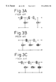
- FIGS. 3A to 3 C show examples of a connection arrangement for a resonator-type SAW filter
- FIG. 4 shows occurrence of a spurious signal in a conventional resonator-type SAW filter
- FIG. 5 shows a principle and a structure of a resonator-type SAW filter according to the present invention
- FIG. 6 is a top view showing an overall arrangement of an SPSSP-style resonator-type SAW filter common to every embodiment of the present invention
- FIG. 7 shows the pass characteristic in the first embodiment
- FIGS. 8A to 8 C show the pass characteristic at and around a frequency causing a spurious signal in the second embodiment
- FIGS. 9A to 9 C schematically show a general change in the pass characteristic resulting from a variation of a pitch between adjoining electrodes
- FIGS. 10A to 10 C schematically show a change in frequency causing a spurious signal which results from a variation of a pitch between adjoining electrodes.
- FIGS. 1A to 1 C show a basic structure of a SAW resonator.
- FIG. 1A is an oblique view showing a SAW resonator element schematically.
- FIG. 1B shows an electrode pattern.
- FIG. 1C shows a symbol for a SAW resonator.
- a standard SAW resonator element has a pair of reflectors 1 and 3 , each having a plurality of reflector electrodes arranged in the form of a grid on a substrate 100 made of a piezoelectric material.
- An IDT 2 having numerous pairs of screen-like electrodes is interposed between the reflectors 1 and 3 . Resonance resulting from reciprocation of a surface acoustic wave between the reflectors 1 and 3 is fed to an electric circuit via input/output terminals 11 and 12 .
- the pitch between adjoining reflector electrodes, which is referred to as an inter-electrode pitch, in the reflectors 1 and 3 shall be defined as ⁇ REF
- the pitch between adjoining interdigital electrodes, which is referred to as an inter-electrode pitch, in the IDT 2 shall be defined as ⁇ IDt .
- the values of the inter-electrode pitches are determined according to a resonant frequency. In the prior art SAW resonator element, ⁇ REF and ⁇ IDT have an equal value.
- the foregoing SAW resonator element is usually expressed with a symbol shown in FIG. 1 C.
- FIGS. 2A and 2B show examples of electrode patterns for a conventional SAW filter.
- FIG. 2A shows a transversal electrode pattern.
- FIG. 2B shows a cascaded electrode pattern.
- References 1 and 3 on both sides of FIG. 2A or 2 B denote reflectors.
- An IDT is located in the center.
- grounded electrodes are arranged alternately. For the sake of illustration, the number of electrodes is not so large. In reality, quite a large number of electrodes are arranged on the substrate.
- a SAW resonator with a pair of terminals includes an equivalent circuit electrically equivalent to a crystal oscillator.
- a resonator-type filter can be realized by connecting SAW resonators in series and parallel with one another in the form of a multistage structure.
- FIGS. 3A to 3 C show examples of connection arrangements for SAW resonators having a pair of terminals in a resonator-type SAW filter.
- Reference S denotes a SAW resonator having a pair of terminals and being connected in series with the other.
- Reference P denotes a SAW resonator having a pair of terminals and being connected in parallel with the other.
- FIG. 3A shows an SPSSP arrangement.
- FIG. 3B shows a PSPSP arrangement.
- FIG. 3C shows an SPSPSP arrangement.
- the resonator-type filter is available in various modes dependent on connection arrangements.
- a spike or what is referred to as a spurious peak occurs at a certain frequency outside a passband because of the structure of the filter.
- the spurious peak causes the stop-band suppressibility to drop or the attenuation ratio to rise like a spike.
- FIG. 4 shows occurrence of a spurious peak caused by a conventional resonator-type SAW filter.
- the spike in FIG. 4 is a spurious peak.
- an attenuation ratio does not decrease very much at the frequency of the spurious peak.
- the suppressibility deteriorates by a degree corresponding to the height of the spurious peak.
- FIG. 5 is a diagram showing a principle and a structure of a resonator-type SAW filter according to the present invention.
- a plurality of SAW resonators each having a pair of terminals as well as reflectors 1 and 3 and an IDT 2 , are connected in series and parallel with one another.
- an inter-electrode pitch ⁇ SREF in the reflectors 1 and 3 has a different value from an inter-electrode pitch ⁇ SIDT in the IDTs 2 .
- the resonator-type SAW filter is available in various connection arrangements.
- the present invention can apply to all of the arrangements. Embodiments in which the present invention is applied to the SPSSP arrangement shown in FIG. 3A will be described.
- FIG. 6 is a top view of a resonator-type SAW filter of the embodiment of the present invention.
- reference 100 denotes a piezoelectric substrate on which elements to be described below are mounted; 11 denotes an input pad; 12 denotes an output pad; 13 and 14 denote ground pads; and S 1 , S 2 , and S 3 denote SAW resonators each having a pair of terminals connected in series with one another; P 1 and P 2 denote SAW resonators each having a pair of terminals and being connected in parallel with the other.
- the substrate 100 is a 36° Y-X lithium tantalate (LiTaO 3 ) substrate in which a surface acoustic wave signal propagates in X direction.
- the electrodes are made of sputtered aluminum film.
- Each SAW resonator having a pair of terminals comprises two reflectors and an IDT interposed between the reflectors.
- the first SAW resonator S 1 having a pair of terminals and being connected in series with the other is composed of reflectors 1 -S 1 and 3 -S 1 located on both sides and an IDT 2 -S 1 located in the center.
- the electrode patterns of the reflectors and IDT are, for example, as shown in FIG. 5 .
- the first embodiment is a resonator-type SAW filter that is a band-pass filter whose passband ranges from 850 to 900 MHz.
- an inter-electrode pitch ⁇ SREF in reflectors in SAW resonators each having a pair of terminals and being connected in series with the other an inter-electrode pitch ⁇ SIDT in IDTs therein, an inter-electrode pitch ⁇ l PREF in reflectors in SAW resonators each having a pair of terminals and being connected in parallel with the other, and an inter-electrode pitch ⁇ PIDT in IDTs therein are set to 4.42 micrometers.
- the pass characteristic of the conventional resonator-type SAW filter is plotted as a graph shown in FIG. 4 .
- the inter-electrode pitch ⁇ SREF in the reflectors in the three SAW resonators, each having a pair of terminals and being connected in series with the other is set to 4.38 micrometers.
- FIG. 7 shows the passing characteristic of the resonator-type SAW filter of this embodiment.
- the characteristic graph of the resonator-type SAW filter of this embodiment shows the same curves at the frequencies in a passband and the suppressed frequencies as those the characteristic graph of the conventional filter does, but does not include a sharply rising spurious peak which is seen in the characteristic of the conventional filter.
- the absolute attenuation ratio at the frequency of the spurious peak is about 39 dB which is about 7 dB more than that of the conventional filter.
- the inter-electrode pitch ⁇ PREF in the reflectors in two SAW resonators each having a pair of terminals and being connected in parallel with the other, and the inter-electrode pitch ⁇ PIDT in IDTs therein are set to 4.60 micrometers.
- the inter-electrode pitch ⁇ SIDT in IDTs in SAW resonators each having a pair of terminals and being connected in series with the other is set to 4.42 micrometers, and the inter-electrode pitch ⁇ SREF in reflectors therein is set to gradually-decreasing values; 4.40, 4.39, and 4.38 micrometers.
- FIGS. 8A to 8 C show a change in the spurious peak resulting from the gradual decrease in ⁇ SREF value.
- FIG. 8A shows a spurious peak occurring when the ⁇ SREF value is 4.40 micrometers.
- FIG. 8B shows a spurious peak occurring when the ⁇ SREF value is 4.39 micrometers.
- FIG. 8C shows a spurious peak occurring when the ⁇ SREF value is 4.38 micrometers.
- FIGS. 8A to 8 C are enlarged views of part of FIG. 7 corresponding to a limited frequency range, thus showing the change in the spurious peak more accurately.
- FIGS. 9A to 9 C schematically show a general change in the pass characteristic of a resonator-type SAW filter in which the inter-electrode pitch ⁇ SREF in reflectors in SAW resonators each having a pair of terminals and being connected in series with the other is varied relative to the inter-electrode pitch ⁇ SIDT in IDTs therein.
- FIG. 9A shows the pass characteristic of a conventional resonator-type SAW filter in which the ⁇ SREF value is equal to the ⁇ SIDT value.
- FIG. 9A shows occurrence of a sharp spurious peak at a frequency higher than the passband. The suppressibility of this frequency is as low as a level indicated at a.
- FIG. 9B shows the passing characteristic of a resonator-type SAW filter of the present invention in which the ⁇ SREF value is different from the ⁇ SIDT value. Unlike FIG. 9A, FIG. 9B does not show occurrence of a sharp spurious peak. When the ⁇ SREF value is larger or smaller than the ⁇ SIDT value, the signal height of a spurious signal is reduced. Thus, when the ⁇ SREF value is different from the ⁇ SIDT value, the attenuation ratio for the frequency band increases to provide high extra-passband suppressibility.
- FIG. 9C shows the passing characteristic of the resonator-type SAW filter under the above conditions. As seen from FIG. 9C, a spurious signal does not occur. The suppression characteristic for the frequency is smoother than that in FIG. 9 B. Nevertheless, the overall suppressibility is almost the same as that in FIG. 9 B.
- FIGS. 10A to 10 C schematically show the change.
- the ⁇ SREF value is smaller than the ⁇ SIDT value.
- the ⁇ SREF value is equal to the ⁇ SIDT value.
- the ⁇ SREF value is larger than the ⁇ SIDT value.
- the graphs are plotted to indicate occurrence of a spurious signal even when the ⁇ A SREF value differs from the ⁇ SIDT value.
- the frequency becomes higher when the ⁇ SREF value is smaller than the ⁇ SIDT value.
- the frequency becomes lower when the ⁇ SREF value is larger than the ⁇ SIDT value. Occurrence of a spurious signal at a frequency to be suppressed can therefore be prevented by specifying an appropriate value as the ⁇ SREF value relative to the ⁇ SIDT value.
- a range in which the ⁇ SREF value can be varied relative to the ⁇ SIDT value without greatly affecting other frequency characteristics except the characteristic concerning occurrence of a spurious signal is a range satisfying such a condition as 0.98 ⁇ SIDT ⁇ SREF ⁇ SIDT , wherein the ⁇ SREF value is smaller than the ⁇ SIDT value.
- the range meets such a condition as ⁇ SIDT ⁇ SREF ⁇ 1.04 ⁇ SIDT .
- the stop-band suppressibility can be markedly improved by reducing the signal height of a spurious signal. Moreover, a frequency causing a spurious signal can be changed arbitrarily to some extent. It is therefore possible to provide high stop-band suppressibility at a frequency inherent to equipment employed.
- the improvement of stop-band suppressibility according to the present invention hardly affects the conventional pass characteristic. Conventional technologies including a design technology can therefore be utilized as they are.
- a resonator-type SAW filter according to the present invention can be materialized with little effort.
Landscapes
- Physics & Mathematics (AREA)
- Acoustics & Sound (AREA)
- Surface Acoustic Wave Elements And Circuit Networks Thereof (AREA)
Abstract
An object of the present invention is to realize a resonator-type SAW filter permitting higher extra-passband suppressibility by minimizing occurrence of an unwanted spurious peak. A resonator-type SAW filter in which a plurality of SAW resonators each having reflectors and an interdigital transducer and being connected in series and parallel with the other, wherein in at least one of the SAW resonators, particularly in at least one of the SAW resonators connected in series with one another, an inter-electrode pitch λREF in the reflectors has a different value from an inter-electrode pitch λIDT in the interdigital transducers.
Description
This application is a continuation, of application Ser. No. 08/214,311, filed Mar. 17, 1994, now abandoned.
(1) Field of the Invention
The present invention relates to a band-pass resonator-type surface-acoustic-wave filter having a plurality of surface-acoustic-wave resonators connected in series and parallel with one another. More particularly, this invention is concerned with a resonator-type surface-acoustic-wave filter for reducing the signal height of a spurious peak that causes the extra-passband suppressibility to deteriorate and occurs especially at a frequency outside a passband.
(2) Description of the Related Art
A known high-frequency band pass filter includes a surface-acoustic-wave (SAW) resonator in which different electrode patterns are formed in reflectors and an InterDigital Transducer (IDT) on a piezoelectric element. With the recent popularity of mobile telephones and portable telephones, there is an increasing demand for SAW resonators as small, thin radio-frequency (RF) filters.
Generally, the SAW resonator element has a pair of reflectors each of which has a plurality of reflector electrodes arranged in the form of a grid on a substrate made of a piezoelectric material or a magnetostrictive material. An IDT having numerous pairs of screen-like electrodes is interposed between the two reflectors. Resonance resulting from reciprocation of a surface acoustic wave between the two reflectors is fed to an electric circuit via input/output terminals. The pitch between adjoining reflector electrodes, which is referred to as an inter-electrode pitch, in the reflectors shall be defined as λREF, and the pitch between adjoining interdigital electrodes in the IDT, which is referred to as an inter-electrode pitch, shall be defined as λIDT. The values of the inter-electrode pitches are determined according to a resonant frequency. In the prior art SAW resonator element, λREF and λIDT have an equal value.
A SAW filter that has been adopted widely to date has a transversal structure or what is referred to as a cascade structure in which transversal structures are cascaded in two stages. For example, Japanese Unexamined Patent Publication (Kokai) No.57-99813 has disclosed a transversal SAW filter, and Japanese Unexamined Patent Publication (Kokai) No.4-94208 has disclosed a cascaded SAW filter. In each of SAW filters shown in these documents, reflectors are arranged in both sides of an IDT.
A SAW resonator with a pair of terminals includes an equivalent circuit electrically equivalent to a crystal oscillator. As already known, a resonator-type filter can be realized by connecting the SAW resonators in series and parallel with one another in the form of a multistage structure. Therefore, the resonator-type filter is available in various modes dependent on connection arrangements. In a resonator-type filter based on SAW resonators, each SAW resonator having a pair of terminals is treated as a pure reactance element in order to utilize a resonant effect. Impedance occurring at any of frequencies in a passband can therefore be limited. This obviates the necessity of an external matching circuit and realizes a reduced insertion loss. The resonator-type filter acts as a narrow-band band pass filter because of the generally large capacity ratio among resonators. Owing to characteristics similar to those of a narrow-band band-pass filter, the resonator-type filter is used as an RF filter for a mobile telephone or a portable telephone.
Thus, the SAW resonator having a pair of terminals and the resonator-type filter based on the SAW resonators differ from each other even in terms of the design technology. The present invention relates to a resonator-type filter composed of SAW resonators each having a pair of terminals. Hereafter, the resonator-type filter composed of SAW resonators each having a pair of terminals is referred to as a resonator-type SAW filter.
The resonator-type SAW filter offers great freedom in specifying constants for an individual resonator in the process of design or in selecting a combination of resonators to be connected in series or parallel with one another. This leads to a low loss and a relatively large stop-band attenuation ratio. Thanks to these advantages, resonator-type SAW filters are taking the place of conventional filters.
One of the important characteristics of a band pass filter is stop-band suppressibility. The stop-band suppressibility indicates to what extent signals with frequencies outside a passband can be blocked relative to signals with frequencies within the passband. When a band pass filter is employed as an RF filter for radio communications, if the stop-band suppressibility is small, interference and other problems may occur. Therefore, a large stop-band suppressibility is usually desired.
In a conventional resonator-type SAW filter, a spike or what is referred to as a spurious peak occurs at a certain frequency outside a passband because of the structure of the filter. The spurious peak causes the stop-band suppressibility to drop or the attenuation ratio to rise like a spike. In equipment using the resonator-type SAW filter, when the frequency causing the spurious peak corresponds to a frequency that must be suppressed, the suppressibility deteriorates by a degree corresponding to the height of the spurious peak.
When a resonator-type SAW filter is needed, a resonator-type SAW filter permitting high suppressibility at all stop-band frequencies should be adopted on the assumption that stop-band suppressibility may deteriorate due to the spurious peak. In this case, occurrence of a spurious peak would pose no problem. Alternatively, a spurious peak is reduced in signal height by adjusting the combination of or the number of stages of SAW resonators each having a pair of terminals to be connected in series or parallel with one another. However, it is very hard to manufacture a resonator-type SAW filter permitting high suppressibility at all stop-band frequencies. Adjusting the combination of or the number of stages of SAW resonators each having a pair of terminals requires considerable labor and is quite time-consuming.
The present invention attempts to solve the aforesaid problems. An object of the present invention is to realized a resonator-type SAW filter permitting higher extra-passband suppressibility by minimizing the occurrence of an unwanted spurious peak.
In a resonator-type SAW filter according to the present invention, a plurality of SAW resonators each having a pair of terminals as well as reflectors and an IDT are connected in series and parallel with one another. In at least one of the SAW resonators, particularly in at least one of the SAW resonators having a pair of terminals and being connected in series with another, an inter-electrode pitch λREF in the reflectors has a different value than inter-electrode pitch λIDT in the IDTs.
In a resonator-type SAW filter in the second mode of the present invention, only in SAW resonators each having a pair of terminals and being connected in series with the other, is the inter-electrode pitch λSREF in the reflectors a different value to the inter-electrode pitch λSIDT in the IDT.
Further, in a resonator-type SAW filter in the third mode of the present invention, in all SAW resonators, the inter-electrode pitch λREF in the reflectors is different value to the inter-electrode pitch λIDT in the IDTs.
For a conventional resonator-type SAW filter, the inter-electrode pitch in the reflectors in each SAW resonator having a pair of terminals is set to the same value as the inter-electrode pitch in the IDT therein. In contrast, for a resonator-type SAW filter of the present invention, in at least one of SAW resonators, particularly, in at least one of SAW resonators each having a pair of terminals and being connected in series with the other, the inter-electrode pitch λREF in the reflectors is set to a slightly different value from the inter-electrode pitch λIDT in the IDTs. It has been found that this structure can reduce the height of a spurious peak. Moreover, as far as the difference is the smallest possible value which can reduce the height of a spurious peak, the difference hardly affects other characteristics including the intra-passband characteristic. A conventional design procedure can therefore be used.
In SAW resonators each having a pair of terminals and being connected in parallel with the other, when the inter-electrode pitch in the reflectors is set to a value different from the inter-electrode pitch in the IDTs, it becomes hard to provide the desired frequency characteristics. Only in SAW resonators each having a pair of terminals and being connected in series with the other, therefore, the inter-electrode pitches are set to different values. Under certain conditions, however, even if the inter-electrode pitches are set to different values in SAW resonators each having a pair of terminals and being connected in parallel with the other, the height of a spurious peak could be reduced without affecting other frequency characteristics.
The aforesaid Japanese Unexamined Patent Publication (Kokai) No.57-99813 has disclosed a transversal SAW filter in which an inter-electrode pitch in reflectors is made slightly shorter than an inter-electrode pitch in IDTs in an effort to optimize both sharpness of resonance and resonant resistance. However, this document discloses the SAW filter consisting of only one SAW resonator, but does not disclose the SAW filter consisting of a plurality of SAW resonators. Therefore, the SAW filter disclosed in the Japanese Unexamined Patent Publication (Kokai) No.57-99813 differs from the resonator-type SAW filter of the present invention even in terms of the design technology. In the resonator-type SAW filter, since the resonant resistance is sufficiently low, measures need not be taken to optimize both the sharpness of resonance and resonant resistance.
The present invention will be more clearly understood from the description as set forth below with reference to the accompanying drawings, wherein:
FIGS. 1A to 1C show a basic structure of a SAW resonator;
FIGS. 2A and 2B respectively show the structures of two types of conventional SAW resonators;
FIGS. 3A to 3C show examples of a connection arrangement for a resonator-type SAW filter;
FIG. 4 shows occurrence of a spurious signal in a conventional resonator-type SAW filter;
FIG. 5 shows a principle and a structure of a resonator-type SAW filter according to the present invention;
FIG. 6 is a top view showing an overall arrangement of an SPSSP-style resonator-type SAW filter common to every embodiment of the present invention;
FIG. 7 shows the pass characteristic in the first embodiment;
FIGS. 8A to 8C show the pass characteristic at and around a frequency causing a spurious signal in the second embodiment;
FIGS. 9A to 9C schematically show a general change in the pass characteristic resulting from a variation of a pitch between adjoining electrodes;
FIGS. 10A to 10C schematically show a change in frequency causing a spurious signal which results from a variation of a pitch between adjoining electrodes.
Before proceeding to a detailed description of the preferred embodiments of the present invention, a prior art resonator-type SAW filter and its problems will be described, with reference to the accompanying drawings relating thereto, for a clearer understanding of the differences between the prior art and the present invention.
FIGS. 1A to 1C show a basic structure of a SAW resonator. FIG. 1A is an oblique view showing a SAW resonator element schematically. FIG. 1B shows an electrode pattern. FIG. 1C shows a symbol for a SAW resonator.
As shown in FIGS. 1A and 1B, a standard SAW resonator element has a pair of reflectors 1 and 3, each having a plurality of reflector electrodes arranged in the form of a grid on a substrate 100 made of a piezoelectric material. An IDT 2 having numerous pairs of screen-like electrodes is interposed between the reflectors 1 and 3. Resonance resulting from reciprocation of a surface acoustic wave between the reflectors 1 and 3 is fed to an electric circuit via input/ output terminals 11 and 12. The pitch between adjoining reflector electrodes, which is referred to as an inter-electrode pitch, in the reflectors 1 and 3 shall be defined as λREF, and the pitch between adjoining interdigital electrodes, which is referred to as an inter-electrode pitch, in the IDT 2 shall be defined as λIDt. The values of the inter-electrode pitches are determined according to a resonant frequency. In the prior art SAW resonator element, λREF and λIDT have an equal value.
The foregoing SAW resonator element is usually expressed with a symbol shown in FIG. 1C.
A SAW filter that has been adopted widely to date has a transversal structure or what is referred to as a cascade structure in which transversal structures are cascaded in two stages. FIGS. 2A and 2B show examples of electrode patterns for a conventional SAW filter. FIG. 2A shows a transversal electrode pattern. FIG. 2B shows a cascaded electrode pattern. References 1 and 3 on both sides of FIG. 2A or 2B denote reflectors. An IDT is located in the center. As illustrated, grounded electrodes are arranged alternately. For the sake of illustration, the number of electrodes is not so large. In reality, quite a large number of electrodes are arranged on the substrate.
A SAW resonator with a pair of terminals includes an equivalent circuit electrically equivalent to a crystal oscillator. As already known, a resonator-type filter can be realized by connecting SAW resonators in series and parallel with one another in the form of a multistage structure. FIGS. 3A to 3C show examples of connection arrangements for SAW resonators having a pair of terminals in a resonator-type SAW filter. Reference S denotes a SAW resonator having a pair of terminals and being connected in series with the other. Reference P denotes a SAW resonator having a pair of terminals and being connected in parallel with the other. FIG. 3A shows an SPSSP arrangement. FIG. 3B shows a PSPSP arrangement. FIG. 3C shows an SPSPSP arrangement. Thus, the resonator-type filter is available in various modes dependent on connection arrangements.
As previously described, in a conventional resonator-type SAW filter, a spike or what is referred to as a spurious peak occurs at a certain frequency outside a passband because of the structure of the filter. The spurious peak causes the stop-band suppressibility to drop or the attenuation ratio to rise like a spike. FIG. 4 shows occurrence of a spurious peak caused by a conventional resonator-type SAW filter. The spike in FIG. 4 is a spurious peak. As illustrated, an attenuation ratio does not decrease very much at the frequency of the spurious peak. In equipment using the resonator-type SAW filter, when the frequency of the spurious peak corresponds to a frequency that must be suppressed, the suppressibility deteriorates by a degree corresponding to the height of the spurious peak.
FIG. 5 is a diagram showing a principle and a structure of a resonator-type SAW filter according to the present invention. As shown in FIG. 5, in a resonator-type SAW filter according to the present invention, a plurality of SAW resonators, each having a pair of terminals as well as reflectors 1 and 3 and an IDT 2, are connected in series and parallel with one another. In at least one of the SAW resonators each having a pair of terminals and being connected in series with the other, an inter-electrode pitch λSREF in the reflectors 1 and 3 has a different value from an inter-electrode pitch λSIDT in the IDTs 2.
As shown in FIGS. 3A to 3C, the resonator-type SAW filter is available in various connection arrangements. The present invention can apply to all of the arrangements. Embodiments in which the present invention is applied to the SPSSP arrangement shown in FIG. 3A will be described.
FIG. 6 is a top view of a resonator-type SAW filter of the embodiment of the present invention.
In FIG. 6, reference 100 denotes a piezoelectric substrate on which elements to be described below are mounted; 11 denotes an input pad; 12 denotes an output pad; 13 and 14 denote ground pads; and S1, S2, and S3 denote SAW resonators each having a pair of terminals connected in series with one another; P1 and P2 denote SAW resonators each having a pair of terminals and being connected in parallel with the other. In this embodiment, the substrate 100 is a 36° Y-X lithium tantalate (LiTaO3) substrate in which a surface acoustic wave signal propagates in X direction. The electrodes are made of sputtered aluminum film. This arrangement produces an SPSSP resonator-type SAW filter shown in FIG. 3A. Each SAW resonator having a pair of terminals comprises two reflectors and an IDT interposed between the reflectors. For example, the first SAW resonator S1 having a pair of terminals and being connected in series with the other is composed of reflectors 1-S1 and 3-S1 located on both sides and an IDT 2-S1 located in the center. The electrode patterns of the reflectors and IDT are, for example, as shown in FIG. 5.
The first embodiment is a resonator-type SAW filter that is a band-pass filter whose passband ranges from 850 to 900 MHz. In a conventional resonator-type SAW filter, an inter-electrode pitch λSREF in reflectors in SAW resonators each having a pair of terminals and being connected in series with the other, an inter-electrode pitch λSIDT in IDTs therein, an inter-electrode pitch λl PREF in reflectors in SAW resonators each having a pair of terminals and being connected in parallel with the other, and an inter-electrode pitch λPIDT in IDTs therein are set to 4.42 micrometers. The pass characteristic of the conventional resonator-type SAW filter is plotted as a graph shown in FIG. 4. In contrast, in the resonator-type SAW filter of this embodiment, only the inter-electrode pitch λSREF in the reflectors in the three SAW resonators, each having a pair of terminals and being connected in series with the other, is set to 4.38 micrometers. FIG. 7 shows the passing characteristic of the resonator-type SAW filter of this embodiment.
As apparent from comparison between FIGS. 7 and 4, the characteristic graph of the resonator-type SAW filter of this embodiment shows the same curves at the frequencies in a passband and the suppressed frequencies as those the characteristic graph of the conventional filter does, but does not include a sharply rising spurious peak which is seen in the characteristic of the conventional filter. The absolute attenuation ratio at the frequency of the spurious peak is about 39 dB which is about 7 dB more than that of the conventional filter.
According to the second embodiment, in the SPSSP-style resonator-type resonator shown in FIG. 6, the inter-electrode pitch λPREF in the reflectors in two SAW resonators each having a pair of terminals and being connected in parallel with the other, and the inter-electrode pitch λPIDT in IDTs therein are set to 4.60 micrometers. The inter-electrode pitch λSIDT in IDTs in SAW resonators each having a pair of terminals and being connected in series with the other is set to 4.42 micrometers, and the inter-electrode pitch λSREF in reflectors therein is set to gradually-decreasing values; 4.40, 4.39, and 4.38 micrometers. FIGS. 8A to 8C show a change in the spurious peak resulting from the gradual decrease in λSREF value. FIG. 8A shows a spurious peak occurring when the λSREF value is 4.40 micrometers. FIG. 8B shows a spurious peak occurring when the λSREF value is 4.39 micrometers. FIG. 8C shows a spurious peak occurring when the λSREF value is 4.38 micrometers. FIGS. 8A to 8C are enlarged views of part of FIG. 7 corresponding to a limited frequency range, thus showing the change in the spurious peak more accurately.
As apparent from FIGS. 8A to 8C, the larger the difference between the inter-electrode pitch λSIDT in IDTs in SAW resonators each having a pair of terminals and being connected in series with the other and the inter-electrode pitch λSREF in reflectors therein is, the more successfully the signal height of a spurious peak is reduced.
The first and second embodiments have been described so far. Next, mention will be made of a change in the pass characteristic of a resonator-type SAW filter in which an inter-electrode pitch in IDTs in SAW resonators is set to a different value from an inter-electrode pitch in reflectors therein. The change in pass characteristic has been revealed by another experimental study.
FIGS. 9A to 9C schematically show a general change in the pass characteristic of a resonator-type SAW filter in which the inter-electrode pitch λSREF in reflectors in SAW resonators each having a pair of terminals and being connected in series with the other is varied relative to the inter-electrode pitch λSIDT in IDTs therein. FIG. 9A shows the pass characteristic of a conventional resonator-type SAW filter in which the λSREF value is equal to the λSIDT value. FIG. 9A shows occurrence of a sharp spurious peak at a frequency higher than the passband. The suppressibility of this frequency is as low as a level indicated at a.
This means that satisfactory suppression is not attained at a frequency outside the passband. In the conventional resonator-type SAW filter, therefore, the number of or the combination of SAW resonators to be connected in series and parallel with one another is increased or modified on the assumption that the spurious peak may occur. Thus, the extra-passband suppressibility is improved.
FIG. 9B shows the passing characteristic of a resonator-type SAW filter of the present invention in which the λSREF value is different from the λSIDT value. Unlike FIG. 9A, FIG. 9B does not show occurrence of a sharp spurious peak. When the λSREF value is larger or smaller than the λSIDT value, the signal height of a spurious signal is reduced. Thus, when the λSREF value is different from the λSIDT value, the attenuation ratio for the frequency band increases to provide high extra-passband suppressibility.
As described previously, when the inter-electrode pitch λPREF in the reflectors 1 and 3 in SAW resonators each having a pair of terminals and being connected in parallel with the other is set to a different value from the inter-electrode pitch λPIDT in the IDTs 2 therein, it becomes almost impossible to provide the desired frequency characteristics. In general, it is more practical to make the λSREF value different from the λSIDT value in SAW resonators connected in series with one another. Even when the λPREF value is different from the λPIDT value in SAW resonators connected in parallel with one another, if given conditions are satisfied, occurrence of a spurious signal is found to be minimized without greatly affecting other frequency characteristics. The conditions are such that the λSREF value is larger than the λSIDT value in all SAW resonators connected in series with one another, the λPREF value is smaller than the λPIDT value in all SAW resonators connected in parallel with one another, and the λSREF value is equal to the λPREF value. FIG. 9C shows the passing characteristic of the resonator-type SAW filter under the above conditions. As seen from FIG. 9C, a spurious signal does not occur. The suppression characteristic for the frequency is smoother than that in FIG. 9B. Nevertheless, the overall suppressibility is almost the same as that in FIG. 9B.
Next, mention will be made of a change in frequency causing a spurious signal which occurs when the inter-electrode pitch λSREF in reflectors in SAW resonators each having a pair of terminals and being connected in series with the other is varied relative to the inter-electrode pitch λSIDT in IDTs therein. FIGS. 10A to 10C schematically show the change. In FIG. 10A, the λSREF value is smaller than the λSIDT value. In FIG. 10B, the λSREF value is equal to the λSIDT value. In FIG. 10C, the λSREF value is larger than the λSIDT value. As described above, when the λSREF value differs from the λSIDT value, the signal height of a spurious signal is reduced. For description's sake, the graphs are plotted to indicate occurrence of a spurious signal even when the λA SREF value differs from the λSIDT value.
Compared with the frequency causing a spurious signal when the λSREF value is, as shown in FIG. 10B, equal to the λSIDT value, the frequency becomes higher when the λSREF value is smaller than the λSIDT value. The frequency becomes lower when the λSREF value is larger than the λSIDT value. Occurrence of a spurious signal at a frequency to be suppressed can therefore be prevented by specifying an appropriate value as the λSREF value relative to the λSIDT value.
A range in which the λSREF value can be varied relative to the λSIDT value without greatly affecting other frequency characteristics except the characteristic concerning occurrence of a spurious signal, is a range satisfying such a condition as 0.98×λSIDT<λSREF<λSIDT, wherein the λSREF value is smaller than the λSIDT value. When the λSREF value is larger than the λSIDT value, the range meets such a condition as λSIDT<λSREF<1.04×λSIDT.
As described so far, according to the present invention, the stop-band suppressibility can be markedly improved by reducing the signal height of a spurious signal. Moreover, a frequency causing a spurious signal can be changed arbitrarily to some extent. It is therefore possible to provide high stop-band suppressibility at a frequency inherent to equipment employed. The improvement of stop-band suppressibility according to the present invention hardly affects the conventional pass characteristic. Conventional technologies including a design technology can therefore be utilized as they are. A resonator-type SAW filter according to the present invention can be materialized with little effort.
Claims (6)
1. A resonator-type surface-acoustic wave (SAW) filter comprising:
a plurality of SAW resonators connected in series and parallel with each other, each SAW resonator has a pair of terminals as well as reflectors having electrodes and an interdigital transducer having interdigital electrodes, wherein:
in at least one of said SAW resonators connected in series with another of said SAW resonators, a pitch between adjoining electrodes, which is referred to as an inter-electrode pitch λSREF in said reflectors is different from a pitch between adjoining interdigital electrodes, which is referred to as an inter-electrode pitch λSIDT in said interdigital transducers; and
in each of said SAW resonators connected in parallel, a pitch between adjoining electrodes in said reflectors is the same as a pitch between adjoining interdigital electrodes in said interdigital transducers.
2. A resonator-type SAW filter according to claim 1, wherein in said SAW resonators in which said λSREF and said λSIDT are different, said λSREF is larger than said λSIDT.
3. A resonator-type SAW filter according to claim 1, wherein in said SAW resonators in which said λSREF and said λSIDT are different, said λSREF is shorter than said λSIDT.
4. A resonator-type SAW filter according to claim 3, wherein said λSREF and said λSIDT have a relationship as follows:
0.98*λSIDT<λSREF<λSIDT.
5. A resonator-type SAW filter according to claim 3, wherein said λSREF and said λSIDT have a relationship as follows:
λSIDT<λSREF<1.04*λSIDT.
6. A resonator-type surface-acoustic-wave (SAW) filter comprising:
a plurality of SAW resonators connected in series and parallel with each other, each SAW resonator has a pair of terminals as well as reflectors having electrodes and an interdigital transducer having interdigital electrodes, wherein:
in each of said SAW resonators connected in series, a pitch between adjoining electrodes, which is referred to as an inter-electrode pitch λSREF, in said reflectors is different from a pitch between adjoining interdigital electrodes, which is referred to as an inter-electrode pitch λSIDT, in said interdigital transducers;
in each of said SAW resonators connected in parallel, a pitch between adjoining electrodes, which is referred to as an inter-electrode pitch λPREF, in said reflectors is different from a pitch between adjoining interdigital electrodes, which is referred to as an inter-electrode pitch λPIDT in said interdigital transducers; and
said λSREF, λSIDT, λPREF and λPIDT have a relationship as follows:
λSIDT<λSREF=λPREF<λPIDT.
Priority Applications (1)
| Application Number | Priority Date | Filing Date | Title |
|---|---|---|---|
| US08/598,137 US6255916B1 (en) | 1993-05-27 | 1996-02-07 | Resonator-type surface-acoustic-wave filter for reducing the signal strength of a spurious peak |
Applications Claiming Priority (4)
| Application Number | Priority Date | Filing Date | Title |
|---|---|---|---|
| JP5125775A JPH06338756A (en) | 1993-05-27 | 1993-05-27 | Resonator type surface acoustic wave filter |
| JP5-125775 | 1993-05-27 | ||
| US21431194A | 1994-03-17 | 1994-03-17 | |
| US08/598,137 US6255916B1 (en) | 1993-05-27 | 1996-02-07 | Resonator-type surface-acoustic-wave filter for reducing the signal strength of a spurious peak |
Related Parent Applications (1)
| Application Number | Title | Priority Date | Filing Date |
|---|---|---|---|
| US21431194A Continuation | 1993-05-27 | 1994-03-17 |
Publications (1)
| Publication Number | Publication Date |
|---|---|
| US6255916B1 true US6255916B1 (en) | 2001-07-03 |
Family
ID=14918535
Family Applications (1)
| Application Number | Title | Priority Date | Filing Date |
|---|---|---|---|
| US08/598,137 Expired - Fee Related US6255916B1 (en) | 1993-05-27 | 1996-02-07 | Resonator-type surface-acoustic-wave filter for reducing the signal strength of a spurious peak |
Country Status (4)
| Country | Link |
|---|---|
| US (1) | US6255916B1 (en) |
| JP (1) | JPH06338756A (en) |
| DE (1) | DE4408989C2 (en) |
| FR (1) | FR2705845B1 (en) |
Cited By (14)
| Publication number | Priority date | Publication date | Assignee | Title |
|---|---|---|---|---|
| US6339704B1 (en) * | 1998-03-06 | 2002-01-15 | Kabushiki Kaisha Toshiba | Surface acoustic wave device and communication apparatus |
| US6489861B2 (en) * | 2000-04-28 | 2002-12-03 | Oki Electric Industry Co., Ltd. | Antenna duplexer with divided and grounded transmission line |
| US20030025576A1 (en) * | 2001-07-27 | 2003-02-06 | Yuichi Takamine | Surface acoustic wave filter and communication apparatus |
| US20050046520A1 (en) * | 2002-02-25 | 2005-03-03 | Fujitsu Media Devices Limited | Surface acoustic wave device |
| US20050077982A1 (en) * | 2003-08-29 | 2005-04-14 | Tsukasa Funasaka | Surface acoustic wave element and electronic equipment provided with the element |
| EP1330027A3 (en) * | 2002-01-22 | 2009-01-14 | Murata Manufacturing Co., Ltd. | Surface acoustic wave device and communication device comprising it |
| CN100521528C (en) * | 2003-09-02 | 2009-07-29 | 株式会社村田制作所 | Surface acoustic wave device and method for manufacturing the same |
| US8552820B2 (en) | 2009-11-30 | 2013-10-08 | Taiyo Yuden Co., Ltd. | Filter, duplexer and communication module |
| CN108886351A (en) * | 2016-03-31 | 2018-11-23 | 京瓷株式会社 | Elastic wave device and communication device |
| US10601400B1 (en) | 2017-09-07 | 2020-03-24 | Government Of The United States As Represented By The Secretary Of The Air Force | Frequency tunable RF filters via a wide-band SAW-multiferroic hybrid device |
| US20200358421A1 (en) * | 2019-05-06 | 2020-11-12 | Globalfoundries Singapore Pte. Ltd. | Resonator devices and methods of fabricating resonator devices |
| EP3176948B1 (en) * | 2014-07-30 | 2021-03-17 | Kyocera Corporation | Elastic wave element, filter element, and communication device |
| US20210119650A1 (en) * | 2019-05-01 | 2021-04-22 | Skyworks Solutions, Inc. | Multiplexer with acoustic wave resonators |
| US11070194B2 (en) * | 2018-08-17 | 2021-07-20 | Qorvo Us, Inc. | Ladder-type surface acoustic wave device |
Families Citing this family (12)
| Publication number | Priority date | Publication date | Assignee | Title |
|---|---|---|---|---|
| DE69625734T2 (en) * | 1995-03-15 | 2003-05-22 | Matsushita Electric Industrial Co., Ltd. | Acoustic surface wave filter |
| JP3614234B2 (en) * | 1996-03-14 | 2005-01-26 | 沖電気工業株式会社 | Resonator type surface acoustic wave filter |
| US6137380A (en) * | 1996-08-14 | 2000-10-24 | Murata Manufacturing, Co., Ltd | Surface acoustic wave filter utilizing a particularly placed spurious component of a parallel resonator |
| JP3224202B2 (en) * | 1996-11-28 | 2001-10-29 | 富士通株式会社 | Surface acoustic wave device |
| DE19730710C2 (en) * | 1997-07-17 | 2002-12-05 | Epcos Ag | Surface acoustic wave filter with improved slope |
| JP3576367B2 (en) * | 1998-01-30 | 2004-10-13 | 沖電気工業株式会社 | Surface acoustic wave filter |
| JP3419339B2 (en) * | 1999-03-11 | 2003-06-23 | 株式会社村田製作所 | Surface acoustic wave filters, duplexers, communication equipment |
| US7679474B2 (en) * | 2004-01-09 | 2010-03-16 | Panasonic Corporation | Surface acoustic wave resonator, and surface acoustic wave filter |
| JP2005244669A (en) | 2004-02-26 | 2005-09-08 | Fujitsu Media Device Kk | Surface acoustic wave device |
| JP6013829B2 (en) * | 2012-08-17 | 2016-10-25 | 太陽誘電株式会社 | Elastic wave filter, duplexer and module |
| JP5810113B2 (en) * | 2013-02-19 | 2015-11-11 | スカイワークス・パナソニック フィルターソリューションズ ジャパン株式会社 | Elastic wave resonator and elastic wave filter and antenna duplexer using the same |
| FR3114875B1 (en) * | 2020-10-01 | 2023-01-20 | Frecnsys | RESONATOR DEVICE |
Citations (33)
| Publication number | Priority date | Publication date | Assignee | Title |
|---|---|---|---|---|
| US4166258A (en) | 1974-08-29 | 1979-08-28 | International Business Machines Corporation | Thin-film integrated circuit with tank circuit characteristics and applications to thin-film filters and oscillators |
| JPS5619765A (en) | 1979-07-25 | 1981-02-24 | Ricoh Co Ltd | Ink viscosity detecting and controlling device |
| GB2078042A (en) * | 1980-06-13 | 1981-12-23 | Nippon Telegraph & Telephone | Surface acoustic wave resonator |
| JPS5799813A (en) | 1980-12-13 | 1982-06-21 | Nippon Telegr & Teleph Corp <Ntt> | Surface acoustic wave resonator |
| JPS581850A (en) | 1981-06-25 | 1983-01-07 | Ricoh Co Ltd | Floppy disk driving device |
| JPS61142811A (en) * | 1984-12-17 | 1986-06-30 | Toshiba Corp | Surface acoustic wave resonator |
| JPS6388910A (en) | 1986-10-02 | 1988-04-20 | Toyo Commun Equip Co Ltd | Surface acoustic wave resonator |
| JPS63119310A (en) | 1986-11-07 | 1988-05-24 | Nec Corp | Surface acoustic wave resonator |
| US4760359A (en) | 1986-01-10 | 1988-07-26 | Hitachi, Ltd. | Surface acoustic wave resonator |
| JPS643369A (en) | 1987-06-25 | 1989-01-09 | Honda Motor Co Ltd | Oil feeding structure of power transmission |
| JPS6433969A (en) | 1987-05-12 | 1989-02-03 | Texas Instruments Inc | Manufacture of semiconductor device |
| US4837476A (en) * | 1985-04-27 | 1989-06-06 | Pioneer Electronic Corporation | Surface acoustic wave resonator having transducers and reflectors of different periods |
| JPH01231417A (en) | 1988-03-11 | 1989-09-14 | Kokusai Electric Co Ltd | Surface acoustic wave filter |
| JPH0270416A (en) * | 1988-09-06 | 1990-03-09 | Nissei Plastics Ind Co | Preplunging type injection molding machine |
| JPH02104120A (en) | 1988-10-13 | 1990-04-17 | Fujitsu Ltd | Elastic surface wave resonator |
| JPH02194714A (en) * | 1989-01-24 | 1990-08-01 | Toyo Commun Equip Co Ltd | Leaky saw resonator |
| US4954793A (en) * | 1987-12-25 | 1990-09-04 | Mitsubishi Denki Kabushiki Kaisha | Filter bank |
| JPH033412A (en) | 1989-05-31 | 1991-01-09 | Kinseki Ltd | Piezoelectric vibrator and its manufacture |
| JPH0322702A (en) | 1989-06-20 | 1991-01-31 | Seiko Epson Corp | Electrode structure of saw resonator |
| JPH0322703A (en) | 1989-06-20 | 1991-01-31 | Seiko Epson Corp | Saw resonator |
| JPH0334614A (en) * | 1990-05-21 | 1991-02-14 | Toshiba Corp | Surface acoustic wave resonator |
| JPH0380709A (en) * | 1989-08-24 | 1991-04-05 | Pioneer Electron Corp | Surface acoustic wave resonator |
| JPH03261210A (en) * | 1990-03-12 | 1991-11-21 | Seiko Epson Corp | Saw resonator |
| JPH0454011A (en) | 1990-06-21 | 1992-02-21 | Murata Mfg Co Ltd | Longitudinal dual mode surface acoustic wave filter |
| JPH0481823A (en) | 1990-07-25 | 1992-03-16 | Hitachi Ltd | Filter combined with surface acoustic wave resonator |
| JPH0494208A (en) | 1990-08-09 | 1992-03-26 | Kinseki Ltd | Saw resonator filter |
| US5115216A (en) * | 1988-04-11 | 1992-05-19 | Hitachi, Ltd. | Surface acoustic wave filter including saw resonators with transmission spaces therein |
| JPH04207615A (en) * | 1990-11-30 | 1992-07-29 | Toyo Commun Equip Co Ltd | Longitudinal coupling dual mode leaky saw filter |
| JPH04259109A (en) * | 1991-02-13 | 1992-09-14 | Seiko Epson Corp | Two-port saw resonator |
| JPH04275710A (en) | 1991-03-04 | 1992-10-01 | Matsushita Electric Ind Co Ltd | Surface acoustic wave filter |
| EP0530547A1 (en) * | 1991-09-03 | 1993-03-10 | Motorola, Inc. | Acoustic wave device |
| US5204575A (en) * | 1990-10-15 | 1993-04-20 | Kokusai Electric Co., Ltd. | Surface acoustic wave resonator |
| EP0541284A1 (en) | 1991-10-28 | 1993-05-12 | Fujitsu Limited | Surface acoustic wave filter |
-
1993
- 1993-05-27 JP JP5125775A patent/JPH06338756A/en active Pending
-
1994
- 1994-03-16 DE DE4408989A patent/DE4408989C2/en not_active Revoked
- 1994-03-21 FR FR9403269A patent/FR2705845B1/en not_active Expired - Fee Related
-
1996
- 1996-02-07 US US08/598,137 patent/US6255916B1/en not_active Expired - Fee Related
Patent Citations (35)
| Publication number | Priority date | Publication date | Assignee | Title |
|---|---|---|---|---|
| US4166258A (en) | 1974-08-29 | 1979-08-28 | International Business Machines Corporation | Thin-film integrated circuit with tank circuit characteristics and applications to thin-film filters and oscillators |
| JPS5619765A (en) | 1979-07-25 | 1981-02-24 | Ricoh Co Ltd | Ink viscosity detecting and controlling device |
| GB2078042A (en) * | 1980-06-13 | 1981-12-23 | Nippon Telegraph & Telephone | Surface acoustic wave resonator |
| JPS5799813A (en) | 1980-12-13 | 1982-06-21 | Nippon Telegr & Teleph Corp <Ntt> | Surface acoustic wave resonator |
| JPS581850A (en) | 1981-06-25 | 1983-01-07 | Ricoh Co Ltd | Floppy disk driving device |
| JPS61142811A (en) * | 1984-12-17 | 1986-06-30 | Toshiba Corp | Surface acoustic wave resonator |
| EP0186410A2 (en) * | 1984-12-17 | 1986-07-02 | Kabushiki Kaisha Toshiba | Surface acoustic wave resonator |
| US4635009A (en) | 1984-12-17 | 1987-01-06 | Kabushiki Kaisha Toshiba | Surface acoustic wave resonator |
| US4837476A (en) * | 1985-04-27 | 1989-06-06 | Pioneer Electronic Corporation | Surface acoustic wave resonator having transducers and reflectors of different periods |
| US4760359A (en) | 1986-01-10 | 1988-07-26 | Hitachi, Ltd. | Surface acoustic wave resonator |
| JPS6388910A (en) | 1986-10-02 | 1988-04-20 | Toyo Commun Equip Co Ltd | Surface acoustic wave resonator |
| JPS63119310A (en) | 1986-11-07 | 1988-05-24 | Nec Corp | Surface acoustic wave resonator |
| JPS6433969A (en) | 1987-05-12 | 1989-02-03 | Texas Instruments Inc | Manufacture of semiconductor device |
| JPS643369A (en) | 1987-06-25 | 1989-01-09 | Honda Motor Co Ltd | Oil feeding structure of power transmission |
| US4954793A (en) * | 1987-12-25 | 1990-09-04 | Mitsubishi Denki Kabushiki Kaisha | Filter bank |
| JPH01231417A (en) | 1988-03-11 | 1989-09-14 | Kokusai Electric Co Ltd | Surface acoustic wave filter |
| US5115216A (en) * | 1988-04-11 | 1992-05-19 | Hitachi, Ltd. | Surface acoustic wave filter including saw resonators with transmission spaces therein |
| JPH0270416A (en) * | 1988-09-06 | 1990-03-09 | Nissei Plastics Ind Co | Preplunging type injection molding machine |
| JPH02104120A (en) | 1988-10-13 | 1990-04-17 | Fujitsu Ltd | Elastic surface wave resonator |
| JPH02194714A (en) * | 1989-01-24 | 1990-08-01 | Toyo Commun Equip Co Ltd | Leaky saw resonator |
| JPH033412A (en) | 1989-05-31 | 1991-01-09 | Kinseki Ltd | Piezoelectric vibrator and its manufacture |
| JPH0322702A (en) | 1989-06-20 | 1991-01-31 | Seiko Epson Corp | Electrode structure of saw resonator |
| JPH0322703A (en) | 1989-06-20 | 1991-01-31 | Seiko Epson Corp | Saw resonator |
| JPH0380709A (en) * | 1989-08-24 | 1991-04-05 | Pioneer Electron Corp | Surface acoustic wave resonator |
| JPH03261210A (en) * | 1990-03-12 | 1991-11-21 | Seiko Epson Corp | Saw resonator |
| JPH0334614A (en) * | 1990-05-21 | 1991-02-14 | Toshiba Corp | Surface acoustic wave resonator |
| JPH0454011A (en) | 1990-06-21 | 1992-02-21 | Murata Mfg Co Ltd | Longitudinal dual mode surface acoustic wave filter |
| JPH0481823A (en) | 1990-07-25 | 1992-03-16 | Hitachi Ltd | Filter combined with surface acoustic wave resonator |
| JPH0494208A (en) | 1990-08-09 | 1992-03-26 | Kinseki Ltd | Saw resonator filter |
| US5204575A (en) * | 1990-10-15 | 1993-04-20 | Kokusai Electric Co., Ltd. | Surface acoustic wave resonator |
| JPH04207615A (en) * | 1990-11-30 | 1992-07-29 | Toyo Commun Equip Co Ltd | Longitudinal coupling dual mode leaky saw filter |
| JPH04259109A (en) * | 1991-02-13 | 1992-09-14 | Seiko Epson Corp | Two-port saw resonator |
| JPH04275710A (en) | 1991-03-04 | 1992-10-01 | Matsushita Electric Ind Co Ltd | Surface acoustic wave filter |
| EP0530547A1 (en) * | 1991-09-03 | 1993-03-10 | Motorola, Inc. | Acoustic wave device |
| EP0541284A1 (en) | 1991-10-28 | 1993-05-12 | Fujitsu Limited | Surface acoustic wave filter |
Non-Patent Citations (3)
| Title |
|---|
| "Acoustic Surface Wave Resonators for Broadband Applications", J. Vandewege et al., pp. 663-667; Proceedings of the 8th European Microwave Conf; Paris, France; Sep. 8, 1978. |
| "Suppression of Bulk-Scattering Loss in SAW Resonator with Quasi-Constant Acoustic Reflection Periodicity", Yasuo Ebata, Ultrasonics Symposium, (1988), pp. 91-96. |
| Extended New-Type Saw-Resonator-Coupled Filters Used in Duplexer For Japanese Cellular Radio, M. Hikita et al., Electronic Letters, Oct. 22, 1992, vol. 28, No. 22.* |
Cited By (22)
| Publication number | Priority date | Publication date | Assignee | Title |
|---|---|---|---|---|
| US6339704B1 (en) * | 1998-03-06 | 2002-01-15 | Kabushiki Kaisha Toshiba | Surface acoustic wave device and communication apparatus |
| US6489861B2 (en) * | 2000-04-28 | 2002-12-03 | Oki Electric Industry Co., Ltd. | Antenna duplexer with divided and grounded transmission line |
| US20030025576A1 (en) * | 2001-07-27 | 2003-02-06 | Yuichi Takamine | Surface acoustic wave filter and communication apparatus |
| US6816036B2 (en) * | 2001-07-27 | 2004-11-09 | Murata Manufacturing Co. Ltd | Surface acoustic wave filter and communication apparatus |
| EP1330027A3 (en) * | 2002-01-22 | 2009-01-14 | Murata Manufacturing Co., Ltd. | Surface acoustic wave device and communication device comprising it |
| US20050046520A1 (en) * | 2002-02-25 | 2005-03-03 | Fujitsu Media Devices Limited | Surface acoustic wave device |
| US6972644B2 (en) * | 2002-02-25 | 2005-12-06 | Fujitsu Media Devices Limited | Surface acoustic wave ladder filter device having resonators with different electrode pitches and electrostatic capacitances |
| US20050077982A1 (en) * | 2003-08-29 | 2005-04-14 | Tsukasa Funasaka | Surface acoustic wave element and electronic equipment provided with the element |
| US7245193B2 (en) | 2003-08-29 | 2007-07-17 | Seiko Epson Corporation | Surface acoustic wave element and electronic equipment provided with the element |
| CN100521528C (en) * | 2003-09-02 | 2009-07-29 | 株式会社村田制作所 | Surface acoustic wave device and method for manufacturing the same |
| US8552820B2 (en) | 2009-11-30 | 2013-10-08 | Taiyo Yuden Co., Ltd. | Filter, duplexer and communication module |
| EP3176948B1 (en) * | 2014-07-30 | 2021-03-17 | Kyocera Corporation | Elastic wave element, filter element, and communication device |
| CN108886351A (en) * | 2016-03-31 | 2018-11-23 | 京瓷株式会社 | Elastic wave device and communication device |
| US10998880B2 (en) * | 2016-03-31 | 2021-05-04 | Kyocera Corporation | Acoustic wave element and communication apparatus |
| CN108886351B (en) * | 2016-03-31 | 2022-05-27 | 京瓷株式会社 | Elastic wave element and communication device |
| US10601400B1 (en) | 2017-09-07 | 2020-03-24 | Government Of The United States As Represented By The Secretary Of The Air Force | Frequency tunable RF filters via a wide-band SAW-multiferroic hybrid device |
| US11070194B2 (en) * | 2018-08-17 | 2021-07-20 | Qorvo Us, Inc. | Ladder-type surface acoustic wave device |
| US11784633B2 (en) | 2018-08-17 | 2023-10-10 | Qorvo Us, Inc. | Ladder-type surface acoustic wave device |
| US11791799B2 (en) | 2018-08-17 | 2023-10-17 | Qorvo Us, Inc. | Ladder-type surface acoustic wave device |
| US20210119650A1 (en) * | 2019-05-01 | 2021-04-22 | Skyworks Solutions, Inc. | Multiplexer with acoustic wave resonators |
| US20200358421A1 (en) * | 2019-05-06 | 2020-11-12 | Globalfoundries Singapore Pte. Ltd. | Resonator devices and methods of fabricating resonator devices |
| US11811390B2 (en) * | 2019-05-06 | 2023-11-07 | Globalfoundries Singapore Pte. Ltd. | Resonator devices and methods of fabricating resonator devices |
Also Published As
| Publication number | Publication date |
|---|---|
| DE4408989A1 (en) | 1994-12-01 |
| FR2705845B1 (en) | 1996-12-27 |
| FR2705845A1 (en) | 1994-12-02 |
| JPH06338756A (en) | 1994-12-06 |
| DE4408989C2 (en) | 1997-01-16 |
Similar Documents
| Publication | Publication Date | Title |
|---|---|---|
| US6255916B1 (en) | Resonator-type surface-acoustic-wave filter for reducing the signal strength of a spurious peak | |
| US6570470B2 (en) | Surface acoustic wave ladder filter utilizing parallel resonators with different resonant frequencies | |
| US5770985A (en) | Surface acoustic wave filter | |
| US5874868A (en) | Longitudinally coupled surface acoustic wave resonator filter having different distances between transducers | |
| US5694096A (en) | Surface acoustic wave filter | |
| EP0652637B1 (en) | Surface acoustic wave filter | |
| US5831493A (en) | Surface acoustic wave ladder filter utilizing a generated spurious component of the parallel arm | |
| US6034577A (en) | Integrated interdigital electrode saw filter with specified distances between input/output electrodes | |
| EP0664610B1 (en) | Surface acoustic wave filter | |
| US7626475B2 (en) | Saw filter device | |
| US6501208B1 (en) | Compensated surface acoustic wave filter having a longitudinal mode resonator connected with a second resonator | |
| CA2234513C (en) | Surface acoustic wave device | |
| US6518861B2 (en) | Surface acoustic wave filter formed with a ripple at the high frequency shoulder of the pass band | |
| US6326864B1 (en) | Surface acoustic wave filter, duplexer and communications device with specific series resonator multiple anti-resonant point placement | |
| US5589806A (en) | Surface acoustic wave filter having parallel/serial resonator connection based on transmitting and receiving frequencies | |
| US6292071B1 (en) | Surface acoustic wave filter for improving flatness of a pass band and a method of manufacturing thereof | |
| EP1376865B1 (en) | Surface acoustic wave filter, branching filter, and communications apparatus | |
| JPH11312951A (en) | Surface acoustic wave filter | |
| US6720847B2 (en) | Longitudinally-coupled resonator surface acoustic wave filter and communication apparatus using the same | |
| US5699028A (en) | Surface acoustic-wave resonator filter having shifted resonant frequencies | |
| JP3315913B2 (en) | Surface acoustic wave filter | |
| JP2000151355A (en) | Ladder-type saw filter | |
| JP3224455B2 (en) | Surface acoustic wave device | |
| JP2000201053A (en) | Resonator type surface acoustic wave filter |
Legal Events
| Date | Code | Title | Description |
|---|---|---|---|
| REMI | Maintenance fee reminder mailed | ||
| REMI | Maintenance fee reminder mailed | ||
| LAPS | Lapse for failure to pay maintenance fees | ||
| STCH | Information on status: patent discontinuation |
Free format text: PATENT EXPIRED DUE TO NONPAYMENT OF MAINTENANCE FEES UNDER 37 CFR 1.362 |
|
| FP | Lapsed due to failure to pay maintenance fee |
Effective date: 20050703 |