US6206352B1 - Circuit board holding apparatus - Google Patents

Circuit board holding apparatus Download PDF

Info

Publication number
US6206352B1
US6206352B1 US09/202,420 US20242098A US6206352B1 US 6206352 B1 US6206352 B1 US 6206352B1 US 20242098 A US20242098 A US 20242098A US 6206352 B1 US6206352 B1 US 6206352B1
Authority
US
United States
Prior art keywords
circuit board
board
members
movable members
movable
Prior art date
Legal status (The legal status is an assumption and is not a legal conclusion. Google has not performed a legal analysis and makes no representation as to the accuracy of the status listed.)
Expired - Lifetime
Application number
US09/202,420
Inventor
Yasuyuki Ishitani
Makito Seno
Current Assignee (The listed assignees may be inaccurate. Google has not performed a legal analysis and makes no representation or warranty as to the accuracy of the list.)
Panasonic Holdings Corp
Original Assignee
Matsushita Electric Industrial Co Ltd
Priority date (The priority date is an assumption and is not a legal conclusion. Google has not performed a legal analysis and makes no representation as to the accuracy of the date listed.)
Filing date
Publication date
Application filed by Matsushita Electric Industrial Co Ltd filed Critical Matsushita Electric Industrial Co Ltd
Assigned to MATSUSHITA ELECTRIC INDUSTRIAL CO., LTD. reassignment MATSUSHITA ELECTRIC INDUSTRIAL CO., LTD. ASSIGNMENT OF ASSIGNORS INTEREST (SEE DOCUMENT FOR DETAILS). Assignors: ISHITANI, YASUYUKI, SENO, MAKITO
Priority to US09/770,207 priority Critical patent/US6427313B2/en
Application granted granted Critical
Publication of US6206352B1 publication Critical patent/US6206352B1/en
Anticipated expiration legal-status Critical
Expired - Lifetime legal-status Critical Current

Links

Images

Classifications

    • HELECTRICITY
    • H05ELECTRIC TECHNIQUES NOT OTHERWISE PROVIDED FOR
    • H05KPRINTED CIRCUITS; CASINGS OR CONSTRUCTIONAL DETAILS OF ELECTRIC APPARATUS; MANUFACTURE OF ASSEMBLAGES OF ELECTRICAL COMPONENTS
    • H05K13/00Apparatus or processes specially adapted for manufacturing or adjusting assemblages of electric components
    • H05K13/0061Tools for holding the circuit boards during processing; handling transport of printed circuit boards
    • H05K13/0069Holders for printed circuit boards
    • YGENERAL TAGGING OF NEW TECHNOLOGICAL DEVELOPMENTS; GENERAL TAGGING OF CROSS-SECTIONAL TECHNOLOGIES SPANNING OVER SEVERAL SECTIONS OF THE IPC; TECHNICAL SUBJECTS COVERED BY FORMER USPC CROSS-REFERENCE ART COLLECTIONS [XRACs] AND DIGESTS
    • Y10TECHNICAL SUBJECTS COVERED BY FORMER USPC
    • Y10STECHNICAL SUBJECTS COVERED BY FORMER USPC CROSS-REFERENCE ART COLLECTIONS [XRACs] AND DIGESTS
    • Y10S269/00Work holders
    • Y10S269/903Work holder for electrical circuit assemblages or wiring systems
    • YGENERAL TAGGING OF NEW TECHNOLOGICAL DEVELOPMENTS; GENERAL TAGGING OF CROSS-SECTIONAL TECHNOLOGIES SPANNING OVER SEVERAL SECTIONS OF THE IPC; TECHNICAL SUBJECTS COVERED BY FORMER USPC CROSS-REFERENCE ART COLLECTIONS [XRACs] AND DIGESTS
    • Y10TECHNICAL SUBJECTS COVERED BY FORMER USPC
    • Y10TTECHNICAL SUBJECTS COVERED BY FORMER US CLASSIFICATION
    • Y10T29/00Metal working
    • Y10T29/49Method of mechanical manufacture
    • Y10T29/49998Work holding

Definitions

  • the present invention relates to a circuit board holding apparatus which is provided for a component mounting apparatus for mounting, for example, electronic components onto a circuit board such as a printed board and executes holding and releasing the hold of the circuit board, and to a circuit board hold releasing method executed by the circuit board holding apparatus.
  • a portion which executes securing and holding of the printed board in the stage of mounting the electronic components is constructed as follows. That is, as shown in FIGS. 7 and 8, a circuit board holding apparatus 1 for securing and holding a printed board 2 is provided on an X-Y table for moving the printed board 2 in X- and Y-directions. On the circuit board holding apparatus 1 is fixed a pair of stationary members 13 which extend parallel to the X-direction and have an approximately inverted L-like sectional shape.
  • a pair of movable members 14 which extend in the X-direction along inner side surfaces 13 a of the stationary members 13 and oppose each other at both the stationary members 13 and slide in a Z-direction between a board gripping position 20 and a board releasing position 21 while being guided along the inner side surfaces 13 a .
  • the printed board 2 is conveyed into a region between both the stationary members 13 .
  • the X-Y table on which the printed board 2 is secured in this manner is moved into a specified position in the X- and Y-directions, and mounting of electronic components onto the printed board 2 is executed by an electronic component mounting unit 3 .
  • the drive units 15 are operated to move the movable members 14 downward to the board releasing position 21 as shown in FIG. 9, where the gripping of the printed board 2 is released and the printed board 2 is conveyed to the next process.
  • the present invention has been developed to solve the above issue and provide a circuit board holding apparatus which prevents the occurrence of displacement of the mounted electronic components and the state in which the printed board cannot be conveyed to the next process after the electronic components have been mounted onto the circuit board, and a circuit board hold releasing method to be executed by the circuit board holding apparatus.
  • a circuit board holding apparatus for holding a circuit board by gripping a pair of opposed edge portions of a circuit board, comprising:
  • movable members which contact a rear surface of the circuit board and grip each of the edge portions of the circuit board between the movable member and the stationary member in a direction of thickness of the circuit board by moving into a board gripping position, the movable members moving in the direction of thickness of the circuit board between the board gripping position and a board releasing position;
  • a separation mechanism for forcibly separating the circuit board from the stationary members when the movable members move from the board gripping position to the board releasing position for releasing the hold of the circuit board.
  • a circuit board holding apparatus as defined in the first aspect, wherein the separation mechanism is a pressing member which is mounted to the stationary member and puts the circuit board into pressure contact with the movable member.
  • a circuit board holding apparatus as defined in the second aspect, wherein, when the front and rear surfaces of the circuit board are located upward and downward and the movable member moves in a vertical direction, the pressing member is an elastic member having one end-portion to be fixed to the stationary member and the other end portion which is to contact the front surface of the circuit board and presses the circuit board against the movable member.
  • a circuit board holding apparatus as defined in the first aspect, wherein the separation mechanism is a suction unit having a suction section which is arranged on the rear surface side of the circuit board and attracts by suction the rear surface of the circuit board, and a drive unit which moves the suction section in a direction in which the movable member moves together with the moving of the movable member.
  • the separation mechanism is a suction unit having a suction section which is arranged on the rear surface side of the circuit board and attracts by suction the rear surface of the circuit board, and a drive unit which moves the suction section in a direction in which the movable member moves together with the moving of the movable member.
  • a circuit board holding apparatus as defined in the fourth aspect, further comprising a control unit which controls the start of the moving of the movable member from the board gripping position the into the board releasing position, start of the sucking of the circuit board by the suction unit, and the moving of the suction unit by means of the drive unit.
  • a circuit board hold releasing method to be executed by a circuit board holding apparatus which grips a pair of opposed edge portions of a circuit board in a direction of thickness of the circuit board by means of a stationary member and a movable member moving between a board gripping position and a board releasing position, thereby holding the circuit board, comprising:
  • FIG. 1 is a perspective view showing the total construction of a circuit board holding apparatus according to an embodiment of the present invention
  • FIG. 2 is a side view showing a state in which a pressing member shown in FIG. 1 is mounted to a stationary member;
  • FIG. 3 is a side view showing a state in which movable members are arranged in a board gripping position in the circuit board holding apparatus shown in FIG. 1;
  • FIG. 4 is a side view showing a state in which the movable members are arranged in a board releasing position in the circuit board holding apparatus shown in FIG. 1;
  • FIG. 5 is a side view showing a circuit board holding apparatus according to a second embodiment of the present invention in a state in which movable members are arranged in a board gripping position;
  • FIG. 6 is a side view showing a state in which the movable members are arranged in a board releasing position in the circuit board holding apparatus shown in FIG. 5;
  • FIG. 7 is a perspective view showing the overall construction of a prior art circuit board holding apparatus
  • FIG. 8 is a side view showing a state in which movable members are arranged in a board gripping position in the circuit board holding apparatus shown in FIG. 7;
  • FIG. 9 is a side view showing a state in which movable members are arranged in a board releasing position in the circuit board holding apparatus shown in FIG. 7;
  • FIG. 10 is a side view showing a state in which a printed board is stuck to the stationary member side in the circuit board holding apparatus shown in FIG. 7 .
  • circuit board holding apparatus and a circuit board hold releasing method according to an embodiment of the present invention will be described below with reference to the drawings. It is to be noted that the circuit board hold releasing method is executed by the circuit board holding apparatus. Further, identical components are denoted by the same reference numerals in the figures.
  • the pressing member 7 is an example of a separating mechanism in the present invention.
  • the pressing member 7 is an elastic member formed by integrating a fixing section 71 with a contact section 72 which bends toward the printed board 2 side with respect to the fixing section 71 as shown in FIG. 2 .
  • the fixation section 71 has a length slightly greater than a width dimension W of the upper surface 13 c , and as described later, it extends in contact with the upper surface 13 c when the movable member 14 is in the board releasing position 21 .
  • Such a fixing section 71 is mounted to the upper surface 13 c of the stationary member 13 by means of a screw 8 at one end portion 7 a of the pressing member 7 located on the side opposite the contact section 72 . Therefore, the pressing member 7 is fixed to the stationary member 13 .
  • the contact section 72 extends downward by a dimension L beyond the board contact surface 13 b of the stationary member 13 . Therefore, as described later, when the movable member 14 is located near the board gripping position 20 , the other end portion 7 b of the pressing member 7 contacts the front surface 2 b of the printed board 2 arranged on the upper side.
  • the movable members 14 are moved upward by the operation of drive units 15 , and the edge portions 2 a of the printed board 2 are gripped by the board contact surfaces 13 b of the stationary members 13 and the board contact surfaces 14 b of the movable members 14 as shown in FIG. 3 .
  • the pressing member 7 has its one end portion 7 a fixed to the stationary member 13 by means of the screw 8 and has the other end portion 7 b protruded by the dimension L below the board contact surface 13 b . Therefore, the front surface 2 b of the printed board 2 and the other end portion 7 b contact each other just before the edge portion 2 a of the printed board 2 is completely gripped.
  • the fixing section 71 of the pressing member 7 warps upward with the point fixed by the screw 8 serving as a fulcrum. Therefore, in the state in which the printed board 2 is gripped by the stationary member 13 and the movable member 14 , the other end portion 7 b presses the front surface 2 b of the printed board 2 downward, i.e., toward the movable member side by the elastic force of the pressing member 7 .
  • the movable members 14 move downward with the left and right drive units 15 synchronized with each other in operation.
  • the two edge portions 2 a of the printed board 2 are forcibly toward the movable member side by the other end portions 7 b of the pressing members 7 . Therefore, even when the front surface 2 b of the printed board 2 is in the state in which it is stuck to the board contact surfaces 13 b of the stationary members 13 , the stuck state is released by the pressure forces of the pressing members 7 , so that the stationary members 13 and the printed board 2 are separated from each other. Therefore, as shown in FIG.
  • the printed board 2 moves downward together with the movable members 14 in a state in which it is forcibly made to contact the movable members 14 .
  • the state in which the printed board 2 remains stuck to the board contact surfaces 13 b of the stationary members 13 in spite of the fact that the movable member 14 has moved down can be prevented from occurring. Therefore, the phenomenon that the positions of the mounted electronic components are displaced by the subsequent falling of the printed board 2 onto the movable members 14 and the phenomenon that trouble occurs in conveying the printed board 2 to the next process can be prevented from occurring.
  • the aforementioned pressure force of the pressing member 7 can be varied according to the design conditions of the material, thickness, aforementioned dimension L and the like of the pressing member 7 , and it is proper to set the above design conditions to appropriate values according to the adhesion force exerted between the printed board 2 and the stationary member 13 .
  • the pressing members 7 are arranged in the positions corresponding to the four corners of the printed board 2 in the present embodiment as shown in FIG. 1 .
  • the pressing members 7 may be arranged continuously along the edge portion 2 a of the printed board 2 .
  • the pressing member 7 has the L-like leaf spring configuration as illustrated in the present embodiment.
  • the member 7 is not limited to this. That is, the member 7 is only required to be an elastic member having one end portion to be fixed to the stationary member 13 and the other end portion which is to contact the front surface 2 b of the printed board 2 and presses the printed board 2 toward the movable member 14 .
  • the front surface 2 b of the printed board 2 is arranged on the upper side and the rear surface 2 c is arranged on the lower side in the present embodiment.
  • a suction unit 12 for attracting by suction the rear surface 2 c of the printed board 2 is provided as another example of the separation mechanism in place of the aforementioned pressing members 7 .
  • the suction unit 12 for attracting the printed board 2 by suction at a suction area which does not interfere with the mounting of electronic components onto the printed board 2 .
  • a suction area for example, the four corners, a center portion or the like of the printed board 2 can be used. It is to be noted that the suction area is only one center portion of the printed board 2 in this embodiment.
  • the suction unit 12 is provided with a suction pad 120 for attracting by suction the suction area of the printed board 2 , a drive unit 121 having, for example, an air cylinder for moving the suction pad 120 upward and downward, and a vacuum unit 123 which is connected to the suction pad 120 by means of a suction hose and which executes a suction operation. Further, in order to synchronize the operation of the drive units 15 for vertically moving the movable members 14 with the operation of the drive unit 121 for vertically moving the suction pad 120 and controlling the suction operation, a control unit 122 to be electrically connected to the drive units 15 , the drive unit 121 , and the vacuum unit 123 is provided. It is to be noted that the control unit 122 is not shown in FIG. 6 .
  • circuit board holding apparatus 101 of the second embodiment having the above construction will be described below.
  • the suction pad 120 moves upward until it will be made to contact the rear surface 2 c of the printed board 2 by the operation of the drive unit 121 before the movable members 14 will be moved downward by the operation of the drive units 15 . Then, before the movable members 14 are moved downward or simultaneously with the start of the downward movement, the suction of the printed board 2 is started by the vacuum unit 123 . Thus, by starting the suction of the printed board 2 , the printed board 2 is forcibly made to contact the movable members 14 . It is to be noted that the operations of the drive units 15 for the movable members 14 , the drive unit 121 for the suction pad 120 , and the vacuum unit 123 are controlled by the control unit 122 .
  • the stuck state is released by the suction force of the vacuum unit 123 . Consequently, as shown in FIG. 6, the printed board 2 moves downward together with the movable members 14 in the state in which the printed board 2 is forcibly made to contact the movable members 14 .
  • the suction operation of the printed board 2 is stopped under the control of the control unit 122 at the point in time when the movable members 14 have moved downward by a specified distance from the board gripping position 20 into the board releasing position 21 or after they have completed the downward movement into the board releasing position 21 .
  • the movable members 14 are driven by the respective drive units 15 . However, being not limited to this, both the movable members 14 may be driven by one drive unit.
  • the separation mechanism it is acceptable to adopt a mechanism in which, for example, a pawl member to be engaged with the printed board 2 is provided and the printed board 2 is forcibly made to contact the movable members 14 by engaging the pawl member with the printed board 2 when releasing the hold of the printed board 2 , i.e., a mechanism in which the printed board 2 is forcibly separated from the stationary members 13 .
  • the separation mechanism for forcibly separating the circuit board from the stationary member when the movable member moves from the board gripping position to the board releasing position during releasing of the hold of the circuit board achieved by the stationary member and the movable member.
  • the stationary member does not fall onto the movable member after the movable member has moved downward to the board releasing position, so that displacement of the positions of the electronic components mounted on the circuit board or a state in which the circuit board cannot be conveyed to the next process can be prevented from occurring.

Landscapes

  • Engineering & Computer Science (AREA)
  • Manufacturing & Machinery (AREA)
  • Microelectronics & Electronic Packaging (AREA)
  • Supply And Installment Of Electrical Components (AREA)
  • Manipulator (AREA)

Abstract

When a movable member (14) is moved from a gripping position in which a circuit board (2) was gripped by the movable member (14) and a stationary member (13), a separation mechanism (7, 12) forcibly separates the circuit board from the stationary member (13), to thereby prevent the occurrence of a state in which the circuit board (2) is stuck to the stationary member.

Description

DESCRIPTION
1. Technical Field
The present invention relates to a circuit board holding apparatus which is provided for a component mounting apparatus for mounting, for example, electronic components onto a circuit board such as a printed board and executes holding and releasing the hold of the circuit board, and to a circuit board hold releasing method executed by the circuit board holding apparatus.
2. Background Art
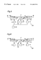
In a component mounting apparatus for mounting electronic components onto a printed board, a portion which executes securing and holding of the printed board in the stage of mounting the electronic components is constructed as follows. That is, as shown in FIGS. 7 and 8, a circuit board holding apparatus 1 for securing and holding a printed board 2 is provided on an X-Y table for moving the printed board 2 in X- and Y-directions. On the circuit board holding apparatus 1 is fixed a pair of stationary members 13 which extend parallel to the X-direction and have an approximately inverted L-like sectional shape. Also provided are a pair of movable members 14 which extend in the X-direction along inner side surfaces 13 a of the stationary members 13 and oppose each other at both the stationary members 13 and slide in a Z-direction between a board gripping position 20 and a board releasing position 21 while being guided along the inner side surfaces 13 a. In such a circuit board holding apparatus 1, the printed board 2 is conveyed into a region between both the stationary members 13. Then, by moving upward both of the movable members 14 into the board gripping position 20 by means of drive units 15 having, for example, an air cylinder, the edge portions 2 a of the printed board 2 extending in the X-direction are gripped by board contact surfaces 13 b of the stationary members 13 and board contact surfaces 14 b of the movable members 14, so that the printed board 2 is secured to the circuit board holding apparatus 1.
The X-Y table on which the printed board 2 is secured in this manner is moved into a specified position in the X- and Y-directions, and mounting of electronic components onto the printed board 2 is executed by an electronic component mounting unit 3. After the operation of mounting specified electronic components onto the printed board 2 is completed, the drive units 15 are operated to move the movable members 14 downward to the board releasing position 21 as shown in FIG. 9, where the gripping of the printed board 2 is released and the printed board 2 is conveyed to the next process.
However, in the aforementioned circuit board holding apparatus 1, there may occur a phenomenon that the printed board 2 sticks to the stationary members 13 as shown in FIG. 10 depending on the surface conditions of the printed board 2 in spite of the fact that the movable members 14 have been moved down to the board releasing position 21. That is, it is sometimes the case where a rubber material is attached or coated on the board contact surface 13 b of the stationary member 13 and the board contact surface 14 b of the movable member 14 for the purpose of increasing the frictional force between the stationary member 13 and the movable member 14 and the printed board 2 so that the displacement of the printed board 2 should not occur in the X-direction in the state in which the printed board 2 is gripped. Therefore, in the case where a flux is coated on the front and rear surfaces of the printed board 2 or in a similar case, the aforementioned rubber material and the front and rear surfaces of the printed board 2 might stick to each other due to the aforementioned gripping operation. After such a stuck state has occurred, the printed board 2 falls onto the movable members 14 side by its own gravity. However, this disadvantageously causes a state in which the positions of the electronic components mounted on the printed board 2 are displaced by the falling of the printed board 2, a state in which the printed board 2 cannot be conveyed to the next process or a similar state.
SUMMARY OF THE INVENTION
The present invention has been developed to solve the above issue and provide a circuit board holding apparatus which prevents the occurrence of displacement of the mounted electronic components and the state in which the printed board cannot be conveyed to the next process after the electronic components have been mounted onto the circuit board, and a circuit board hold releasing method to be executed by the circuit board holding apparatus.
In accomplishing these and other aspects, according to a first aspect of the present invention, there is provided a circuit board holding apparatus for holding a circuit board by gripping a pair of opposed edge portions of a circuit board, comprising:
stationary members which are arranged opposite the edge portions and contact a front surface of the circuit board;
movable members which contact a rear surface of the circuit board and grip each of the edge portions of the circuit board between the movable member and the stationary member in a direction of thickness of the circuit board by moving into a board gripping position, the movable members moving in the direction of thickness of the circuit board between the board gripping position and a board releasing position; and
a separation mechanism for forcibly separating the circuit board from the stationary members when the movable members move from the board gripping position to the board releasing position for releasing the hold of the circuit board.
According to a second aspect of the present invention, there is provided a circuit board holding apparatus as defined in the first aspect, wherein the separation mechanism is a pressing member which is mounted to the stationary member and puts the circuit board into pressure contact with the movable member.
According to a third aspect of the present invention, there is provided a circuit board holding apparatus as defined in the second aspect, wherein, when the front and rear surfaces of the circuit board are located upward and downward and the movable member moves in a vertical direction, the pressing member is an elastic member having one end-portion to be fixed to the stationary member and the other end portion which is to contact the front surface of the circuit board and presses the circuit board against the movable member.
According to a fourth aspect of the present invention, there is provided a circuit board holding apparatus as defined in the first aspect, wherein the separation mechanism is a suction unit having a suction section which is arranged on the rear surface side of the circuit board and attracts by suction the rear surface of the circuit board, and a drive unit which moves the suction section in a direction in which the movable member moves together with the moving of the movable member.
According to a fifth aspect of the present invention, there is provided a circuit board holding apparatus as defined in the fourth aspect, further comprising a control unit which controls the start of the moving of the movable member from the board gripping position the into the board releasing position, start of the sucking of the circuit board by the suction unit, and the moving of the suction unit by means of the drive unit.
According to a sixth aspect of the present invention, there is provided a circuit board hold releasing method to be executed by a circuit board holding apparatus which grips a pair of opposed edge portions of a circuit board in a direction of thickness of the circuit board by means of a stationary member and a movable member moving between a board gripping position and a board releasing position, thereby holding the circuit board, comprising:
moving the movable member into the board releasing position in a process of releasing the gripping of the circuit board; and
making the circuit board contact the movable member together with the moving of the movable member toward the board releasing position side.
BRIEF DESCRIPTION OF THE DRAWINGS
These and other aspects and features of the present invention will become clear from the following description taken in conjunction with the preferred embodiments thereof with reference to the accompanying drawings, in which:
FIG. 1 is a perspective view showing the total construction of a circuit board holding apparatus according to an embodiment of the present invention;
FIG. 2 is a side view showing a state in which a pressing member shown in FIG. 1 is mounted to a stationary member;
FIG. 3 is a side view showing a state in which movable members are arranged in a board gripping position in the circuit board holding apparatus shown in FIG. 1;
FIG. 4 is a side view showing a state in which the movable members are arranged in a board releasing position in the circuit board holding apparatus shown in FIG. 1;
FIG. 5 is a side view showing a circuit board holding apparatus according to a second embodiment of the present invention in a state in which movable members are arranged in a board gripping position;
FIG. 6 is a side view showing a state in which the movable members are arranged in a board releasing position in the circuit board holding apparatus shown in FIG. 5;
FIG. 7 is a perspective view showing the overall construction of a prior art circuit board holding apparatus;
FIG. 8 is a side view showing a state in which movable members are arranged in a board gripping position in the circuit board holding apparatus shown in FIG. 7;
FIG. 9 is a side view showing a state in which movable members are arranged in a board releasing position in the circuit board holding apparatus shown in FIG. 7; and
FIG. 10 is a side view showing a state in which a printed board is stuck to the stationary member side in the circuit board holding apparatus shown in FIG. 7.
DETAILED DESCRIPTION OF THE INVENTION
Before the description of the present invention proceeds, it is to be noted that like parts are designated by like reference numerals throughout the accompanying drawings.
A circuit board holding apparatus and a circuit board hold releasing method according to an embodiment of the present invention will be described below with reference to the drawings. It is to be noted that the circuit board hold releasing method is executed by the circuit board holding apparatus. Further, identical components are denoted by the same reference numerals in the figures.
As shown in FIG. 1, on upper surfaces 13 c of stationary members 13 of a circuit board holding apparatus 100 of the present embodiment are mounted four L-shaped pressing members 7, two of which are arranged on the upper surface 13 c of one of the stationary member 13, and two of which are arranged on the upper surface 13 c of the other one of the stationary member 13, so that they are located at the four corners of a printed board 2, which is an example of a circuit board in the present invention. It is to be noted that the pressing member 7 is an example of a separating mechanism in the present invention. The pressing member 7 is an elastic member formed by integrating a fixing section 71 with a contact section 72 which bends toward the printed board 2 side with respect to the fixing section 71 as shown in FIG. 2. The fixation section 71 has a length slightly greater than a width dimension W of the upper surface 13 c, and as described later, it extends in contact with the upper surface 13 c when the movable member 14 is in the board releasing position 21. Such a fixing section 71 is mounted to the upper surface 13 c of the stationary member 13 by means of a screw 8 at one end portion 7 a of the pressing member 7 located on the side opposite the contact section 72. Therefore, the pressing member 7 is fixed to the stationary member 13. The contact section 72 extends downward by a dimension L beyond the board contact surface 13 b of the stationary member 13. Therefore, as described later, when the movable member 14 is located near the board gripping position 20, the other end portion 7 b of the pressing member 7 contacts the front surface 2 b of the printed board 2 arranged on the upper side.
The operation of the pressing members 7 constructed as above will be described below.
Similarly to the aforementioned prior art, after the printed board 2 is conveyed into the region between the stationary members 13, the movable members 14 are moved upward by the operation of drive units 15, and the edge portions 2 a of the printed board 2 are gripped by the board contact surfaces 13 b of the stationary members 13 and the board contact surfaces 14 b of the movable members 14 as shown in FIG. 3. The pressing member 7 has its one end portion 7 a fixed to the stationary member 13 by means of the screw 8 and has the other end portion 7 b protruded by the dimension L below the board contact surface 13 b. Therefore, the front surface 2 b of the printed board 2 and the other end portion 7 b contact each other just before the edge portion 2 a of the printed board 2 is completely gripped. When the printed board 2 is completely gripped by the stationary member 13 and the movable member 14, the fixing section 71 of the pressing member 7 warps upward with the point fixed by the screw 8 serving as a fulcrum. Therefore, in the state in which the printed board 2 is gripped by the stationary member 13 and the movable member 14, the other end portion 7 b presses the front surface 2 b of the printed board 2 downward, i.e., toward the movable member side by the elastic force of the pressing member 7.
Similarly to the prior art, after the electronic components are mounted to the printed board 2 as described above, the movable members 14 move downward with the left and right drive units 15 synchronized with each other in operation. In this stage, the two edge portions 2 a of the printed board 2 are forcibly toward the movable member side by the other end portions 7 b of the pressing members 7. Therefore, even when the front surface 2 b of the printed board 2 is in the state in which it is stuck to the board contact surfaces 13 b of the stationary members 13, the stuck state is released by the pressure forces of the pressing members 7, so that the stationary members 13 and the printed board 2 are separated from each other. Therefore, as shown in FIG. 4, the printed board 2 moves downward together with the movable members 14 in a state in which it is forcibly made to contact the movable members 14. By thus providing the pressing members 7, the state in which the printed board 2 remains stuck to the board contact surfaces 13 b of the stationary members 13 in spite of the fact that the movable member 14 has moved down can be prevented from occurring. Therefore, the phenomenon that the positions of the mounted electronic components are displaced by the subsequent falling of the printed board 2 onto the movable members 14 and the phenomenon that trouble occurs in conveying the printed board 2 to the next process can be prevented from occurring.
The aforementioned pressure force of the pressing member 7 can be varied according to the design conditions of the material, thickness, aforementioned dimension L and the like of the pressing member 7, and it is proper to set the above design conditions to appropriate values according to the adhesion force exerted between the printed board 2 and the stationary member 13.
Furthermore, the pressing members 7 are arranged in the positions corresponding to the four corners of the printed board 2 in the present embodiment as shown in FIG. 1. However, being not limited to this, the pressing members 7 may be arranged continuously along the edge portion 2 a of the printed board 2.
Furthermore, the pressing member 7 has the L-like leaf spring configuration as illustrated in the present embodiment. However, the member 7 is not limited to this. That is, the member 7 is only required to be an elastic member having one end portion to be fixed to the stationary member 13 and the other end portion which is to contact the front surface 2 b of the printed board 2 and presses the printed board 2 toward the movable member 14. There can be considered a structure provided by a coil spring for performing the aforementioned pressing operation by the elastic force of the spring, or a structure using an elastic material such as a rubber material and the like.
Furthermore, it is acceptable to adopt a mechanism in which the one end portion is mounted to a member other than the stationary member 13 and the other end portion contacts the printed board 2 and presses the printed board 2 toward the movable member 14, i.e., a separation mechanism for separating the printed board 2 from the stationary member 13.
Furthermore, the front surface 2 b of the printed board 2 is arranged on the upper side and the rear surface 2 c is arranged on the lower side in the present embodiment. However, it is acceptable to arrange the front and rear surfaces 2 b and 2 c of the printed board 2 parallel to the vertical direction and grip the printed board 2 laterally with respect to the vertical direction by the stationary member 13 and the movable member 14.
Next, a circuit board holding apparatus 101 according to a second embodiment will be described below.
In this embodiment, in order to forcibly make the printed board 2 contact the movable member 14 when the movable member 14 is moved downward in the stage for releasing the hold of the printed board 2, a suction unit 12 for attracting by suction the rear surface 2 c of the printed board 2 is provided as another example of the separation mechanism in place of the aforementioned pressing members 7.
A concrete description will be made. On the rear surface side of the printed board 2 on the X-Y table is provided the suction unit 12 for attracting the printed board 2 by suction at a suction area which does not interfere with the mounting of electronic components onto the printed board 2. As the above suction area, for example, the four corners, a center portion or the like of the printed board 2 can be used. It is to be noted that the suction area is only one center portion of the printed board 2 in this embodiment. The suction unit 12 is provided with a suction pad 120 for attracting by suction the suction area of the printed board 2, a drive unit 121 having, for example, an air cylinder for moving the suction pad 120 upward and downward, and a vacuum unit 123 which is connected to the suction pad 120 by means of a suction hose and which executes a suction operation. Further, in order to synchronize the operation of the drive units 15 for vertically moving the movable members 14 with the operation of the drive unit 121 for vertically moving the suction pad 120 and controlling the suction operation, a control unit 122 to be electrically connected to the drive units 15, the drive unit 121, and the vacuum unit 123 is provided. It is to be noted that the control unit 122 is not shown in FIG. 6.
The operation of the circuit board holding apparatus 101 of the second embodiment having the above construction will be described below.
Similarly to the aforementioned case, after the printed board 2 has been gripped by the stationary member 13 and the movable member 14 and had electronic components mounted thereon, the suction pad 120 moves upward until it will be made to contact the rear surface 2 c of the printed board 2 by the operation of the drive unit 121 before the movable members 14 will be moved downward by the operation of the drive units 15. Then, before the movable members 14 are moved downward or simultaneously with the start of the downward movement, the suction of the printed board 2 is started by the vacuum unit 123. Thus, by starting the suction of the printed board 2, the printed board 2 is forcibly made to contact the movable members 14. It is to be noted that the operations of the drive units 15 for the movable members 14, the drive unit 121 for the suction pad 120, and the vacuum unit 123 are controlled by the control unit 122.
Therefore, even when the front surface 2 b of the printed board 2 is in the state in which it is stuck to the board contact surfaces 13 b of the stationary members 13, the stuck state is released by the suction force of the vacuum unit 123. Consequently, as shown in FIG. 6, the printed board 2 moves downward together with the movable members 14 in the state in which the printed board 2 is forcibly made to contact the movable members 14. It is to be noted that the suction operation of the printed board 2 is stopped under the control of the control unit 122 at the point in time when the movable members 14 have moved downward by a specified distance from the board gripping position 20 into the board releasing position 21 or after they have completed the downward movement into the board releasing position 21. By thus providing the suction unit 12, the printed board 2 can be prevented from falling onto the movable members 14, so that the displacement of the arrangement of the already mounted electronic components and the occurrence of trouble in conveying the printed board 2 to the next process can be prevented.
It is also acceptable to arrange the front and rear surfaces 2 b and 2 c of the printed board 2 parallel to the vertical direction and grip the printed board 2 laterally with respect to the vertical direction by the stationary member 13 and the movable member 14 in this second embodiment.
The movable members 14 are driven by the respective drive units 15. However, being not limited to this, both the movable members 14 may be driven by one drive unit.
Furthermore, as another embodiment of the separation mechanism, it is acceptable to adopt a mechanism in which, for example, a pawl member to be engaged with the printed board 2 is provided and the printed board 2 is forcibly made to contact the movable members 14 by engaging the pawl member with the printed board 2 when releasing the hold of the printed board 2, i.e., a mechanism in which the printed board 2 is forcibly separated from the stationary members 13.
As described in detail above, according to the circuit board holding apparatus of the present invention and the circuit board hold releasing method of the present invention, there is provided the separation mechanism for forcibly separating the circuit board from the stationary member when the movable member moves from the board gripping position to the board releasing position during releasing of the hold of the circuit board achieved by the stationary member and the movable member. With this arrangement, even when the circuit board is in the state in which it is stuck to the stationary member, the circuit board is forcibly released from the stuck state and moved downward together with the movable member. Therefore, the stationary member does not fall onto the movable member after the movable member has moved downward to the board releasing position, so that displacement of the positions of the electronic components mounted on the circuit board or a state in which the circuit board cannot be conveyed to the next process can be prevented from occurring.
The entire disclosure of Japanese Patent Application No. 8-161951 filed on Jun. 21, 1996, including specification, claims, drawings, and summary are incorporated herein by reference in its entirety.
Although the present invention has been fully described in connection with the preferred embodiments thereof with reference to the accompanying drawings, it is to be noted that various changes and modifications are apparent to those skilled in the art. Such changes and modifications are to be understood as included within the scope of the present invention as defined by the appended claims unless they depart therefrom.

Claims (9)

What is claimed is:
1. A circuit board holding apparatus for holding a circuit board by gripping a pair of opposed edge portions of the circuit board, comprising:
stationary members to be arranged opposite the edge portions of the circuit board for contacting a front surface of the circuit board;
movable members movable with respect to said stationary members between a board gripping position in which the edge portions of the circuit board are gripped between said movable members and said stationary members when the circuit board is disposed therebetween, and a board releasing position, for contacting a rear surface of the circuit board and moving the circuit board in a thickness direction thereof when said movable members move from said board releasing position toward said board gripping position; and
a separation mechanism for forcibly separating the circuit board from said stationary members in a direction of movement of said movable members when said movable members move from said board gripping position to toward said board releasing position to release the circuit board from said stationary members;
wherein said separation mechanism comprises at least one pressing member mounted to one of said stationary members to cause the circuit board to be put in pressure contact with at least one of said movable members.
2. A circuit board holding apparatus as claimed in claim 1, wherein
said at least one pressing member comprises an elastic member having one end portion fixed to said one of said stationary members and the other end portion which is to contact the front surface of the circuit board to press the circuit board against said at least one of said movable members when said movable members are in said board gripping position.
3. A circuit board holding apparatus as claimed in claim 2, wherein
when the front and rear surfaces of the circuit board are faced upwardly and downwardly, respectively, said movable member is movable vertically.
4. A circuit board holding apparatus as claimed in claim 3, wherein
said separation mechanism operates to separate the circuit board from said stationary members on confronting sides of the circuit board when said movable members move from said board gripping position toward said board releasing position.
5. A circuit board holding apparatus as claimed in claim 1, wherein
said separation mechanism comprises a pair of pressing members mounted to each of said stationary members to cause the circuit board to be in pressure contact with each of said movable members.
6. A circuit board holding apparatus as claimed in claim 1, wherein
said separation mechanism comprises at least one pressing member mounted to each of said stationary members to cause the circuit board to be in pressure contact with each of said movable members.
7. A circuit board holding apparatus as claimed in claim 1, wherein
said separation mechanism operates to separate the circuit board from said stationary members on confronting sides of the circuit board when said movable members move from said board gripping position toward said board releasing position.
8. A circuit board holding apparatus for holding a circuit board by gripping a pair of opposed edge portions of the circuit board, comprising:
stationary members to be arranged opposite the edge portions of the circuit board for contacting a front surface of the circuit board;
movable members movable with respect to said stationary members between a board gripping position in which the edge portions of the circuit board are gripped between said movable members and said stationary members when the circuit board is disposed therebetween, and a board releasing position, for contacting a rear surface of the circuit board and moving the circuit board in a thickness direction thereof when said movable members move from said board releasing position toward said board gripping position; and
a separation mechanism for forcibly separating the circuit board from said stationary members in a direction of movement of said movable members when said movable members move from said board gripping position toward said board releasing position to release the circuit board from said stationary members;
wherein said separation mechanism comprises a suction unit including a suction section to be arranged on a rear surface side of the circuit board for attracting the rear surface of the circuit board by suction, and a drive unit which moves said suction section in the direction of movement of said movable members when said movable members are moved; and
wherein said separation mechanism operates to separate the circuit board from said stationary members on confronting sides of the circuit board when said movable members move from said board gripping position toward said board releasing position.
9. A circuit board holding apparatus for holding a circuit board by gripping a pair of opposed edge portions of the circuit board, comprising:
stationary members to be arranged opposite the edge portions of the circuit board for contacting a front surface of the circuit board;
movable members movable with respect to said stationary members between a board gripping position in which the edge portions of the circuit board are gripped between said movable members and said stationary members when the circuit board is disposed therebetween, and a board releasing position, for contacting a rear surface of the circuit board and moving the circuit board in a thickness direction thereof when said movable members move from said board releasing position toward said board gripping position; and
a separation mechanism for forcibly separating the circuit board from said stationary members in a direction of movement of said movable members when said movable members move from said board gripping position toward said board releasing position to release the circuit board from said stationary members;
wherein said separation mechanism comprises a suction unit including a suction section to be arranged on a rear surface side of the circuit board for attracting the rear surface of the circuit board by suction, and a drive unit which moves said suction section in the direction of movement of said movable members when said movable members are moved;
wherein a control unit is provided to control a start of movement of said movable members from said board gripping position toward said board releasing position, a start of suction of the circuit board by said suction unit, and movement of said suction unit by said drive unit; and
wherein said separation mechanism operates to separate the circuit board from said stationary members on confronting sides of the circuit board when said movable members move from said board gripping position toward said board releasing position.
US09/202,420 1996-06-21 1997-06-19 Circuit board holding apparatus Expired - Lifetime US6206352B1 (en)

Priority Applications (1)

Application Number Priority Date Filing Date Title
US09/770,207 US6427313B2 (en) 1996-06-21 2001-01-29 Circuit board holding apparatus and circuit board hold releasing method

Applications Claiming Priority (3)

Application Number Priority Date Filing Date Title
JP16195196A JP3618020B2 (en) 1996-06-21 1996-06-21 Circuit board holding device and circuit board holding release method
JP8-161951 1996-06-21
PCT/JP1997/002103 WO1997049272A1 (en) 1996-06-21 1997-06-19 Circuit board holding apparatus and circuit board hold releasing method

Related Parent Applications (1)

Application Number Title Priority Date Filing Date
PCT/JP1997/002103 A-371-Of-International WO1997049272A1 (en) 1996-06-21 1997-06-19 Circuit board holding apparatus and circuit board hold releasing method

Related Child Applications (1)

Application Number Title Priority Date Filing Date
US09/770,207 Division US6427313B2 (en) 1996-06-21 2001-01-29 Circuit board holding apparatus and circuit board hold releasing method

Publications (1)

Publication Number Publication Date
US6206352B1 true US6206352B1 (en) 2001-03-27

Family

ID=15745161

Family Applications (2)

Application Number Title Priority Date Filing Date
US09/202,420 Expired - Lifetime US6206352B1 (en) 1996-06-21 1997-06-19 Circuit board holding apparatus
US09/770,207 Expired - Fee Related US6427313B2 (en) 1996-06-21 2001-01-29 Circuit board holding apparatus and circuit board hold releasing method

Family Applications After (1)

Application Number Title Priority Date Filing Date
US09/770,207 Expired - Fee Related US6427313B2 (en) 1996-06-21 2001-01-29 Circuit board holding apparatus and circuit board hold releasing method

Country Status (6)

Country Link
US (2) US6206352B1 (en)
EP (1) EP0906719B1 (en)
JP (1) JP3618020B2 (en)
CN (1) CN1110234C (en)
DE (1) DE69703932T2 (en)
WO (1) WO1997049272A1 (en)

Cited By (13)

* Cited by examiner, † Cited by third party
Publication number Priority date Publication date Assignee Title
US6346155B1 (en) * 1999-09-01 2002-02-12 Lucent Technologies Inc. Laser bar clamp
US6378857B1 (en) * 1999-02-23 2002-04-30 S.P. Precision International, Ltd Printed circuit board fixture
US6425577B1 (en) * 1999-08-09 2002-07-30 Essetre Di Sella Giovanni Fastening unit for blocking the items to be processed on the working plane of a woodworking tooling machine, and a tooling machine equipped with said unit
US6488060B1 (en) * 1999-08-09 2002-12-03 Essetre Di Sella Giovanni Woodworking tooling machine, capable of processing items of variable size and complex shape, and the relative method
US6527999B2 (en) 1998-10-07 2003-03-04 Micron Technology, Inc. Method for reducing warpage during application and curing of encapsulant materials on a printed circuit board
US6726195B1 (en) * 1998-10-13 2004-04-27 Dek International Gmbh Method for ensuring planarity when using a flexible, self conforming, workpiece support system
US20040083804A1 (en) * 2001-06-13 2004-05-06 Maute Robert E. Conductive fluid logging sensor and method
US20090159640A1 (en) * 2007-12-21 2009-06-25 Universal Scientific Industrial Co., Ltd. Wave soldering apparatus
US20110088257A1 (en) * 2008-06-12 2011-04-21 Adwelds Corporation Mounting apparatus
US8141237B1 (en) * 2010-10-30 2012-03-27 Cheng Uei Precision Industry Co., Ltd. Flexible printed circuit connector assembling fixture
EP2765843A3 (en) * 2013-02-06 2015-08-19 Yamaha Hatsudoki Kabushiki Kaisha Substrate fixing apparatus, substrate working apparatus and substrate fixing method
US20160288246A1 (en) * 2013-11-06 2016-10-06 Toshiba Mitsubishi-Electric Industrial Systems Corporation Electrode bonding apparatus and electrode bonding method
US10919710B2 (en) * 2015-10-27 2021-02-16 Hirata Corporation Transport unit, transfer apparatus, and transfer method

Families Citing this family (28)

* Cited by examiner, † Cited by third party
Publication number Priority date Publication date Assignee Title
KR20000001325A (en) * 1998-06-10 2000-01-15 유무성 Device for fixing printed circuit board of chip mounter
KR100348401B1 (en) * 2000-10-27 2002-08-10 미래산업 주식회사 Position Control Apparatus of Feeder Stage in Surface Mount Device
JP4546663B2 (en) * 2001-04-23 2010-09-15 富士機械製造株式会社 Printed board holding device and electrical component mounting system
KR20040027884A (en) * 2001-07-31 2004-04-01 아셈블레온 엔. 브이. Device for displacing printed circuit boards
US7032287B1 (en) * 2002-07-19 2006-04-25 Nanometrics Incorporated Edge grip chuck
JP4696450B2 (en) * 2004-01-21 2011-06-08 パナソニック株式会社 Screen printing device
US20060090327A1 (en) * 2004-10-29 2006-05-04 Garcia Eric D J Carrier ring comprising a plurality of springs
JP4857720B2 (en) * 2005-11-11 2012-01-18 パナソニック株式会社 Screen printing apparatus and screen printing method
US7549371B2 (en) * 2006-07-10 2009-06-23 Speedline Technologies, Inc. Method and apparatus for clamping a substrate
JP4687624B2 (en) * 2006-09-29 2011-05-25 オムロン株式会社 Substrate support device
JP4832281B2 (en) * 2006-12-28 2011-12-07 株式会社日立ハイテクインスツルメンツ Substrate transfer device
JP5434884B2 (en) * 2010-10-27 2014-03-05 パナソニック株式会社 Electronic component mounting apparatus and electronic component mounting method
US9218990B2 (en) * 2011-10-07 2015-12-22 Varian Semiconductor Equipment Associates, Inc. Method and apparatus for holding a plurality of substrates for processing
JP2014082232A (en) * 2012-10-12 2014-05-08 Omron Corp Fixing structure of planar body and substrate support device using the same
CN103787071A (en) * 2012-11-01 2014-05-14 凯吉凯精密电子技术开发(苏州)有限公司 Automatic grabbing method and device for circuit board
US9357686B2 (en) * 2013-11-14 2016-05-31 Illinois Tool Works Inc. Dispensing apparatus having substrate inverter system and clamping system, and method for dispensing a viscous material on a substrate
CN103990616B (en) * 2014-05-30 2017-03-15 苏州倍辰莱电子科技有限公司 Pcb board air blowing tool
CN104284553A (en) * 2014-10-13 2015-01-14 成都锐奕信息技术有限公司 Plug-in circuit board body installing system
CN104302136A (en) * 2014-10-13 2015-01-21 成都锐奕信息技术有限公司 Round box body used for circuit board body installation
CN104582461B (en) * 2015-01-19 2017-07-14 珠海嘉益电子科技有限公司 The fixing equipment of printed circuit board (PCB) and frame
CN104828601B (en) * 2015-04-30 2017-09-26 深圳市艾迪特智能装备有限公司 A kind of clamping device
KR101717682B1 (en) * 2015-06-08 2017-03-20 주식회사 로보스타 Robot for installing flexible bo and method controlling the same
JP2017220498A (en) * 2016-06-06 2017-12-14 パナソニックIpマネジメント株式会社 Component mounting equipment and component mounting method
CN106494072A (en) * 2016-10-21 2017-03-15 温州中科包装机械有限公司 Silk screen gluing non-stick web mechanism
CN108972057B (en) * 2018-08-13 2020-09-08 武汉光迅科技股份有限公司 A PCBA panel positioning and fixing device and method
WO2020093341A1 (en) * 2018-11-09 2020-05-14 李雪艳 Pcb board bracket having protection function
CN109759975A (en) * 2019-03-21 2019-05-17 成都飞机工业(集团)有限责任公司 A kind of positioning fixture of augmented reality artificial target's object of aircraft freight space auxiliary operation
CN113369722B (en) * 2021-04-30 2023-03-10 武汉华工激光工程有限责任公司 Clap clamp plate structure, feeding mechanism and IC support plate processing equipment

Citations (7)

* Cited by examiner, † Cited by third party
Publication number Priority date Publication date Assignee Title
US1850806A (en) * 1930-04-21 1932-03-22 Joseph M Noel Button spacer
US4700488A (en) * 1985-02-14 1987-10-20 Ezio Curti Arrangement for aligning a printed circuit substrate in a printing machine
US4928936A (en) * 1986-12-02 1990-05-29 Nikon Corporation Loading apparatus
US4951240A (en) 1985-12-02 1990-08-21 Mitsubishi Denki Kabushiki Kaisha Electronic part mounting system for printed circuit board
EP0392516A2 (en) 1989-04-11 1990-10-17 Tokyo Electron Limited Plasma processing device
US5580415A (en) * 1994-04-19 1996-12-03 Diekwisch; Hartmut Membrane press work base
US5916689A (en) * 1995-01-12 1999-06-29 Applied Materials, Inc. Electrostatic chuck with an impregnated, porous layer that exhibits the Johnson-Rahbeck effect

Patent Citations (7)

* Cited by examiner, † Cited by third party
Publication number Priority date Publication date Assignee Title
US1850806A (en) * 1930-04-21 1932-03-22 Joseph M Noel Button spacer
US4700488A (en) * 1985-02-14 1987-10-20 Ezio Curti Arrangement for aligning a printed circuit substrate in a printing machine
US4951240A (en) 1985-12-02 1990-08-21 Mitsubishi Denki Kabushiki Kaisha Electronic part mounting system for printed circuit board
US4928936A (en) * 1986-12-02 1990-05-29 Nikon Corporation Loading apparatus
EP0392516A2 (en) 1989-04-11 1990-10-17 Tokyo Electron Limited Plasma processing device
US5580415A (en) * 1994-04-19 1996-12-03 Diekwisch; Hartmut Membrane press work base
US5916689A (en) * 1995-01-12 1999-06-29 Applied Materials, Inc. Electrostatic chuck with an impregnated, porous layer that exhibits the Johnson-Rahbeck effect

Cited By (21)

* Cited by examiner, † Cited by third party
Publication number Priority date Publication date Assignee Title
US20050087909A1 (en) * 1998-10-07 2005-04-28 Gochnour Derek J. Method for reducing warpage during application and curing of encapsulant materials on a printed circuit board
US6764549B2 (en) 1998-10-07 2004-07-20 Micron Technology, Inc. Method and apparatus for reducing warpage during application and curing of encapsulant materials on a printed circuit board
US7166252B2 (en) 1998-10-07 2007-01-23 Micron Technology, Inc. Method for reducing warpage during application and curing of encapsulant materials on a printed circuit board
US6830719B2 (en) 1998-10-07 2004-12-14 Micron Technology, Inc. Method for reducing warpage during application and curing of encapsulant materials on a printed circuit board
US6527999B2 (en) 1998-10-07 2003-03-04 Micron Technology, Inc. Method for reducing warpage during application and curing of encapsulant materials on a printed circuit board
US6592670B1 (en) * 1998-10-07 2003-07-15 Micron Technology, Inc. Apparatus for reducing warpage during application and curing of encapsulant materials on a printed circuit board
US6726195B1 (en) * 1998-10-13 2004-04-27 Dek International Gmbh Method for ensuring planarity when using a flexible, self conforming, workpiece support system
US6378857B1 (en) * 1999-02-23 2002-04-30 S.P. Precision International, Ltd Printed circuit board fixture
US6488060B1 (en) * 1999-08-09 2002-12-03 Essetre Di Sella Giovanni Woodworking tooling machine, capable of processing items of variable size and complex shape, and the relative method
US6425577B1 (en) * 1999-08-09 2002-07-30 Essetre Di Sella Giovanni Fastening unit for blocking the items to be processed on the working plane of a woodworking tooling machine, and a tooling machine equipped with said unit
US6346155B1 (en) * 1999-09-01 2002-02-12 Lucent Technologies Inc. Laser bar clamp
US20040083804A1 (en) * 2001-06-13 2004-05-06 Maute Robert E. Conductive fluid logging sensor and method
US20090159640A1 (en) * 2007-12-21 2009-06-25 Universal Scientific Industrial Co., Ltd. Wave soldering apparatus
US20110088257A1 (en) * 2008-06-12 2011-04-21 Adwelds Corporation Mounting apparatus
US8910375B2 (en) * 2008-06-12 2014-12-16 Adwelds Corporation Mounting apparatus
US8141237B1 (en) * 2010-10-30 2012-03-27 Cheng Uei Precision Industry Co., Ltd. Flexible printed circuit connector assembling fixture
EP2765843A3 (en) * 2013-02-06 2015-08-19 Yamaha Hatsudoki Kabushiki Kaisha Substrate fixing apparatus, substrate working apparatus and substrate fixing method
TWI583606B (en) * 2013-02-06 2017-05-21 山葉發動機股份有限公司 Substrate fixing apparatus, substrate working apparatus, and substrate fixing method
US9668393B2 (en) 2013-02-06 2017-05-30 Yamaha Hatsudoki Kabushiki Kaisha Substrate fixing apparatus and substrate working apparatus
US20160288246A1 (en) * 2013-11-06 2016-10-06 Toshiba Mitsubishi-Electric Industrial Systems Corporation Electrode bonding apparatus and electrode bonding method
US10919710B2 (en) * 2015-10-27 2021-02-16 Hirata Corporation Transport unit, transfer apparatus, and transfer method

Also Published As

Publication number Publication date
DE69703932D1 (en) 2001-02-22
US20010004795A1 (en) 2001-06-28
EP0906719B1 (en) 2001-01-17
WO1997049272A1 (en) 1997-12-24
US6427313B2 (en) 2002-08-06
CN1110234C (en) 2003-05-28
CN1222289A (en) 1999-07-07
DE69703932T2 (en) 2001-09-06
JPH1013099A (en) 1998-01-16
JP3618020B2 (en) 2005-02-09
EP0906719A1 (en) 1999-04-07

Similar Documents

Publication Publication Date Title
US6206352B1 (en) Circuit board holding apparatus
US6000122A (en) Component suction head for electronic component mounting machines
KR20010111592A (en) Method and device for placing components on substrates
JP3314663B2 (en) Chip bonding equipment
JP3438067B2 (en) Heald extrusion separation method and apparatus
JPH07132478A (en) Vacuum suction method and suction device
JP2008155557A (en) Printing method and printing device
JP2514437B2 (en) Alignment method for thin-walled substrates in screen printing process
JPH0377288A (en) IC socket
JPH10313042A (en) Collet
JPH03147637A (en) Separation of superposed thin piece and device therefor
JP2719310B2 (en) Plate-like member supply method and apparatus
JPH01214039A (en) Component suction pad structure
CN223182470U (en) Home appliance panel structure that facilitates bonding and positioning
JP2002141395A (en) Substrate presence/absence confirmation method and equipment for holding substrate
KR200150166Y1 (en) Absorbing machine
TWI909781B (en) Pick-up device
KR20250003351A (en) Stencil printer
JPS6164190A (en) Inserting head of printed substrate assembling machine
JPH0126159Y2 (en)
JP3520642B2 (en) Panel material separating apparatus and panel material separating method
JPS61197334A (en) Separation lifter
JPH02207599A (en) Device for regulating attitude of electronic component
JPS61254434A (en) Suction unit
JPH04122483U (en) Gripper for separating connector rubber

Legal Events

Date Code Title Description
AS Assignment

Owner name: MATSUSHITA ELECTRIC INDUSTRIAL CO., LTD., JAPAN

Free format text: ASSIGNMENT OF ASSIGNORS INTEREST;ASSIGNORS:ISHITANI, YASUYUKI;SENO, MAKITO;REEL/FRAME:010048/0645

Effective date: 19981028

STCF Information on status: patent grant

Free format text: PATENTED CASE

FPAY Fee payment

Year of fee payment: 4

FPAY Fee payment

Year of fee payment: 8

FEPP Fee payment procedure

Free format text: PAYOR NUMBER ASSIGNED (ORIGINAL EVENT CODE: ASPN); ENTITY STATUS OF PATENT OWNER: LARGE ENTITY

FEPP Fee payment procedure

Free format text: PAYER NUMBER DE-ASSIGNED (ORIGINAL EVENT CODE: RMPN); ENTITY STATUS OF PATENT OWNER: LARGE ENTITY

Free format text: PAYOR NUMBER ASSIGNED (ORIGINAL EVENT CODE: ASPN); ENTITY STATUS OF PATENT OWNER: LARGE ENTITY

FPAY Fee payment

Year of fee payment: 12