US6185828B1 - Position signal transmitter for a servo drive - Google Patents
Position signal transmitter for a servo drive Download PDFInfo
- Publication number
- US6185828B1 US6185828B1 US09/206,650 US20665098A US6185828B1 US 6185828 B1 US6185828 B1 US 6185828B1 US 20665098 A US20665098 A US 20665098A US 6185828 B1 US6185828 B1 US 6185828B1
- Authority
- US
- United States
- Prior art keywords
- shaft
- switching
- housing
- switching member
- gearing
- Prior art date
- Legal status (The legal status is an assumption and is not a legal conclusion. Google has not performed a legal analysis and makes no representation as to the accuracy of the status listed.)
- Expired - Fee Related
Links
Images


Classifications
-
- F—MECHANICAL ENGINEERING; LIGHTING; HEATING; WEAPONS; BLASTING
- F16—ENGINEERING ELEMENTS AND UNITS; GENERAL MEASURES FOR PRODUCING AND MAINTAINING EFFECTIVE FUNCTIONING OF MACHINES OR INSTALLATIONS; THERMAL INSULATION IN GENERAL
- F16K—VALVES; TAPS; COCKS; ACTUATING-FLOATS; DEVICES FOR VENTING OR AERATING
- F16K37/00—Special means in or on valves or other cut-off apparatus for indicating or recording operation thereof, or for enabling an alarm to be given
- F16K37/0008—Mechanical means
-
- F—MECHANICAL ENGINEERING; LIGHTING; HEATING; WEAPONS; BLASTING
- F16—ENGINEERING ELEMENTS AND UNITS; GENERAL MEASURES FOR PRODUCING AND MAINTAINING EFFECTIVE FUNCTIONING OF MACHINES OR INSTALLATIONS; THERMAL INSULATION IN GENERAL
- F16K—VALVES; TAPS; COCKS; ACTUATING-FLOATS; DEVICES FOR VENTING OR AERATING
- F16K37/00—Special means in or on valves or other cut-off apparatus for indicating or recording operation thereof, or for enabling an alarm to be given
- F16K37/0025—Electrical or magnetic means
- F16K37/0041—Electrical or magnetic means for measuring valve parameters
Definitions
- the invention relates to a position signal transmitter or position signal generating device for indicating the rotational or angular position of the operating shaft of a servo drive
- the transmitter includes a housing that can be secured onto the servo drive, a rotatable switching shaft arranged in the housing and adapted to be coupled in a non-slip manner to the operating shaft of the servo drive, at least one switch arranged in the housing, and at least one switching cam that can be selectively positioned in a selected one of a plurality of angular positions and selectively fixed against relative rotation on the switching shaft, so that the switching cam operates the switch and thereby indicates the angular position of the switching shaft and therewith the operating shaft.
- Position signal transmitters of the above mentioned type are generally known, and are used in a variety of different applications for providing a feedback or answer-back indication of the end position of a member such as an armature that is movably operated by a servo drive.
- the servo drive for example, includes a through-going shaft that protrudes from one side of the servo drive to provide a drive shaft for the armature and protrudes from the other side of the servo drive to provide an operating shaft that rotates absolutely synchronously with the drive shaft.
- the signal transmitter also known as a position repeater or position feedback indicator, is coupled to the operating shaft to be operated absolutely synchronously with the rotational drive shaft of the servo drive.
- the dimensions of the protruding operating shaft as well as mounting holes provided on the side of the servo drive for securing the feet of the signal transmitter are standardized, to allow convenient coupling and mounting of the signal transmitter onto the servo drive.
- the switching cams or other switching elements are selectively positionable among a plurality of different angular positions relative to the angular position of the switching shaft. It is known to secure the switching cams or switching elements onto the shaft in a form-locking manner by providing a respective gearing for these respective components.
- the switching cams or switching elements are provided with an internal gearing, while area of the switching shaft is provided with an external gearing that meshes with the internal gearing of the switching cams or switching elements.
- a “gearing” simply refers to a series or set of gear teeth, which may have any known configuration.
- the switching shaft must further have a non-geared area adjacent to the externally geared area, and the switching cams or switching elements must be axially slidable off of the externally geared area and onto the non-geared area, where the switching cams or switching elements are then rotatable relative to the switching shaft to achieve the desired rotational adjustment. Then the switching cams are axially pushed back onto the externally geared area of the switching shaft in order to provide the necessary form-locking connection.
- a further manner of adjusting the switching cams is also known, whereby the switching cams are respectively provided with an end face gearing or spur gearing that respectively cooperates with a corresponding end face gearing or spur gearing provided on an offset shoulder of the switching shaft.
- An axially acting spring presses the two corresponding spur gearings into engagement with one another, which thereby causes a non-rotational connection, i.e. a connection that does not allow relative rotation, between the switching cam and the switching shaft.
- the switching cam In order to carry out a rotational adjustment of the switching cam, the switching cam can be pushed away from the spur gearing provided on the shaft, against the spring force, whereupon the switching cam is rotated into the desired rotational position and then released so that the spring force again pushes the cam into engagement with the spur gearing of the shaft to re-establish a form-locking connection therebetween without the application of any external force.
- the above mentioned brochure No. Z1-C-02-237 of the company “bar GmbH” discloses an arrangement in which the switches as well as further electrical or electronic components are pre-mounted on a mounting plate.
- the standardized mounting plate always has the same dimensions and two mounting holes adapted to receive mounting screws that are screwed into corresponding threaded holes provided in the floor of the housing.
- the problem remains that the arrangement of components on the mounting plate is variable and must be adapted to the individual needs of the respective ultimate user of the device in each case.
- the simplified assembly and wiring of the switches can only be achieved in combination with the serious disadvantage that a plurality of differently prepared mounting plate arrangements must be manufactured and stored in inventory in order to meet the needs of consumers of the device. This leads to high costs for the production and the inventory of the devices.
- the invention further aims to avoid or overcome the other disadvantages of the prior art, and to achieve additional advantages, as apparent from the present description.
- a position signal transmitter adapted to be coupled to a servo drive, comprising a housing, a switching shaft rotatably arranged within the housing, at least one switching member mounted on the switching shaft to be selectively fixed on the switching shaft to prevent relative rotation therebetween in a selected one of a plurality of rotational or angular positions, and a switch arranged in the housing so as to be operated or actuated by the switching member.
- the switching member and the switch may operate either mechanically or electromagnetically.
- the switching member may be a mechanical switching cam while the switch is a mechanical switch, or the switching member may be an electromagnetic or inductively detectable switching element that cooperates with an inductive switch.
- the inner wall surface of an opening in each switching member is provided with an internal gearing that can selectively be brought into engagement with at least one associated correspondingly externally geared section of the switching shaft.
- the switching shaft further includes non-geared or smooth cylindrical areas or sections adjacent to the externally geared sections.
- the externally geared section of the switching shaft is elastically movable, for example elastically depressible or deflectable, in a substantially radial direction toward the central rotational axis of the switching shaft.
- a first important feature of the invention is the combined provision of an internal gearing in an opening in the switching member such as a switching cam or electromagnetic switching element, cooperating with an external gearing provided on an elastically movable section of the switching shaft. Due to the elastic movability or deflectability of the externally geared section of the switching shaft, it is possible to selectively move the externally geared shaft section into or out of engagement with the internal gearing of the switching member.
- the externally geared section of the switching shaft is normally elastically pressed into engagement with the internal gearing of the switching member, which thus provides a form-locking intermeshing connection therebetween.
- the form-locking connection is maintained only for rotational moments or torques applied relatively between the switching member and the switching shaft up to a torque limit or threshold.
- the externally geared section of the shaft is automatically elastically deflected sufficiently to allow the switching member to rotate relative to the switching shaft.
- the externally geared, elastically movable section of the shaft acts as a selectively yielding detent that fixes the switching member against rotation only up to a certain applied rotational moment, but allows a slipping of the gears when a higher torque is applied.
- the rotational moment threshold or limit above which the detent arrangement allows relative rotation is greater than the relative rotational moments that arise during normal operation. More specifically, the rotational moments necessary for operating a mechanical switch in the case of the switching member being a mechanical switching cam are rather low, and substantially below the rotational moment limit or threshold, while the rotational moments necessary for operating an inductive contact-less switch in the case of the switching member being an inductively detectable switching element are approaching zero, and thus clearly well below the rotational moment limit or threshold.
- the torque threshold value can be designed or selected as desired, by appropriately selecting the configuration and material of the elastically movable externally geared section of the switching shaft, the slope angle of the gear teeth, the angular range and number of gear teeth included in the gearings, and the like.
- This radial displacement of the externally geared section of the shaft is enabled especially due to the sloping of the flanks of the individual gear teeth, which allow the respective opposed teeth of the internal gearing and of the external gearing to slide up on each other and then jump over into the next pitch engagement of the respective gear teeth. Namely, this allows a detented or pitch-by-pitch rotational slipping of the two components as long as a sufficiently large torque is applied to the switching member relative to the switching shaft.
- the switching member can freely rotate around the shaft, because the shaft does not include external gearing in areas other than the elastically deflectable section or sections.
- the remaining portion of the circumference of the shaft in the plane of the externally geared section is a smooth cylindrical shaft surface.
- the switching shaft is a hollow shaft
- the externally geared section is a tab or tongue-shaped elastically deflectable portion of the wall of the hollow shaft.
- the external gearing is provided on a tab or tongue that is connected to the rest of the wall of the hollow shaft by a web or stem.
- the externally geared deflectable section may have a substantially quadrilateral shape, whereby three sides are separated from the rest of the wall of the hollow shaft, and only one side is connected to or integrally extending from the wall of the hollow shaft through the connecting web. This provides a very simple structure for realizing the elastic deflectability of the externally geared section in a direction toward the central rotational axis of the switching shaft.
- the shaft Due to the construction of the shaft as a hollow shaft, the space required for radially deflecting the externally geared section toward the central rotational axis is readily available in the hollow core space within the hollow shaft. Also, the natural elastic characteristics of the material forming the externally geared section are used for providing the required elastic return force opposing the radial deflection. In view of achieving reduced manufacturing costs, it is especially advantageous if the spring-elastic part forming the externally geared section is separated from the rest of the wall of the hollow shaft by a simple U-shaped opening in the hollow wall. Such an opening can easily be formed in the hollow shaft during the injection molding fabrication of the shaft.
- a further feature of the invention allows the necessary torque to be applied to the switching members to carry out the desired rotational positional adjustment.
- the switching shaft is configured to have a groove with a semi-circular or semi-oval cross-sectional shape extending lengthwise parallel to the central rotational axis, with the groove opening as a slot along the outer surface of the shaft.
- the groove preferably extends from the free end of the shaft opposite the end that will be coupled to the servo drive, to the respective area at which the internal gearing of the respective switching member is located.
- a suitable externally geared adjusting tool can be inserted into this groove in such a manner that the tool's external gearing engages the internal gearing of the particular selected switching member that is to be adjusted, while it remains mounted on the shaft.
- the necessary torque can be applied to the switching member, while the handle end of the tool is as far outside the signal transmitting device as necessary for comfortable use thereof, without requiring disassembly of the components or a direct manipulation of the switching member itself.
- the position signal transmitter includes two switching members, i.e. switching cams or switching elements, arranged next to each other in the axial direction along the switching shaft, then there are also correspondingly two of the above described tool-access grooves provided diametrically opposite each other along the switching shaft.
- a diametrically opposed pair of the externally geared sections of the shaft wall are provided for engaging each respective one of the switching members, whereby the two respective pairs of externally geared sections of the shaft wall are displaced from each other in the axial direction so as to cooperate respectively with the two adjacently arranged switching members.
- the two diametrically opposite tool access grooves are uniformly circumferentially offset, i.e.
- the tool access grooves must be arranged circumferentially offset from each other and from the externally geared sections of the shaft wall at a different angular offset, other than 90°, in order to avoid a collision or conflict of the several tool access grooves and externally geared sections.
- the circumferential offset necessary will depend on the number of separate tool access grooves that are to be provided.
- each respective tool access groove In order to functionally link each respective tool access groove with a respective one of the switching members, the axial length of each tool access groove extends respectively to the plane of the internal gearing of a respective one of the switching members. In this manner, a selective or targeted adjustment of each selected individual one of the switching members can be carried out “one at a time” and independently of the others, simply by inserting the adjusting tool into the proper tool access groove associated with that selected switching member.
- each tool access groove has a particular axial length or depth corresponding to the axial position of the associated switching member, it is a very simple matter to simply insert the adjusting tool to the full depth or axial length of the respective groove, whereby the external gearing of the tool engages the internal gearing of the selected switching member, without having to judge the proper distance of inserting the tool so as to engage the proper one of the switching members.
- the adjusting tool can be used to reach and adjust both of the switching members individually, without interference by the respective other switching member. Namely, to adjust the rotational position of the bottom switching member, i.e. the switching member further from the free end of the shaft at which the tool is inserted, the tool is simply inserted into the appropriate corresponding tool access groove, and pushed through the central opening and past the internal gearing of the upper switching member, so as to finally bring the external gearing of the tool into engagement with the internal gearing of the lower switching member. In that arrangement, a non-geared shaft portion of the tool passes by the internal gearing of the upper switching member with a spacing therebetween, so that there is no engagement or interference between the tool and the upper switching member.
- a second important feature of the invention is that the mechanical and/or inductive switches are removably mounted on a base support plate, which in turn is connected to the housing in a form-locking manner in a plane perpendicular to the central rotational axis of the switching shaft, such that the base support plate together with the switches mounted thereon can be removed from the housing as a unit in the direction axially along the switching shaft.
- the switches and possibly other electrical or electronic components can be individually mounted on the base support plate while the plate is separate from, i.e. not mounted in, the housing.
- the component mounting and assembly step can be conveniently carried out outside of the confining or cramped space of the housing.
- a further reduction of the effort and expense of carrying out the assembly is achieved in that the individual switches may be mounted on and connected to the base support plate by means of elastic snap hooks.
- the base support plate may be manufactured as a standardized structural unit, in that it is provided with a plurality of snap hooks suitable for engaging different structural types and configurations of mechanical and/or inductive switches and other components.
- the production costs can be considerably reduced by such a standardized configuration.
- the standardized configuration will allow a reduced inventory to be maintained because it will no longer be necessary to keep on hand a supply of several different types or configurations of pre-assembled base plates, as was necessary in connection with the prior art position signal transmitters.
- a very advantageous embodiment of the position signal transmitter according to the invention is achieved when the housing is substantially cylindrical and the base support plate suitably fitted to the housing is essentially round.
- the inventive form-locking connection between the base support plate and the housing is achieved in a particularly elegant manner in that the base support plate is provided with recesses, openings or notches into which holding elements connected to the housing engage when the base support plate is in its mounted condition.
- These holding elements may also be embodied as snap hooks for example, so that the installation of the pre-assembled base support plate simply requires setting the base support plate into the housing and snapping it in place so as to be engaged by the snap hooks, without any further effort.
- FIG. 1 is an exploded view of a position signal transmitter according to the invention, including a housing, base support plate, switching shaft, and cover hood;
- FIG. 2 is a side view of the position signal transmitter according to FIG. 1, fully assembled
- FIG. 3 is a top view of the position signal transmitter according to FIG. 2;
- FIG. 4 is a sectional view of the position signal transmitter, taken along the section line IV—IV as shown in FIG. 3;
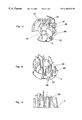
- FIG. 5 is a partially exploded perspective view of the switching shaft, two switching cams, and an adjusting tool, shown isolated or separated from the rest of the apparatus;
- FIG. 6 is a side view of the switching shaft of the position signal transmitter apparatus according to the invention.
- FIG. 7 is another side view of the switching shaft shown in FIG. 6, but rotated by 90°;
- FIG. 8 is another side view of the switching shaft of FIG. 6, but rotated by 180°;
- FIG. 9 is a sectional view of the switching shaft taken along the section line IX—IX as shown in FIG. 7;
- FIG. 10 is another sectional view of the switching shaft taken along the section line X—X as shown in FIG. 8;
- FIG. 11 is a perspective view of the base support plate according to the invention, as shown separate from the housing and other components of the present position signal transmitting apparatus;
- FIG. 12 is another perspective view of the base support plate of FIG. 11, as seen in a different view direction;
- FIG. 13 is a side view of the base support plate of FIG. 11 .
- FIG. 1 shows a general overview, in the manner of an exploded view, of a position signal transmitter 1 adapted to be connected to a servo drive, which is not shown.
- the position signal transmitter 1 essentially comprises a housing 2 , a base support plate 3 that can be inserted or installed in the housing 2 , a switching shaft 4 that is rotatably mountable in the housing 2 and is adapted to be coupled to and rotationally driven by an operating shaft of the servo drive, an indicator ring 5 , a cam sleeve 6 , and a cover hood 7 .
- Two stand-foot receivers 8 that are each respectively adapted to receive an angled stand-foot 9 are attached to the outside of the housing 2 at diametrically opposed locations.
- the stand-feet 9 which each respectively have a crowned or bulging cross-sectional shape, each include a plurality of paired holes 10 arranged one above the other. Snap-in bolts or studs 11 of a snap-in-place securing cover plate 12 can be selectively inserted through a respective pair of the holes 10 so as to secure the respective stand-foot 9 at the desired height in the foot receiver 8 . More particularly, the feet 9 can be arranged in two different positions in corresponding fitting recesses or grooves within the stand-foot receivers 8 . In one of the possible configurations, the respective stand-bases 13 of the two feet 9 are directed toward one another, while in the other configuration they are directed away from each other. In this manner, both the height of the signal transmitter 1 as well as the position and relative spacing between the holes 14 provided in the stand bases 13 for securing the position signal transmitter 1 onto the servo drive can be varied or adjusted to fit different standardized sizes of servo drives.
- the inner shell surface 18 of the housing 2 is provided with four guide grooves 17 that are correspondingly fitted to the guide rails 16 , such that the guide rails 16 are respectively axially slidably guided in the guide grooves 17 , so that the indicator ring 15 can move only in the axial direction.
- the cam sleeve 6 has a cam track 20 on the outer surface thereof, while the inner shell surface 19 of the indicator ring 5 has two cam track followers (not shown) thereon, which engage and followingly cooperate with the cam track 20 of the cam sleeve 6 .
- the cam track 20 is preferably a protruding cam rail, but it could equivalently be a cam groove let into the outer surface of the cam sleeve 6 . As shown in FIG. 1, the cam track 20 has a pattern of portions that slope alternately in opposite axial directions.
- the cam sleeve 6 is connected to the switching shaft 4 in a form-locking or form-engaging manner such that a rotation of the switching shaft 4 correspondingly rotates the cam sleeve 6 , whereby the cooperation of the cam track 20 of the cam sleeve 6 with the cam track followers provided on the inner surface 19 of the indicator ring 5 , which is further constrained by the guide rails 16 slidingly engaged in the guide grooves 17 , results in an axial movement of the indicator ring 5 .
- the above described axial movement of the indicator ring 5 resulting directly from a rotation of the switching shaft 4 gives a visual indication of the position of the servo drive, as follows.
- the cover hood 7 is preferably made of a transparent material, while at least the upper portion of the cam sleeve 6 is preferably colored a first clearly distinguishable color, such as red, while the indicator ring 5 is preferably colored a second clearly distinguishable color, such as green.
- the housing 2 is opaque, i.e. non-transparent.
- the indicator ring 5 In the first or bottom limit position, the indicator ring 5 will be completely covered or hidden within the opaque housing 2 , while the upper portion of the cam sleeve 6 will be exposed. Accordingly, in this position, the red upper portion of the cam sleeve 6 will be clearly visible through the transparent cover hood 7 . On the other hand, when the indicator ring 5 is in the second or top limit position, the green indicator ring 5 will cover the red cam sleeve 6 while itself being visible through the transparent cover hood 7 .
- FIGS. 2 and 3 show the assembled condition of the signal transmitter 1 , whereby the stand-feet 9 are arranged with the stand-bases 13 pointing outwardly away from each other.
- both the housing 2 and the cover hood 7 are substantially cylindrical or barrel-shaped.
- a lower end portion of the switching shaft 4 protrudes outwardly from the bottom surface 21 of the housing 2 and includes a coupling shaft stub 22 by which the switching shaft 4 may be coupled in a form-locking manner to an end of the operating shaft of the servo drive having a corresponding mating configuration.
- FIG. 4 further clarifies how the cam sleeve 6 is secured or supported on an upper portion of the switching shaft 4 in a manner preventing relative rotation therebetween.
- FIG. 4 shows the indicator ring 5 in the above described bottom limit position and further clarifies how a rotation of the switching shaft 4 will move the indicator ring 5 into the top limit position in which it surrounds or covers the upper portion of the cam sleeve 6 and thus becomes visible from the outside the transparent cover hood 7 .
- FIG. 4 further shows how the base support plate 3 is arranged on a floor 23 of the housing 2 in the installed condition. The pre-assembly of the base support plate 3 and its installation into the housing 2 will be further described below.
- FIG. 5 shows a perspective view of the switching shaft 4 , with a lower switching cam 24 A mounted thereon, and an upper switching cam 24 B removed or pulled off of the shaft 4 in an exploded view fashion, for clearly illustrating the externally geared section 29 B as will be described below.
- a generally rod-shaped adjusting tool 25 is illustrated, also in an exploded view fashion, in a position ready to be inserted into a tool access groove 34 B extending axially along the shaft 4 .
- the adjusting tool 25 includes a main tool shaft with an external gearing 26 provided on the bottom end thereof, and a handle or grip 27 provided at the upper end thereof.
- the two switching cams 24 A and 24 B are embodied as generally annular or ring-shaped cams, including a main ring body and a cam surface protruding therefrom.
- Each switching cam 24 A and 24 B has a central through-going hole therein, of which the inner wall surface is provided with an internal gearing 28 .
- the internal gearing 28 of each switching cam 24 A and 24 B respectively engages and cooperates with the external gearing of externally geared sections 29 A and 29 B of the switching shaft 4 , so that a form-locking or form-engaging connection arises between the switching shaft 4 and the switching cams 24 A and 24 B.
- the externally geared sections 29 A and 29 B of the switching shaft 4 include one pair of diametrically opposed lower sections 29 A and one pair of diametrically opposed upper sections 29 B.
- the respective paired upper sections 29 B are arranged axially above the paired lower sections 29 A with a small axial spacing therebetween.
- the externally geared sections 29 A and 29 B are each formed as a spring-elastically flexible part of the wall 31 of the switching shaft 4 , which is embodied as a hollow shaft.
- These tab or tongue-shaped sections 29 A and 29 B are preferably integrally formed with the wall 31 , in that they are respectively connected to the wall 31 integrally by a remaining connecting web 32 along one edge of the sections 29 A and 29 B, while three edges of the sections 29 A and 29 B respectively are formed and bounded by a generally U-shaped opening 33 in the wall 31 (see especially FIG. 7 and 9 ).
- the sections 29 A and 29 B are elastically deflectable in a generally radial direction toward the central rotational axis 30 of the switching shaft 4 .
- the resulting forces applied by the internal gear teeth of the switching cams 24 A and 24 B onto the external gear teeth of the sections 29 A and 29 B generate a radially directed force component that radially elastically deflects the sections 29 A and 29 B toward the central axis 30 to a sufficient extent to allow a ratcheting or detented rotational slipping of the internal gearing over the external gearing.
- the form-engaging connection between the internal gearing 28 of the switching cams 24 A and 24 B (see FIG. 5) and the external gearing of the sections 29 A and 29 B of the switching shaft 4 can be released or selectively overcome by applying a torque to the switching cams 24 A and 24 B that exceeds a certain specified torque limit or threshold.
- a rotationally fixed connection i.e. a connection preventing relative rotation, is maintained between the switching cams 24 A and 24 B and the switching shaft 4 .
- the switching cams 24 A and 24 B will be purposely rotated relative to the shaft in a pitch-by-pitch detented slipping manner.
- This detented rotational sliding or slipping of the gearings adjusts the angular position of the cams on the shaft and thereby also adjusts the respective switching angles.
- the degree of fine tuning that is achievable is determined by the pitch of the internal gearing of the switching cams 24 A and 24 B and the mating external gearing of the sections 29 A and 29 B.
- the application of the necessary torque for adjusting the rotational position of the switching cams 24 A and 24 B is achieved by means of the adjusting tool 25 shown in FIG. 5 .
- the externally geared end 26 of the tool 25 is positioned respectively circumferentially between two of the spring-elastic externally geared sections 29 A and 29 B and then brought into engagement with the internal gearing of the selected switching cam 24 A or 24 B.
- the required torque is applied to the engaged switching cam 24 A or 24 B so that it is rotated relative to the shaft 4 in a slipping, ratcheted or detented manner.
- two axially extending tool access grooves 34 A and 34 B are provided on two diametrically opposite sides of the hollow switching shaft 4 .
- a first one of the grooves 34 A has a longer axial length that extends all the way to the internal gearing 28 of the lower switching cam 24 A, while a second one of the grooves 34 B has a shorter axial length that only extends to the axial position of the internal gearing 28 of the upper switching cam 24 B.
- the adjusting tool 25 may be inserted into the respective groove 34 A or 34 B, all the way until the externally geared end 26 of the tool 25 comes to rest against the corresponding end stop surface 35 A or 35 B of the groove, at which point the externally geared end 26 of the tool 25 will be properly positioned for engaging the internal gearing 28 of the proper selected switching cam 24 A or 24 B.
- the externally geared end 26 of the tool 25 is simply pushed past the upper switching cam 24 B until it properly engages the lower switching cam 24 A as described above. In this manner, it is possible to adjust the rotational position of only the lower switching cam 24 A, if necessary, in the fully assembled condition of the signal transmitter 1 , without out first having to disassemble or reposition the upper switching can 24 B.
- the longer tool access groove 34 A preferably extends all the way to a circumferentially extending collar or band 36 , which thereby forms the stop surface 35 A.
- the lower switching cam 24 A in its installed position will be supported axially against this circumferential collar 36 , while the upper switching cam 24 B may in turn be axially supported against the lower switching cam 24 A.
- the base support plate 3 shown in FIGS. 11 to 13 serves as the supporting base on which the mechanical and/or inductive switches are mounted.
- the switches themselves are not shown in the drawings.
- These switches can be any conventional type of switch, that can be actuated by a mechanical switching cam or by an inductively detectable switching element, or even by an optically operating switching arrangement.
- the mechanical switching arrangement the cam surfaces of the switching cams 24 A and 24 B mechanically contact and run along a cam follower connected to the mechanical switch to achieve the switch operation, while the inductive switches are switched in a contact-less manner by the associated switching elements.
- switching cams 24 A and 24 B may, for example, be embodied by providing curved metal plates set into curved or ring-shaped pockets in the switching cams 24 A and 24 B, such that these metal plates can be detected or sensed by the inductive switches in a contact-free manner.
- one and the same assembly of the switching shaft with the switching cams arranged thereon can be used in connection with either mechanical switches or inductive switches, i.e. the switching cams with the curved metal plates embedded or inserted therein simultaneously serve the functions of a mechanical switching cam or a contact-free switching element.
- the base support plate 3 in its installed condition is arranged on the floor 23 of the housing 2 .
- the base support plate 3 is removable from the housing 2 in an axial direction.
- the several switches are first mounted on the base plate 3 , and thereafter the pre-assembled base plate arrangement is installed in the housing 2 by simply axially pushing it into the proper position in the housing.
- the base plate 3 is provided with three mounting holes 37 , which are each respectively surrounded and reinforced by a ring-shaped collar 38 .
- Appropriately configured bolt or pin-shaped holding elements protrude from the floor 23 of the housing 2 through these mounting holes 37 respectively, so as to provide a form-locking connection between the base support plate 3 and the housing 2 preventing relative rotation in a plane perpendicular to the axis 30 of the switching shaft 4 .
- the base support plate 3 is provided with a plurality of different snap hooks 39 and support elements 40 appropriately configured to receive the various switches, as shown in FIGS. 11 to 13 .
- the snap hooks 39 and support elements 40 will be used for receiving respective switches. It is advantageous to configure the base support plate 3 in a universal or standardized manner as just described so that a single configuration of the base support plate 3 can be used for all possible applications, whereby the inventory requirement is reduced, and advantages are achieved especially in view of the relatively large number of different arrangements applying to different applications and the relatively large total number of pieces needed.
- the base support plate 3 has a generally circular outer contour, however, with a generally trapezoidal cut-out or notched area 41 .
- the base support plate 3 is installed in the housing 2 in such an orientation that the notched area 41 coincides with a downwardly protruding or bulging region 47 of the floor 23 of the housing 2 .
- a side wall 42 of the protruding floor portion 47 has a pass-through hole 43 for passing through an electrical connector cable that includes a plurality of individual electrical conductors that are connected to the individual switches.
Landscapes
- Engineering & Computer Science (AREA)
- General Engineering & Computer Science (AREA)
- Mechanical Engineering (AREA)
- Valve Device For Special Equipments (AREA)
- Gear-Shifting Mechanisms (AREA)
- Mechanisms For Operating Contacts (AREA)
- Reciprocating, Oscillating Or Vibrating Motors (AREA)
- Control Of Position Or Direction (AREA)
- Transmission Devices (AREA)
Applications Claiming Priority (2)
| Application Number | Priority Date | Filing Date | Title |
|---|---|---|---|
| DE19754271A DE19754271C1 (de) | 1997-12-06 | 1997-12-06 | Signalgeber für einen Stellantrieb |
| DE19754271 | 1997-12-06 |
Publications (1)
| Publication Number | Publication Date |
|---|---|
| US6185828B1 true US6185828B1 (en) | 2001-02-13 |
Family
ID=7851036
Family Applications (1)
| Application Number | Title | Priority Date | Filing Date |
|---|---|---|---|
| US09/206,650 Expired - Fee Related US6185828B1 (en) | 1997-12-06 | 1998-12-07 | Position signal transmitter for a servo drive |
Country Status (4)
| Country | Link |
|---|---|
| US (1) | US6185828B1 (de) |
| EP (1) | EP0921338B1 (de) |
| AT (1) | ATE205585T1 (de) |
| DE (2) | DE19754271C1 (de) |
Cited By (3)
| Publication number | Priority date | Publication date | Assignee | Title |
|---|---|---|---|---|
| US7107691B2 (en) * | 2004-07-06 | 2006-09-19 | Emerald Innovations Llc | Electric knife adapted for safely carving pumpkins and other fruits and vegetables |
| US20100258412A1 (en) * | 2007-12-12 | 2010-10-14 | Soldo S.R.L. Socio Unico | Rotary Switch and Relative Assembly Method |
| US20190242528A1 (en) * | 2016-07-20 | 2019-08-08 | L'Air Liquide, Société Anonyme pour et I'Exploitation des procédés Georges Claude | Valve for pressurized fluid |
Families Citing this family (4)
| Publication number | Priority date | Publication date | Assignee | Title |
|---|---|---|---|---|
| DE102004021631A1 (de) * | 2004-05-03 | 2005-12-01 | Bar-Pneumatische Steuerungssysteme Gmbh | Signalgeber |
| ITMI20041099A1 (it) | 2004-05-31 | 2004-08-31 | Soldo S R L | Dispositivo attuatore di segnale per un azionamento di regolazione di posizione |
| CN108825857B (zh) * | 2018-07-24 | 2019-08-30 | 段小刚 | 能指示状态的阀杆单元以及电磁阀 |
| CN114413938B (zh) * | 2021-12-29 | 2024-07-16 | 浙江日高智能机械股份有限公司 | 基于多头检测的对标缺盖检测部件 |
Citations (13)
| Publication number | Priority date | Publication date | Assignee | Title |
|---|---|---|---|---|
| SU178287A1 (de) * | ||||
| US2940171A (en) * | 1948-11-05 | 1960-06-14 | Northrop Corp | Angle measurement |
| US2944157A (en) * | 1953-11-30 | 1960-07-05 | Ici Ltd | Shaft-position determining apparatus |
| SU146099A1 (ru) * | 1961-03-14 | 1961-11-30 | нский В.Н. Волн | Устройство дл измерени угла рассогласовани осей |
| DE1218172B (de) * | 1962-09-28 | 1966-06-02 | Csf | Anordnung zur Verschluesselung der Winkelstellung einer Welle |
| DE2004081A1 (de) * | 1970-01-30 | 1971-08-12 | Zachariae Oelsch Meier | Vorrichtung zum Abtasten der gegenseitigen Winkellage sich drehender Wellen |
| GB1297111A (de) * | 1968-10-05 | 1972-11-22 | ||
| US3731386A (en) * | 1970-10-23 | 1973-05-08 | K Kreiensen | Measuring device for determining the angular position of a cam |
| GB1352974A (en) * | 1972-01-14 | 1974-05-15 | English Numbering Machines | Movement transducers partucularly for machine tool indicators |
| US5218769A (en) * | 1990-10-19 | 1993-06-15 | Valeo Electronique | Sensor for sensing angle of rotation and/or number of rotations effected, and a power steering system for a vehicle including such a sensor |
| US5657544A (en) * | 1995-09-26 | 1997-08-19 | Ntn Corporation | Device for detecting the angle of rotation |
| US5930905A (en) * | 1995-02-28 | 1999-08-03 | Robert Bosch Gmbh | Method and device for angular measurement of a rotatable body |
| US6037738A (en) * | 1997-03-25 | 2000-03-14 | Mitsubishi Denki Kabushiki Kaisha | Servo control method and servo control system |
Family Cites Families (3)
| Publication number | Priority date | Publication date | Assignee | Title |
|---|---|---|---|---|
| US5305781A (en) * | 1992-03-20 | 1994-04-26 | Bray International, Inc. | Valve positioning monitoring apparatus |
| US5223822A (en) * | 1992-04-24 | 1993-06-29 | Stonel Corporation | Valve position indicator |
| US5865419A (en) * | 1996-03-22 | 1999-02-02 | Worcestor Controls Licenseco, Inc. | Pneumatic actuator having an end mounted control device |
-
1997
- 1997-12-06 DE DE19754271A patent/DE19754271C1/de not_active Expired - Fee Related
-
1998
- 1998-12-03 DE DE59801437T patent/DE59801437D1/de not_active Expired - Lifetime
- 1998-12-03 EP EP98122925A patent/EP0921338B1/de not_active Expired - Lifetime
- 1998-12-03 AT AT98122925T patent/ATE205585T1/de not_active IP Right Cessation
- 1998-12-07 US US09/206,650 patent/US6185828B1/en not_active Expired - Fee Related
Patent Citations (13)
| Publication number | Priority date | Publication date | Assignee | Title |
|---|---|---|---|---|
| SU178287A1 (de) * | ||||
| US2940171A (en) * | 1948-11-05 | 1960-06-14 | Northrop Corp | Angle measurement |
| US2944157A (en) * | 1953-11-30 | 1960-07-05 | Ici Ltd | Shaft-position determining apparatus |
| SU146099A1 (ru) * | 1961-03-14 | 1961-11-30 | нский В.Н. Волн | Устройство дл измерени угла рассогласовани осей |
| DE1218172B (de) * | 1962-09-28 | 1966-06-02 | Csf | Anordnung zur Verschluesselung der Winkelstellung einer Welle |
| GB1297111A (de) * | 1968-10-05 | 1972-11-22 | ||
| DE2004081A1 (de) * | 1970-01-30 | 1971-08-12 | Zachariae Oelsch Meier | Vorrichtung zum Abtasten der gegenseitigen Winkellage sich drehender Wellen |
| US3731386A (en) * | 1970-10-23 | 1973-05-08 | K Kreiensen | Measuring device for determining the angular position of a cam |
| GB1352974A (en) * | 1972-01-14 | 1974-05-15 | English Numbering Machines | Movement transducers partucularly for machine tool indicators |
| US5218769A (en) * | 1990-10-19 | 1993-06-15 | Valeo Electronique | Sensor for sensing angle of rotation and/or number of rotations effected, and a power steering system for a vehicle including such a sensor |
| US5930905A (en) * | 1995-02-28 | 1999-08-03 | Robert Bosch Gmbh | Method and device for angular measurement of a rotatable body |
| US5657544A (en) * | 1995-09-26 | 1997-08-19 | Ntn Corporation | Device for detecting the angle of rotation |
| US6037738A (en) * | 1997-03-25 | 2000-03-14 | Mitsubishi Denki Kabushiki Kaisha | Servo control method and servo control system |
Non-Patent Citations (1)
| Title |
|---|
| Brochure Nr. Z1-C-02-237, "bar-Signalbox Positions-Rückmelder", published by "bar GmbH", Dattenberg, Fed. Rep. of Germany, 8 pages, No dates. |
Cited By (7)
| Publication number | Priority date | Publication date | Assignee | Title |
|---|---|---|---|---|
| US7107691B2 (en) * | 2004-07-06 | 2006-09-19 | Emerald Innovations Llc | Electric knife adapted for safely carving pumpkins and other fruits and vegetables |
| US20070074405A1 (en) * | 2004-07-06 | 2007-04-05 | Nottingham John R | Electric knife adapted for safely carving pumpkins and other fruits and vegetables |
| US7533470B2 (en) | 2004-07-06 | 2009-05-19 | Emerald Innovations, Llc | Electric knife adapted for safely carving pumpkins and other fruits and vegetables |
| US20100258412A1 (en) * | 2007-12-12 | 2010-10-14 | Soldo S.R.L. Socio Unico | Rotary Switch and Relative Assembly Method |
| US8375883B2 (en) * | 2007-12-12 | 2013-02-19 | Soldo S.R.L. Socio Unico | Rotary switch and relative assembly method |
| US20190242528A1 (en) * | 2016-07-20 | 2019-08-08 | L'Air Liquide, Société Anonyme pour et I'Exploitation des procédés Georges Claude | Valve for pressurized fluid |
| US10928008B2 (en) * | 2016-07-20 | 2021-02-23 | L'Air Liquide, Société Anonyme pour l'Etude et l'Exploitation des Procédés Georges Claude | Valve for pressurized fluid |
Also Published As
| Publication number | Publication date |
|---|---|
| ATE205585T1 (de) | 2001-09-15 |
| DE59801437D1 (de) | 2001-10-18 |
| EP0921338A1 (de) | 1999-06-09 |
| EP0921338B1 (de) | 2001-09-12 |
| DE19754271C1 (de) | 1999-07-08 |
Similar Documents
| Publication | Publication Date | Title |
|---|---|---|
| EP0637396B1 (de) | Ventilpositionsanzeiger | |
| US6185828B1 (en) | Position signal transmitter for a servo drive | |
| EP1641007B1 (de) | Sicherungsblock mit eingebauter rotierende Türwinkelkupplung | |
| FI91921B (fi) | Säätölaite radiaattoriventtiiliä varten | |
| US5040758A (en) | Level adjustment device, particularly for furniture | |
| CN104520646A (zh) | 用于燃气旋阀的控制设备 | |
| KR100819777B1 (ko) | 구동축을 포함하는 개폐장치 | |
| EP0428277B1 (de) | Wellenstandanzeige- und Anzeigevorrichtung mit anapassbarem Anschlussstück | |
| EP3175176B1 (de) | Flammenzündsteuerungsvorrichtung für brenner oder dergleichen | |
| US6078249A (en) | Screw-type potentiometer drive with a travel reset | |
| US20100140436A1 (en) | Adjusting device with a diminutive positioning assembly | |
| EP1729098B1 (de) | Servoklemme für einen Kodierer und Kodierer mit einer Servoklemme | |
| EP0927426B2 (de) | Regelknopf für haushaltgeräte | |
| EP3505829A1 (de) | Kochgerät mit einem bedienknopf | |
| US20030070906A1 (en) | Switch, particularly position switch, with a multi-directional head | |
| US6328357B1 (en) | Trim actuator for use with an exit device | |
| US5326949A (en) | Adjustable device, particularly an electric switching, controlling or regulating device | |
| KR101949487B1 (ko) | 밸브 조립체 | |
| CA1081746A (en) | Device for termina rotary movement of a driven shaft | |
| WO2001069730A3 (de) | Steckdosenanordnung | |
| CN209569386U (zh) | 一种电动执行器及其反馈开关组件 | |
| EP1046974A3 (de) | Heizkörperventil-Steueraufsatz | |
| KR20190003928A (ko) | 밸브 구동 장치 | |
| CN109751449B (zh) | 一种电动执行器 | |
| KR20190003929A (ko) | 밸브 구동 장치 |
Legal Events
| Date | Code | Title | Description |
|---|---|---|---|
| AS | Assignment |
Owner name: ARMATIC GESELLSCHAFT FUER AUTO-MATISCHE ARMATUREN Free format text: ASSIGNMENT OF ASSIGNORS INTEREST;ASSIGNOR:SCHMIDT, MICHAEL;REEL/FRAME:009733/0937 Effective date: 19990118 |
|
| CC | Certificate of correction | ||
| FEPP | Fee payment procedure |
Free format text: PAYOR NUMBER ASSIGNED (ORIGINAL EVENT CODE: ASPN); ENTITY STATUS OF PATENT OWNER: SMALL ENTITY Free format text: PAYER NUMBER DE-ASSIGNED (ORIGINAL EVENT CODE: RMPN); ENTITY STATUS OF PATENT OWNER: SMALL ENTITY |
|
| REMI | Maintenance fee reminder mailed | ||
| LAPS | Lapse for failure to pay maintenance fees | ||
| STCH | Information on status: patent discontinuation |
Free format text: PATENT EXPIRED DUE TO NONPAYMENT OF MAINTENANCE FEES UNDER 37 CFR 1.362 |
|
| FP | Lapsed due to failure to pay maintenance fee |
Effective date: 20050213 |