US6177669B1 - Vortex gas flow interface for electrospray mass spectrometry - Google Patents
Vortex gas flow interface for electrospray mass spectrometry Download PDFInfo
- Publication number
- US6177669B1 US6177669B1 US09/162,258 US16225898A US6177669B1 US 6177669 B1 US6177669 B1 US 6177669B1 US 16225898 A US16225898 A US 16225898A US 6177669 B1 US6177669 B1 US 6177669B1
- Authority
- US
- United States
- Prior art keywords
- vortex
- drops
- electrospray
- entrance
- gas
- Prior art date
- Legal status (The legal status is an assumption and is not a legal conclusion. Google has not performed a legal analysis and makes no representation as to the accuracy of the status listed.)
- Expired - Lifetime
Links
Images


Classifications
-
- H—ELECTRICITY
- H01—ELECTRIC ELEMENTS
- H01J—ELECTRIC DISCHARGE TUBES OR DISCHARGE LAMPS
- H01J49/00—Particle spectrometers or separator tubes
- H01J49/02—Details
- H01J49/10—Ion sources; Ion guns
- H01J49/16—Ion sources; Ion guns using surface ionisation, e.g. field-, thermionic- or photo-emission
- H01J49/165—Electrospray ionisation
-
- H—ELECTRICITY
- H01—ELECTRIC ELEMENTS
- H01J—ELECTRIC DISCHARGE TUBES OR DISCHARGE LAMPS
- H01J49/00—Particle spectrometers or separator tubes
- H01J49/02—Details
- H01J49/04—Arrangements for introducing or extracting samples to be analysed, e.g. vacuum locks; Arrangements for external adjustment of electron- or ion-optical components
- H01J49/0468—Arrangements for introducing or extracting samples to be analysed, e.g. vacuum locks; Arrangements for external adjustment of electron- or ion-optical components with means for heating or cooling the sample
- H01J49/049—Arrangements for introducing or extracting samples to be analysed, e.g. vacuum locks; Arrangements for external adjustment of electron- or ion-optical components with means for heating or cooling the sample with means for applying heat to desorb the sample; Evaporation
-
- G—PHYSICS
- G01—MEASURING; TESTING
- G01N—INVESTIGATING OR ANALYSING MATERIALS BY DETERMINING THEIR CHEMICAL OR PHYSICAL PROPERTIES
- G01N30/00—Investigating or analysing materials by separation into components using adsorption, absorption or similar phenomena or using ion-exchange, e.g. chromatography or field flow fractionation
- G01N30/02—Column chromatography
- G01N30/62—Detectors specially adapted therefor
- G01N30/72—Mass spectrometers
- G01N30/7233—Mass spectrometers interfaced to liquid or supercritical fluid chromatograph
- G01N30/724—Nebulising, aerosol formation or ionisation
- G01N30/7246—Nebulising, aerosol formation or ionisation by pneumatic means
-
- G—PHYSICS
- G01—MEASURING; TESTING
- G01N—INVESTIGATING OR ANALYSING MATERIALS BY DETERMINING THEIR CHEMICAL OR PHYSICAL PROPERTIES
- G01N30/00—Investigating or analysing materials by separation into components using adsorption, absorption or similar phenomena or using ion-exchange, e.g. chromatography or field flow fractionation
- G01N30/02—Column chromatography
- G01N30/62—Detectors specially adapted therefor
- G01N30/72—Mass spectrometers
- G01N30/7233—Mass spectrometers interfaced to liquid or supercritical fluid chromatograph
- G01N30/724—Nebulising, aerosol formation or ionisation
- G01N30/7266—Nebulising, aerosol formation or ionisation by electric field, e.g. electrospray
Definitions
- the present invention relates to apparatus and methods for characterizing materials using mass spectrometry, and more specifically, to an apparatus which reduces the measurement noise which results from the formation of large charged drops during use of the electrospray technique.
- Mass spectrometers have become common tools in chemical analysis. Generally, mass spectrometers operate by separating ionized atoms or molecules based on differences in their mass-to-charge ratio (m/e). A variety of mass spectrometer devices are commonly in use, including ion traps, quadrupole mass filters, and magnetic sector mass analyzers.
- a mass spectrometer system consists of an ion source, a mass-selective analyzer, and an ion detector.
- magnetic and electric fields may be used, either separately or in combination, to separate the ions based on their mass-to-charge ratio.
- the mass-selective analyzer portion of a mass spectrometer system will simply be called a mass spectrometer.
- Ions introduced into a mass spectrometer are separated in a vacuum environment. Accordingly, it is necessary to prepare the sample undergoing analysis for introduction into this environment. This presents particular problems for high molecular weight compounds or other sample materials which are difficult to volatilize. While liquid chromatography is well suited to separate a liquid sample matrix into its constituent components, it is difficult to introduce the output of a liquid chromatograph (LC) into the vacuum environment of a mass spectrometer.
- LC liquid chromatograph
- One technique that has been used for this purpose is the electrospray method.
- electrospray or “electrospray ionization” technique is used to produce gas-phase ions from a liquid sample matrix to permit introduction of the sample into a mass spectrometer. It is thus useful for providing an interface between a liquid chromatograph and a mass spectrometer.
- the liquid sample to be analyzed is pumped through a capillary tube or needle.
- a high electrical potential typically, 3 to 4 thousand volts
- the stream of liquid issuing from the needle tip is broken up into highly charged drops by the electric field, forming the electrospray.
- An inert gas such as dry nitrogen (for example), may also be introduced through a surrounding capillary to enhance nebulization (droplet formation) of the fluid stream.
- the electrospray drops consist of sample compounds in a carrier liquid and are electrically charged by the electric potential as they exit the capillary needle.
- the charged drops are transported in an electric field and injected into the mass spectrometer, which is maintained at a high vacuum.
- the carrier liquid in the drops starts to evaporate giving rise to smaller, increasingly unstable drops from which surface ions are liberated into the vacuum for analysis.
- the desolvated ions pass through a sample aperture and ion lenses, and are focused into the high vacuum region of the mass spectrometer, where they are separated according to mass-to-charge ratio and detected by an appropriate detector (e.g., a photo-multiplier tube).
- a multipole RF ion guide may be used to transport the ions to the mass spectrometer.
- electrospray method is very useful for analyzing high molecular weight dissolved samples, it does have some limitations.
- commercially available electrospray devices are limited to liquid flow rates of less than 20-30 microliters/min. Higher liquid flow rates result in unstable and inefficient ionization of the dissolved sample. Since the electrospray needle is typically connected to a liquid chromatograph, this acts as a limitation on the flow from the chromatograph.
- One method of improving the performance of electrospray devices at higher liquid flow rates is to utilize a pneumatically assisted electrospray needle.
- a pneumatically assisted electrospray needle is formed from two concentric, capillary tubes.
- the sample containing liquid flows through the inner tube and a nebulizing gas flows through the annular space between the two tubes.
- This improves the efficiency of the ionization process by improving the ability of the electrospray needle to form drops from the sample liquid.
- the drops formed are relatively large and can degrade the performance of the mass spectrometer (by increasing the noise) if allowed to enter the device. This makes such electrospray needles difficult to use with liquid chromatographs.
- one way of reducing the noise problem caused by the larger drops produced by an electrospray needle is to employ means to reduce droplet size prior to injection into the mass spectrometer.
- One method of accomplishing this is shown in the prior art electrospray mass spectrometer interface 100 of FIG. 1 .
- a liquid sample matrix flows through electrospray needle 102 and out of the needle's outlet, causing the liquid to form drops which are directed towards entrance orifice 104 of a mass spectrometer.
- a laminar flow of heated inert gas 106 is formed in a direction substantially counter to that of the flow from the outlet of needle 102 , with the heated drying gas placed between the outlet of the electrospray needle and capillary tube 108 which serves as the entrance to the mass spectrometer 109 .
- the heated inert gas facilitates evaporation of the solvent from the liquid drops, reducing their size, and acts to displace vapor formed from the evaporation process away from the entrance to the mass spectrometer. This is intended to reduce excess noise in the measurements made by the mass spectrometer.
- a drying gas 122 is arranged to flow in a transverse direction relative to entrance orifice 124 of the mass spectrometer.
- the direction of the sprayed drops produced by electrospray needle 126 is oriented at an angle off of the axis of the orifice.
- a second flow of heated drying gas 128 intersects the droplet flow from needle 126 in a region upstream of the orifice (i.e., to the right of the orifice in the figure). Gas flows 122 and 128 mix, with the second flow 128 helping to evaporate the drops to produce ions and move the evaporating drops and ions toward the spectrometer orifice.
- the prior art devices shown in FIGS. 1 and 2 have the disadvantage of requiring a relatively large volume of drying gas flowing counter to the direction of movement of the electrospray drops (or at some angle with respect to the direction of motion of the drops).
- the drying gas removes the carrier liquid(s) from the smaller charged drops, but does not efficiently separate the larger drops from smaller ones. Large drops will not be completely desolvated by the time they reach the sampling aperture into the mass spectrometer, unless very large drying gas flows are used. However, such larger gas flow rates can impede transfer of the ions into the orifice of the mass spectrometer.
- What is desired is an apparatus which provides an improved method of removing carrier liquid(s) from charged liquid drops formed by electrospray ionization. It is further desired to provide a method to improve the transfer of charged sample ions formed by electrospray ionization into a mass spectrometer. It is also desired to provide a method of removing large, charged drops that form when high liquid flow rates are used with electrospray ionization, prior to the large drops entering the mass spectrometer.
- the present invention is directed to an electrospray apparatus for efficiently removing carrier liquid(s) from charged drops formed by electrospray ionization prior to introduction of the drops to a mass spectrometer.
- a central capillary tube (or other structure such as a skimmer cone or orifice) connects a region of the low pressure vacuum system containing the mass spectrometer with a region at substantially atmospheric pressure, in which ions are produced by electrospray ionization. Heated, drying gas flows through one or more vortex forming channels symmetrically disposed about the axis of the central capillary tube which serves as an entrance to the spectrometer, where the central capillary tube extends through the center of the vortex forming insert.
- Heating elements heat the end of the central capillary and the drying gas as it enters the vortex forming channels.
- Gas exiting the vortex forming channels enters tangentially to the inside of a vortex drying tube with a small helix angle, causing the gas to swirl around the tube, forming a vortex.
- the vortex drying gas flows in a direction that is substantially transverse to the axis of the entrance capillary to the mass spectrometer.
- the vortex gas flow reaches the electrospray, it separates undesired large drops from smaller drops by centrifugal force.
- the largest drops are driven to the wall of the drying tube by the centrifugal force and fragmented into smaller drops by evaporation and collision with the wall. This prevents the larger drops from entering the mass spectrometer and producing excess noise in the measurements.
- FIG. 1 is a schematic diagram showing a first prior art apparatus for reducing the number and size of large charged drops which enter a mass spectrometer after production by an electrospray needle.
- FIG. 2 is a schematic diagram showing a second prior art apparatus for reducing the number and size of large charged drops which enter a mass spectrometer after production by an electrospray needle.
- FIG. 3 is a schematic diagram showing a first embodiment of the vortex gas flow interface for electrospray mass spectrometry of the present invention.
- FIG. 4 is a graph showing the signal from an electrometer representing the ion current measured at the exit of the central capillary tube inside of the vacuum chamber for the prior art electrospray device shown in FIG. 1 .
- FIG. 5 is a graph showing the signal from the electrometer for the vortex gas flow interface of the present invention shown in FIG. 3, under the same drying gas flow and temperature conditions as those used to obtain the data for FIG. 4 .
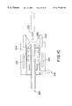
- FIG. 6 is a schematic diagram showing an alternative arrangement of the vortex gas flow interface of FIG. 3 and an electrospray needle.
- FIG. 7 is a schematic diagram showing another alternative arrangement of the vortex gas flow interface of FIG. 3 and an electrospray needle.
- FIG. 8 is a schematic diagram showing still another arrangement of the vortex gas flow interface of FIG. 3 and an electrospray needle.
- FIG. 9 is a schematic diagram showing a different embodiment of the vortex gas flow interface for electrospray mass spectrometry of the present invention.
- FIG. 10 is a schematic diagram showing yet another embodiment of the vortex gas flow interface for electrospray mass spectrometry of the present invention.
- FIG. 11 is a schematic diagram showing an embodiment of the present invention which incorporates a sampling orifice and skimmer cone.
- FIG. 12 is a schematic diagram showing an embodiment of the apparatus of FIG. 11 which incorporates a conical sampling orifice.
- the present invention is directed to an apparatus for facilitating the use of a liquid chromatograph (LC) with a vacuum instrument such as a mass spectrometer (MS), and is described in connection with an interface placed between the input port of a mass spectrometer and the output of an electrospray needle used to form charged drops of a liquid sample matrix.
- the interface of the present invention forms a vortex gas flow which intersects the flow of charged drops from the electrospray needle, with the vortex flow direction oriented substantially transverse to the droplet flow direction.
- the vortex gas flow separates the larger drops from the smaller ones by imparting a centrifugal force to the drops.
- the present invention provides several advantages over prior art methods of reducing the number of large drops injected by electrospray into a mass spectrometer, including: (1) improved separation of undesired large drops from smaller drops; (2) improved removal of carrier liquid(s) from charged drops, thereby preventing the formation of salt deposits at the capillary entrance to the mass spectrometer; (3) improved transport of charged sample ions into the mass spectrometer by enhancing the pressure gradient between the entrance to the spectrometer and the surrounding region where the electrosprayed drops reside; and (4) improved transport of charged sample ions into the mass spectrometer by providing an insulating vortex drying tube which confines the charged drops in the radial direction as they move towards the entrance to the spectrometer.
- FIG. 3 is a schematic diagram showing a first embodiment of the present invention, showing the vortex gas flow interface 200 for electrospray injection into a mass spectrometer.
- a central capillary tube 210 (or in the alternative an orifice or skimmer cone) connects a region held at low pressure by a vacuum system and containing the mass spectrometer 209 , with a region at substantially atmospheric pressure in which ions are produced by electrospray needle 212 .
- a drying gas flows through a plurality of vortex forming channels 214 disposed about the longitudinal axis of central capillary tube 210 .
- the drying gas is heated for improved drying efficiency.
- the gas 218 may be heated by heating element 216 in the flow path of drying gas 218 .
- Vortex forming gas channels 214 can be made by machining interleaved multi-start threads or channels into a metal insert, and press fitting the insert into a metal retaining structure (such as element 220 of the figure).
- the channels may be of any selected cross-section.
- central capillary tube 210 extends through the center of the vortex forming insert.
- heating elements 216 in retaining structure 220 act to heat the end of central capillary 210 and drying gas 218 as it enters the vortex forming structure.
- Gas exiting vortex forming channels 214 enters tangentially to the inside of vortex drying tube 222 and with a small helix angle, causing the gas to swirl around the tube, forming a vortex gas flow.
- the channels form helical threads which extend the entire length of the insert. Each channel has an inlet and an outlet.
- the swirling flow of the drying gas encounters the electrospray ejected from needle 212 in vortex drying tube 222 .
- the vortex gas flow acts to separate undesired large drops from smaller drops in the electrospray by imparting a rotational motion, and hence centrifugal force to the drops. This causes the largest drops to be driven into the wall of drying tube 222 where some of them are fragmented into smaller drops by a combination of evaporation and collision with the wall.
- the region of the vortex flow closer to central capillary 210 is at a pressure that is substantially below the pressure near the walls of drying tube 222 . This is primarily the result of two effects: (1) the radial pressure gradient formed by the vortex; and (2) the vacuum from the central capillary tube.
- An electrospray needle 212 with a gas nebulizer may be used to create the charged drops that are sprayed into vortex gas flow interface 200 .
- the gas nebulizer can be of the multi-capillary tube type disclosed in the U.S. patent application Ser. No. 09/162,261 entitled, “Pneumatically Assisted Electrospray Device with Alternating Pressure Gradients for Mass Spectrometry,” assigned to the same assignee and filed the same day as the present application, the contents of which are hereby incorporated by reference.
- the output of electrospray needle 212 is directed at an angle with respect to the axis of capillary tube 210 , with its output end directed towards the wall of vortex drying tube 222 where the vortex gas has its greatest velocity.
- FIG. 4 shows the output signal from an electrometer (with 0.2 millisecond time constant) of the ion current measured at the exit of the central capillary tube inside of the vacuum chamber for the prior art electrospray device shown in FIG. 1 .
- the data shown in FIG. 4 was obtained using a laminar counter flow of nitrogen of 4 liters/minute and a gas temperature of 100° C.
- FIG. 5 shows the signal from the electrometer for the vortex gas flow interface of the present invention shown in FIG. 3 under the same drying gas flow and temperature conditions as those used to obtain the data for FIG. 4 .
- the reduction in the peak-to-peak noise that is observed in FIG. 5 as compared to FIG. 4, along with only a small reduction in the average ion current, is an indication of the reduced droplet size achieved using the inventive vortex flow interface.
- FIG. 6 is a schematic diagram showing an alternative arrangement of the vortex gas flow interface of FIG. 3 and an electrospray needle.
- the axis of electrospray needle 212 is directed more towards the entrance of central capillary 210 instead of the wall of drying tube 222 , as for the embodiment of FIG. 3, but is still at an angle relative to the axis of tube 210 .
- FIG. 7 is a schematic diagram showing another alternative arrangement of the vortex gas flow interface of FIG. 3 and an electrospray needle.
- the axis of electrospray needle 212 is coaxial with the entrance of central capillary 210 .
- FIG. 8 is a schematic diagram showing still another arrangement of the vortex gas flow interface of FIG. 3 and an electrospray needle.
- the axis of electrospray needle 212 is displaced from the axis of the entrance to central capillary 210 , but parallel to it.
- FIG. 9 is a diagram showing a different embodiment of the vortex gas flow interface of the present invention.
- a sampling tip 230 has been added to central capillary tube 210 .
- Sampling tip 230 may be tapered at an angle as shown in the figure. It may also take the form of a thin walled extension of central tube 210 away from the vortex forming structure and further into the vortex flow in drying tube 222 , to optimize the pressure region in which the ions are sampled into the central capillary entrance.
- Sampling tip 230 is used to locate the entrance of capillary 210 in the optimal region of the vortex formed by the vortex forming channels. There is a stagnant region on the front surface of the vortex forming structure between the exit of the gas channels and the opening into the vacuum chamber (i.e. capillary exit, or aperture). It is possible that large droplets could enter this region and be sucked into the opening to the vacuum chamber. By extending the opening away from the front surface of the vortex forming structure, large droplets are forced to encounter the gas flow and are displaced from the opening.
- FIG. 10 is a diagram showing yet another embodiment of the vortex gas flow interface of the present invention.
- a flow shaping structure 232 has been added to vortex drying tube 222 so that the angular velocity of the gas is increased in the region in front of the entrance to capillary 210 .
- the flow shaping structure can be used to optimize the ion sampling process into the capillary entrance.
- FIGS. 11 and 12 are schematic diagrams showing an embodiment of the present invention which incorporates a sampling orifice 250 and skimmer cone 252 .
- FIG. 11 shows the use of a flat sampling orifice
- FIG. 12 shows the use of a conical sampling orifice to sample the ions from the vortex region into the first stage of the vacuum system. Gas traversing such small orifices, with a large pressure drop across them, undergoes a supersonic expansion. Skimmer cone 252 is often positioned down stream from the orifice and located within the silent zone, where the molecular motion is unidirectional.
- the gas jet that emerges from the other side of the skimmer, in which the sample ions are entrained, is directed towards the mass analyzer section of the mass spectrometer. Excess gas outside of the silent zone in the region up stream from the skimmer cone is typically removed by a vacuum pump through outlet 254 .
- the various embodiments of the present invention disclosed herein exemplify different ways of optimizing the performance of the interface.
- the parameters to be optimized are: (1) maximize the signal of interest; and (2) minimize the noise due to large charged droplets.
- the optimum conditions may be different due to the use of different flow rates and liquid compositions.
- Alternate embodiments for vortex drying tube 222 include: (1) making it of a conducting material; and (2) making the tube of a resistive material so that as charge accumulates along the surface of the tube from collisions with the charged drops, a potential difference is generated along the length of the tube due to the current flowing to ground. This will produce a potential gradient in a direction that drives the ions toward the central capillary aperture.
- Yet another embodiment could utilize a grounded needle and bias the vortex structure and the end of the central capillary tube at the appropriate voltage to induce electrospray ionization.
- drying tube material also involves optimizing the signal-to-noise ratio.
- High liquid flow rate and liquids that are susceptible to forming large droplets i.e. high aqueous content liquids
- the vortex forming structure can be made from a plurality of gas delivery tubes that are located on the end of, and tangent to, the drying tube. If the tubes are positioned with a helix angle similar to that of the multi-start threaded structure described herein, the resulting gas flow will form a vortex flow.
- the central capillary tube could be replaced or augmented by a skimmer cone or orifice in a flat plate.
- Novel features of the present invention include: (1) formation of a vortex drying gas flow, symmetrically disposed around and transverse to the axis of a central capillary tube entrance to a mass spectrometer, to impart a centrifugal force to the drops and separate out the large drops formed when using electrospray ionization for high sample liquid flow rates; (2) use of an electrically insulating vortex drying tube to confine charged drops in the radial direction as they move towards the inlet to the mass spectrometer; (3) improvement of the transport of charged sample into a mass spectrometer by enhancing the pressure gradient between the entrance to the mass spectrometer and the surrounding gas containing the electrosprayed drops; and (4) use of a capillary tube, skimmer cone, or orifice that extends into the low pressure region of the vortex flow to optimally sample the desolvated ions.
Landscapes
- Chemical & Material Sciences (AREA)
- Analytical Chemistry (AREA)
- Physics & Mathematics (AREA)
- Engineering & Computer Science (AREA)
- Plasma & Fusion (AREA)
- Electron Tubes For Measurement (AREA)
- Other Investigation Or Analysis Of Materials By Electrical Means (AREA)
- Sampling And Sample Adjustment (AREA)
Priority Applications (7)
| Application Number | Priority Date | Filing Date | Title |
|---|---|---|---|
| US09/162,258 US6177669B1 (en) | 1998-09-28 | 1998-09-28 | Vortex gas flow interface for electrospray mass spectrometry |
| CA002345683A CA2345683C (en) | 1998-09-28 | 1999-09-27 | Vortex gas flow interface for electrospray mass spectrometry |
| DE1118097T DE1118097T1 (de) | 1998-09-28 | 1999-09-27 | Gas-verwirbelungs-übergangsstück für die elektrospray massenspektrometrie |
| JP2000572894A JP4657451B2 (ja) | 1998-09-28 | 1999-09-27 | 電気スプレー質量分析のための渦状ガス流インターフェース |
| EP99954671A EP1118097B1 (en) | 1998-09-28 | 1999-09-27 | Vortex gas flow interface for electrospray mass spectrometry |
| PCT/US1999/022446 WO2000019484A1 (en) | 1998-09-28 | 1999-09-27 | Vortex gas flow interface for electrospray mass spectrometry |
| DE69934128T DE69934128T2 (de) | 1998-09-28 | 1999-09-27 | Gas-verwirbelungs-übergangsstück für die elektrospray massenspektrometrie |
Applications Claiming Priority (1)
| Application Number | Priority Date | Filing Date | Title |
|---|---|---|---|
| US09/162,258 US6177669B1 (en) | 1998-09-28 | 1998-09-28 | Vortex gas flow interface for electrospray mass spectrometry |
Publications (1)
| Publication Number | Publication Date |
|---|---|
| US6177669B1 true US6177669B1 (en) | 2001-01-23 |
Family
ID=22584860
Family Applications (1)
| Application Number | Title | Priority Date | Filing Date |
|---|---|---|---|
| US09/162,258 Expired - Lifetime US6177669B1 (en) | 1998-09-28 | 1998-09-28 | Vortex gas flow interface for electrospray mass spectrometry |
Country Status (6)
| Country | Link |
|---|---|
| US (1) | US6177669B1 (ja) |
| EP (1) | EP1118097B1 (ja) |
| JP (1) | JP4657451B2 (ja) |
| CA (1) | CA2345683C (ja) |
| DE (2) | DE1118097T1 (ja) |
| WO (1) | WO2000019484A1 (ja) |
Cited By (22)
| Publication number | Priority date | Publication date | Assignee | Title |
|---|---|---|---|---|
| US6455846B1 (en) * | 1999-10-14 | 2002-09-24 | Battelle Memorial Institute | Sample inlet tube for ion source |
| US6566652B1 (en) * | 1999-09-13 | 2003-05-20 | Hitachi, Ltd. | Mass spectrometry apparatus having ion source not at negative pressure when finishing measurement |
| US20030155506A1 (en) * | 2002-02-15 | 2003-08-21 | Motchkine Viatcheslav S. | Cyclone sampling nozzle for an ion mobility spectrometer |
| US20030189170A1 (en) * | 2002-04-09 | 2003-10-09 | Covey Thomas R. | Method of and apparatus for ionizing an analyte and ion source probe for use therewith |
| US20030189169A1 (en) * | 2002-04-04 | 2003-10-09 | Wells Gregory J. | Vortex flow atmospheric pressure chemical ionization source for mass spectrometry |
| GB2392775A (en) * | 2002-08-08 | 2004-03-10 | Bruker Daltonik Gmbh | Ionization at atmospheric pressure for mass spectrometric analysis |
| US20040094706A1 (en) * | 2001-04-09 | 2004-05-20 | Thomas Covey | Method of and apparatus for ionizing an analyte and ion source probe for use therewith |
| US20040155181A1 (en) * | 2002-02-15 | 2004-08-12 | Krasnobaev Leonid Ya. | Virtual wall gas sampling for an ion mobility spectrometer |
| US6781116B2 (en) | 2000-10-12 | 2004-08-24 | Micromass Uk Limited | Mass spectrometer |
| US20040217280A1 (en) * | 2003-02-14 | 2004-11-04 | Mds Sciex | Atmospheric pressure charged particle discriminator for mass spectrometry |
| US20060131497A1 (en) * | 2004-12-17 | 2006-06-22 | Varian, Inc. | Atmospheric pressure ionization with optimized drying gas flow |
| US20090045330A1 (en) * | 2007-08-15 | 2009-02-19 | Varian, Inc. | Sample ionization at above-vacuum pressures |
| US20100000943A1 (en) * | 2006-12-08 | 2010-01-07 | Carson William W | Method and apparatus for desolvating flowing liquid |
| US8227750B1 (en) * | 2008-04-28 | 2012-07-24 | Bruker-Michrom, Inc. | Method and apparatus for nano-capillary/micro electrospray for use in liquid chromatography-mass spectrometry |
| US20140284473A1 (en) * | 2011-10-17 | 2014-09-25 | Shimadzu Corporation | Atmospheric pressure ionization mass spectrometer |
| CN105185687A (zh) * | 2014-06-11 | 2015-12-23 | 布鲁克·道尔顿公司 | 在电喷雾电离中用于去除微粒物质的偏轴通道 |
| CN110112051A (zh) * | 2019-05-20 | 2019-08-09 | 中国科学院化学研究所 | 用于质谱反应加速和信号增强的涡流管及实现方法 |
| CN110364412A (zh) * | 2019-07-23 | 2019-10-22 | 中国科学院上海有机化学研究所 | 一种火焰辅助电喷雾离子化装置及使用该装置实现离子化的方法 |
| CN110603441A (zh) * | 2017-05-12 | 2019-12-20 | 胜高股份有限公司 | 喷雾室、试样雾化导入装置、分析装置和试样中的成分分析方法 |
| CN112117180A (zh) * | 2020-09-24 | 2020-12-22 | 中国核动力研究设计院 | 一种高凝固温度气态组分取样装置及取样方法 |
| CN113237981A (zh) * | 2021-03-31 | 2021-08-10 | 中国科学院化学研究所 | 一种用于活体微透析质谱联用实时在线分析技术的新型接口 |
| US11189477B2 (en) * | 2017-08-17 | 2021-11-30 | Dh Technologies Development Pte. Ltd. | APCI ion source with asymmetrical spray |
Families Citing this family (2)
| Publication number | Priority date | Publication date | Assignee | Title |
|---|---|---|---|---|
| GB0024981D0 (en) * | 2000-10-12 | 2000-11-29 | Micromass Ltd | Method and apparatus for mass spectrometry |
| GB2378572B (en) * | 2000-10-12 | 2003-07-16 | Micromass Ltd | Mass spectrometer |
Citations (7)
| Publication number | Priority date | Publication date | Assignee | Title |
|---|---|---|---|---|
| US4531056A (en) | 1983-04-20 | 1985-07-23 | Yale University | Method and apparatus for the mass spectrometric analysis of solutions |
| US4861988A (en) | 1987-09-30 | 1989-08-29 | Cornell Research Foundation, Inc. | Ion spray apparatus and method |
| US4885076A (en) | 1987-04-06 | 1989-12-05 | Battelle Memorial Institute | Combined electrophoresis-electrospray interface and method |
| US5157260A (en) | 1991-05-17 | 1992-10-20 | Finnian Corporation | Method and apparatus for focusing ions in viscous flow jet expansion region of an electrospray apparatus |
| US5412208A (en) * | 1994-01-13 | 1995-05-02 | Mds Health Group Limited | Ion spray with intersecting flow |
| EP0715337A1 (en) | 1994-11-28 | 1996-06-05 | Hitachi, Ltd. | Mass spectrometry of solution and apparatus therefor |
| US5581081A (en) * | 1993-12-09 | 1996-12-03 | Hitachi, Ltd. | Method and apparatus for direct coupling of liquid chromatograph and mass spectrometer, liquid chromatograph-mass spectrometry, and liquid chromatograph mass spectrometer |
Family Cites Families (2)
| Publication number | Priority date | Publication date | Assignee | Title |
|---|---|---|---|---|
| JPH10125275A (ja) * | 1996-10-23 | 1998-05-15 | Hitachi Ltd | 大気圧イオン化質量分析計 |
| JP2882402B2 (ja) * | 1997-10-24 | 1999-04-12 | 株式会社日立製作所 | 質量分析の方法および装置 |
-
1998
- 1998-09-28 US US09/162,258 patent/US6177669B1/en not_active Expired - Lifetime
-
1999
- 1999-09-27 DE DE1118097T patent/DE1118097T1/de active Pending
- 1999-09-27 CA CA002345683A patent/CA2345683C/en not_active Expired - Fee Related
- 1999-09-27 JP JP2000572894A patent/JP4657451B2/ja not_active Expired - Lifetime
- 1999-09-27 WO PCT/US1999/022446 patent/WO2000019484A1/en active IP Right Grant
- 1999-09-27 EP EP99954671A patent/EP1118097B1/en not_active Expired - Lifetime
- 1999-09-27 DE DE69934128T patent/DE69934128T2/de not_active Expired - Lifetime
Patent Citations (7)
| Publication number | Priority date | Publication date | Assignee | Title |
|---|---|---|---|---|
| US4531056A (en) | 1983-04-20 | 1985-07-23 | Yale University | Method and apparatus for the mass spectrometric analysis of solutions |
| US4885076A (en) | 1987-04-06 | 1989-12-05 | Battelle Memorial Institute | Combined electrophoresis-electrospray interface and method |
| US4861988A (en) | 1987-09-30 | 1989-08-29 | Cornell Research Foundation, Inc. | Ion spray apparatus and method |
| US5157260A (en) | 1991-05-17 | 1992-10-20 | Finnian Corporation | Method and apparatus for focusing ions in viscous flow jet expansion region of an electrospray apparatus |
| US5581081A (en) * | 1993-12-09 | 1996-12-03 | Hitachi, Ltd. | Method and apparatus for direct coupling of liquid chromatograph and mass spectrometer, liquid chromatograph-mass spectrometry, and liquid chromatograph mass spectrometer |
| US5412208A (en) * | 1994-01-13 | 1995-05-02 | Mds Health Group Limited | Ion spray with intersecting flow |
| EP0715337A1 (en) | 1994-11-28 | 1996-06-05 | Hitachi, Ltd. | Mass spectrometry of solution and apparatus therefor |
Cited By (45)
| Publication number | Priority date | Publication date | Assignee | Title |
|---|---|---|---|---|
| US6566652B1 (en) * | 1999-09-13 | 2003-05-20 | Hitachi, Ltd. | Mass spectrometry apparatus having ion source not at negative pressure when finishing measurement |
| US6455846B1 (en) * | 1999-10-14 | 2002-09-24 | Battelle Memorial Institute | Sample inlet tube for ion source |
| US6781116B2 (en) | 2000-10-12 | 2004-08-24 | Micromass Uk Limited | Mass spectrometer |
| US20040094706A1 (en) * | 2001-04-09 | 2004-05-20 | Thomas Covey | Method of and apparatus for ionizing an analyte and ion source probe for use therewith |
| US20040155181A1 (en) * | 2002-02-15 | 2004-08-12 | Krasnobaev Leonid Ya. | Virtual wall gas sampling for an ion mobility spectrometer |
| US20030155506A1 (en) * | 2002-02-15 | 2003-08-21 | Motchkine Viatcheslav S. | Cyclone sampling nozzle for an ion mobility spectrometer |
| US6888128B2 (en) * | 2002-02-15 | 2005-05-03 | Implant Sciences Corporation | Virtual wall gas sampling for an ion mobility spectrometer |
| US6861646B2 (en) * | 2002-02-15 | 2005-03-01 | Implant Sciences Corporation | Cyclone sampling nozzle for an ion mobility spectrometer |
| US20030189169A1 (en) * | 2002-04-04 | 2003-10-09 | Wells Gregory J. | Vortex flow atmospheric pressure chemical ionization source for mass spectrometry |
| WO2003085694A1 (en) | 2002-04-04 | 2003-10-16 | Varian, Inc. | Vortex flow atmospheric pressure chemical ionization source for mass spectrometry |
| US6818888B2 (en) * | 2002-04-04 | 2004-11-16 | Varian, Inc. | Vortex flow atmospheric pressure chemical ionization source for mass spectrometry |
| US6759650B2 (en) * | 2002-04-09 | 2004-07-06 | Mds Inc. | Method of and apparatus for ionizing an analyte and ion source probe for use therewith |
| US20030189170A1 (en) * | 2002-04-09 | 2003-10-09 | Covey Thomas R. | Method of and apparatus for ionizing an analyte and ion source probe for use therewith |
| US20040129876A1 (en) * | 2002-08-08 | 2004-07-08 | Bruker Daltonik Gmbh | Ionization at atomspheric pressure for mass spectrometric analyses |
| GB2392775A (en) * | 2002-08-08 | 2004-03-10 | Bruker Daltonik Gmbh | Ionization at atmospheric pressure for mass spectrometric analysis |
| GB2392775B (en) * | 2002-08-08 | 2006-03-29 | Bruker Daltonik Gmbh | Ionization at atmospheric pressure for mass spectrometric analyses |
| GB2392775A9 (en) * | 2002-08-08 | 2005-07-12 | Bruker Daltonik Gmbh | Ionization at atmospheric pressure for mass spectrometric analysis |
| US6949739B2 (en) | 2002-08-08 | 2005-09-27 | Brunker Daltonik Gmbh | Ionization at atmospheric pressure for mass spectrometric analyses |
| US20060226354A1 (en) * | 2003-02-14 | 2006-10-12 | Mds Sciex | Atmospheric pressure charged particle discriminator for mass spectrometry |
| US7462826B2 (en) | 2003-02-14 | 2008-12-09 | Mds Sciex | Atmospheric pressure charged particle discriminator for mass spectrometry |
| US20060118715A1 (en) * | 2003-02-14 | 2006-06-08 | Mds Sciex | Atmospheric pressure charged particle discriminator for mass spectrometry |
| US7098452B2 (en) * | 2003-02-14 | 2006-08-29 | Mds Sciex | Atmospheric pressure charged particle discriminator for mass spectrometry |
| US20040217280A1 (en) * | 2003-02-14 | 2004-11-04 | Mds Sciex | Atmospheric pressure charged particle discriminator for mass spectrometry |
| US7145136B2 (en) | 2004-12-17 | 2006-12-05 | Varian, Inc. | Atmospheric pressure ionization with optimized drying gas flow |
| WO2006065520A3 (en) * | 2004-12-17 | 2007-05-24 | Varian Inc | Atmospheric pressure ionization with optimized drying gas flow |
| US20060131497A1 (en) * | 2004-12-17 | 2006-06-22 | Varian, Inc. | Atmospheric pressure ionization with optimized drying gas flow |
| US8920658B2 (en) | 2006-12-08 | 2014-12-30 | Spectra Analysis Instruments, Inc. | Method and apparatus for desolvating flowing liquid |
| US20100000943A1 (en) * | 2006-12-08 | 2010-01-07 | Carson William W | Method and apparatus for desolvating flowing liquid |
| US8695813B2 (en) * | 2006-12-08 | 2014-04-15 | Spectra Analysis Instruments, Incorporated | Method and apparatus for desolvating flowing liquid |
| US20090045330A1 (en) * | 2007-08-15 | 2009-02-19 | Varian, Inc. | Sample ionization at above-vacuum pressures |
| US7564029B2 (en) | 2007-08-15 | 2009-07-21 | Varian, Inc. | Sample ionization at above-vacuum pressures |
| US8227750B1 (en) * | 2008-04-28 | 2012-07-24 | Bruker-Michrom, Inc. | Method and apparatus for nano-capillary/micro electrospray for use in liquid chromatography-mass spectrometry |
| US20140284473A1 (en) * | 2011-10-17 | 2014-09-25 | Shimadzu Corporation | Atmospheric pressure ionization mass spectrometer |
| US9040902B2 (en) * | 2011-10-17 | 2015-05-26 | Shimadzu Corporation | Atmospheric pressure ionization mass spectrometer |
| CN105185687A (zh) * | 2014-06-11 | 2015-12-23 | 布鲁克·道尔顿公司 | 在电喷雾电离中用于去除微粒物质的偏轴通道 |
| US9230786B1 (en) * | 2014-06-11 | 2016-01-05 | Bruker Daltonics, Inc. | Off-axis channel in electrospray ionization for removal of particulate matter |
| CN105185687B (zh) * | 2014-06-11 | 2018-10-09 | 布鲁克·道尔顿公司 | 在电喷雾电离中用于去除微粒物质的偏轴通道 |
| CN110603441A (zh) * | 2017-05-12 | 2019-12-20 | 胜高股份有限公司 | 喷雾室、试样雾化导入装置、分析装置和试样中的成分分析方法 |
| US11648574B2 (en) * | 2017-05-12 | 2023-05-16 | Sumco Corporation | Spray chamber, sample atomization and introduction device, analysis device, and method of analyzing component in sample |
| US11189477B2 (en) * | 2017-08-17 | 2021-11-30 | Dh Technologies Development Pte. Ltd. | APCI ion source with asymmetrical spray |
| CN110112051A (zh) * | 2019-05-20 | 2019-08-09 | 中国科学院化学研究所 | 用于质谱反应加速和信号增强的涡流管及实现方法 |
| CN110364412A (zh) * | 2019-07-23 | 2019-10-22 | 中国科学院上海有机化学研究所 | 一种火焰辅助电喷雾离子化装置及使用该装置实现离子化的方法 |
| CN112117180A (zh) * | 2020-09-24 | 2020-12-22 | 中国核动力研究设计院 | 一种高凝固温度气态组分取样装置及取样方法 |
| CN112117180B (zh) * | 2020-09-24 | 2022-03-01 | 中国核动力研究设计院 | 一种高凝固温度气态组分取样装置及取样方法 |
| CN113237981A (zh) * | 2021-03-31 | 2021-08-10 | 中国科学院化学研究所 | 一种用于活体微透析质谱联用实时在线分析技术的新型接口 |
Also Published As
| Publication number | Publication date |
|---|---|
| EP1118097B1 (en) | 2006-11-22 |
| DE69934128D1 (de) | 2007-01-04 |
| JP4657451B2 (ja) | 2011-03-23 |
| CA2345683A1 (en) | 2000-04-06 |
| JP2002526892A (ja) | 2002-08-20 |
| WO2000019484A1 (en) | 2000-04-06 |
| DE69934128T2 (de) | 2007-09-20 |
| DE1118097T1 (de) | 2001-12-20 |
| CA2345683C (en) | 2004-05-25 |
| EP1118097A1 (en) | 2001-07-25 |
Similar Documents
| Publication | Publication Date | Title |
|---|---|---|
| US6177669B1 (en) | Vortex gas flow interface for electrospray mass spectrometry | |
| JP3079055B2 (ja) | エレクトロスプレー、大気圧化学的イオン化質量分析計およびイオン発生源 | |
| US4999493A (en) | Electrospray ionization interface and method for mass spectrometry | |
| US5223226A (en) | Insulated needle for forming an electrospray | |
| US5245186A (en) | Electrospray ion source for mass spectrometry | |
| EP0644796B1 (en) | Atmospheric pressure ion interface for a mass analyzer | |
| JP3993895B2 (ja) | 質量分光測定装置及びイオン輸送分析方法 | |
| US8546750B2 (en) | Mass spectrometer interface | |
| JP5073168B2 (ja) | 質量分析計用の高速組合せマルチモードイオン源 | |
| US8227750B1 (en) | Method and apparatus for nano-capillary/micro electrospray for use in liquid chromatography-mass spectrometry | |
| EP0161744B1 (en) | Mass spectrometer | |
| US5304798A (en) | Housing for converting an electrospray to an ion stream | |
| US6207955B1 (en) | Pneumatically assisted electrospray device with alternating pressure gradients for mass spectrometry | |
| US20030062474A1 (en) | Electrospray ion source for mass spectrometry with atmospheric pressure desolvating capabilities | |
| US7417226B2 (en) | Mass spectrometer | |
| US20110039350A1 (en) | High yield atmospheric pressure ion source for ion spectrometers in vacuum | |
| US8680460B2 (en) | Converging-diverging supersonic shock disruptor for fluid nebulization and drop fragmentation | |
| JP3379989B2 (ja) | 電気噴霧をイオン流に変換するためのハウジング | |
| US9589782B2 (en) | Charged droplets generating apparatus including a gas conduit for laminarization of gas flows | |
| WO2000019193A1 (en) | Split flow electrospray device for mass spectrometry | |
| US8502162B2 (en) | Atmospheric pressure ionization apparatus and method | |
| JP2005135897A (ja) | 質量分析計 |
Legal Events
| Date | Code | Title | Description |
|---|---|---|---|
| AS | Assignment |
Owner name: VARIAN ASSOCIATES, INC., CALIFORNIA Free format text: ASSIGNMENT OF ASSIGNORS INTEREST;ASSIGNORS:WELLS, GREGORY J.;TONG, ROGER C.;YEE, PETER P.;REEL/FRAME:009493/0409 Effective date: 19980922 |
|
| AS | Assignment |
Owner name: VARIAN, INC., CALIFORNIA Free format text: ASSIGNMENT OF ASSIGNORS INTEREST;ASSIGNOR:VARIAN ASSOCIATES, INC.;REEL/FRAME:009877/0977 Effective date: 19990406 |
|
| STCF | Information on status: patent grant |
Free format text: PATENTED CASE |
|
| FEPP | Fee payment procedure |
Free format text: PAYOR NUMBER ASSIGNED (ORIGINAL EVENT CODE: ASPN); ENTITY STATUS OF PATENT OWNER: LARGE ENTITY |
|
| FPAY | Fee payment |
Year of fee payment: 4 |
|
| FPAY | Fee payment |
Year of fee payment: 8 |
|
| AS | Assignment |
Owner name: AGILENT TECHNOLOGIES, INC., CALIFORNIA Free format text: ASSIGNMENT OF ASSIGNORS INTEREST;ASSIGNOR:VARIAN, INC.;REEL/FRAME:025368/0230 Effective date: 20101029 |
|
| FPAY | Fee payment |
Year of fee payment: 12 |