US6158926A - Suction system for urban wastes and for recyclable materials - Google Patents
Suction system for urban wastes and for recyclable materials Download PDFInfo
- Publication number
- US6158926A US6158926A US09/126,043 US12604398A US6158926A US 6158926 A US6158926 A US 6158926A US 12604398 A US12604398 A US 12604398A US 6158926 A US6158926 A US 6158926A
- Authority
- US
- United States
- Prior art keywords
- recyclable materials
- transport means
- turret
- opening
- sucking tube
- Prior art date
- Legal status (The legal status is an assumption and is not a legal conclusion. Google has not performed a legal analysis and makes no representation as to the accuracy of the status listed.)
- Expired - Fee Related
Links
Images


Classifications
-
- B—PERFORMING OPERATIONS; TRANSPORTING
- B65—CONVEYING; PACKING; STORING; HANDLING THIN OR FILAMENTARY MATERIAL
- B65F—GATHERING OR REMOVAL OF DOMESTIC OR LIKE REFUSE
- B65F3/00—Vehicles particularly adapted for collecting refuse
- B65F3/14—Vehicles particularly adapted for collecting refuse with devices for charging, distributing or compressing refuse in the interior of the tank of a refuse vehicle
- B65F3/20—Vehicles particularly adapted for collecting refuse with devices for charging, distributing or compressing refuse in the interior of the tank of a refuse vehicle with charging pistons, plates, or the like
- B65F3/201—Vehicles particularly adapted for collecting refuse with devices for charging, distributing or compressing refuse in the interior of the tank of a refuse vehicle with charging pistons, plates, or the like the charging pistons, plates or the like moving rectilinearly
-
- B—PERFORMING OPERATIONS; TRANSPORTING
- B65—CONVEYING; PACKING; STORING; HANDLING THIN OR FILAMENTARY MATERIAL
- B65F—GATHERING OR REMOVAL OF DOMESTIC OR LIKE REFUSE
- B65F1/00—Refuse receptacles; Accessories therefor
- B65F1/12—Refuse receptacles; Accessories therefor with devices facilitating emptying
- B65F1/127—Refuse receptacles; Accessories therefor with devices facilitating emptying by suction
-
- B—PERFORMING OPERATIONS; TRANSPORTING
- B65—CONVEYING; PACKING; STORING; HANDLING THIN OR FILAMENTARY MATERIAL
- B65F—GATHERING OR REMOVAL OF DOMESTIC OR LIKE REFUSE
- B65F1/00—Refuse receptacles; Accessories therefor
- B65F1/14—Other constructional features; Accessories
- B65F1/1426—Housings, cabinets or enclosures for refuse receptacles
- B65F1/1447—Housings, cabinets or enclosures for refuse receptacles located underground
-
- B—PERFORMING OPERATIONS; TRANSPORTING
- B65—CONVEYING; PACKING; STORING; HANDLING THIN OR FILAMENTARY MATERIAL
- B65F—GATHERING OR REMOVAL OF DOMESTIC OR LIKE REFUSE
- B65F3/00—Vehicles particularly adapted for collecting refuse
- B65F3/02—Vehicles particularly adapted for collecting refuse with means for discharging refuse receptacles thereinto
- B65F3/0206—Vehicles particularly adapted for collecting refuse with means for discharging refuse receptacles thereinto while the receptacles remain in place or are still attached to their supporting means
- B65F3/0209—Vehicles particularly adapted for collecting refuse with means for discharging refuse receptacles thereinto while the receptacles remain in place or are still attached to their supporting means using suction
-
- B—PERFORMING OPERATIONS; TRANSPORTING
- B65—CONVEYING; PACKING; STORING; HANDLING THIN OR FILAMENTARY MATERIAL
- B65F—GATHERING OR REMOVAL OF DOMESTIC OR LIKE REFUSE
- B65F2210/00—Equipment of refuse receptacles
- B65F2210/184—Weighing means
Definitions
- the present invention relates to a suction system for urban wastes and for recyclable materials.
- This collection system requires the use of these dumpsters which are not very aesthetic nor hygienic when placed in the streets.
- these dumpsters have swinging covers which can be damaged by the users and mostly by the collection means, i.e. by the special trucks used to collect the urban wastes. Besides, when the dumpsters are picked up and overturned, they may accidentally fall with consequent breaks and significant repair costs.
- the dumpsters due to their structure and to their content, make a lot of noise which disturbs the neighbourhoods since said operation is preferably done during the early morning hours.
- the dumpsters have also to be subjected to maintenance and to washing and sanitizing, which is a further complication due to their structure.
- a purpose of the present invention is to manufacture a waste collection system different from the one carried out by the dumpsters and by the relative trucks.
- Another purpose is to solve all the above mentioned problems related to the dumpsters.
- a suction system for urban wastes and for recyclable materials comprising a motorized transport means capable of receiving urban wastes and/or recyclable materials placed in a container, characterised in that said transport means is provided with a sucking tube which can be moved and which can be inserted, by means of actuators, inside an opening formed in an underground container, and closing means are provided for the opening, said means being provided with an opening of predetermined size.
- a suction system for urban wastes and/or for recyclable materials comprises a motorized transport means capable of receiving urban wastes and/or recyclable materials left on the ground, wherein said transport means is provided with a sucking tube which can be moved in order to suck said urban wastes and/or recyclable materials placed on the ground.
- FIG. 1 is a schematic perspective view of the suction system for urban wastes and for recyclable materials according to the present invention
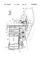
- FIG. 2 is an elevation view of the rear portion, in partial section, of the view of FIG. 1,
- FIG. 3 is a side elevation view in the direction of arrow F in FIG. 2,
- FIG. 4 is an enlarged view of a schematic detail, in partial section, from FIG. 2,
- FIG. 5 is a plan view of the detail of FIG. 4,
- FIG. 6 is an enlarged sectional view of the detail of the end of the extendable tube used to collect the wastes
- FIG. 7 is a schematic perspective view of a further embodiment of the suction system for urban wastes according to the invention.
- the system of the invention comprises a motorised transport means, as for instance a truck 10, formed substantially by a body 11, provided with a rear wall 12 which can be opened by means of specific actuators, as for instance cylinders 13.
- the truck 10 has, in its top inner portion, a turbine, indicated by numeral 14, connected, on one side, to the sucking tube and, on the other side, said turbine is open towards the inside portion of the truck body 11.
- a filter 16 is placed above the turbine 14, said filter allowing the air inside the truck body 11 to leave the truck 10 after proper filtration.
- the sucking tube comprises, in the area positioned above the truck 10, a fixed portion 15 facing one side of the truck 10, and said portion being connected to a curved portion 17 and to a vertical portion 18, both movable from the side wall of the truck.
- said curved portion 17 and said vertical portion 18 are placed on a supporting structure 19 which is driven by a cylinder 20 and slides along the supporting guides 21.
- Sealing elements 21 are positioned between the curved portion 17 and the fixed portion 15 of the sucking tube, said sealing elements allowing to maintain sealed conditions during the movement of the curved portion 17 in regard to the fixed portion 15 of the sucking tube.
- At least a further portion 23 of the tube is positioned at the lower end of the vertical portion 18, said portion can slide inside the vertical portion 18 and it is, for instance, of the telescopic type.
- the movement of the additional portion 23 of tube is driven by cylinders 25, a stem 24 and a cylinder 25 thereof are shown, said stem and said cylinder being vertically positioned and integral with the supporting structure 19.
- the supporting structure 19 has a shaped drive and containment arm 26 suitable to lean on a turret 27, said turret can slide along a fixed supporting base 28.
- Said turret 27 forms closing means provided with an opening 35 having a predefined dimension, said closing means can be freely moved with respect to an opening 34 of an underground container 36, and said fixed supporting base 28 being integral therewith.
- the system further comprises an underground container 36 formed by a shaped container placed in a hole excavated in the ground.
- the underground container 36 has a top container cover 29 wherein an opening 30 is formed.
- the opening 30 is usually positioned below the supporting base 28 which is integral with the cover 29 of the container.
- two side guides 31 are formed on the supporting base 28, as well as a wall 32 transverse thereto.
- This transverse wall 32 engages the cylinders 33, which cause, even automatically, the turret 27 to return against the transverse wall 32, once the turret has been moved from its initial working position.
- the turret 27 has, for instance on its front surface, an openable door 34, associated with an opening 35 provided with a fixed and predetermined size. Once said openable door 34 has been partially removed, for instance by rotatation around its hinges, a sack, containing the urban wastes to be eliminated and to be positioned inside the undreground container 36, is introduced through said opening 35.
- a footboard 37 having a weighing surface 39, can be provided in front of the turret 27, below said weighing surface a load cell, not shown, being positioned. In this way, the footboard 37 can be used to weigh the sack containing the wastes or to weigh the person who is putting or has already put the sack into the turret 27.
- FIG. 1 it is shown how the lower end of the sliding portion of the tube 23 is simply open and ready to suck the material or the sacks placed inside the underground container 36 by means of the turbine 14. If necessary, as shown in FIG. 6, a rotating element 38, properly driven, can be placed at the lower end of the portion of tube 23, said rotating element grinding the material contained in the underground container 36 and facilitating the sucking operation and the passage through the various tube portions connected to the sucking turbine 14.
- a sucking system for urban wastes is very easy to use, as explained hereinafter.
- a user in order to eliminate a waste containing bag, goes close to the turret 27 placed in its initial working position, i.e. aligned with the opening 30 formed on the top of the underground container 36.
- the bag is thrown inside the below container 36 through said turret 27 having reduced dimensions, and positioned at street level.
- the footboard 37 provided with the relative load cell, allows to weigh, if required, the discharged material and simultaneously the person by means of the load cell.
- the discharged material (bags, plastic containers, aluminum, glass, etc.) does never enter in contact with the weighing system thus avoiding the system to be soiled and obstructed.
- the transport means 10 devoted to collect the wastes, arrives close to the turret 27, and said transport means is positioned on the side of said turret.
- the positioning is done so that the hold and guide arm 26, integral with the supporting structure 19, is aligned with the rear portion of the turret.
- the cylinder 20 is driven by an operator in order to cause the lateral movement of the supporting structure 19.
- the drive and containment arm 26 consequently engages the rear portion of the turret 27 thus causing the turret to slide along the guides 31 and freeing the opening 30.
- Said operation is controlled by the operator without leaving the driving place and thus the bag sucking operation is started by lowering, by means of the hydraulic cylinders 25, the telescopic sucking tube.
- the powerful turbine 14 by creating the vacuum inside the truck body 11, causes the bags to climb through the various sections 15, 17, 18, 23 of the sucking tube and then to fall inside said body.
- the bags can be sucked by the sucking opening as they are, shown in FIG. 1, or they can be first ground by the rotating element 38, as for instance a centrifugal grinding device, and then sucked.
- the operator drives the hydraulic cylinder 25 which lifts again the tube sucking sections and then the horizontal hydraulic cylinder 20.
- Said cylinder 20 causes the supporting structure 19 to go back close to the truck and therefore to let the turret 27 free to go back to its initial working position, ready to receive additional bags, by means of the cylinders 33.
- the sucking tube can be provided with a spray system capable, once the sucking operations are finished, of sanitizing the underground containers.
- This system for collecting the urban wastes and recyclable materials has significant advantages in comparison with the previous dumpster system.
- the waste bags are discharged into the containers placed below the street level and therefore said containers are of difficult access for the public.
- the waste containers since they are underground, keep the wastes, especially during the summer time, at low temperature thus allowing to collect the wastes at longer periods of time than the current ones.
- the traditional dumpsters are eliminated and substituted, at street level, by a turret with reduced dimensions, said turret allowing the access to the underground container realised in several sizes.
- the walls of the turret can advantageously be used for advertising.
- the same sucking truck is suitable to collect both the urban and the recycled wastes.
- the turbines are sound-proof and have a noise level of about 80 Db, thus eliminating any previous inconvenience.
- the waste collection operations will then be much less noisy than the current ones.
- the collection will be done every two-three days and the duration of the operation will be for sure less than the current one.
- the hole of access wherein the sucking tube is introduced, does never remain open, since, when the turret 27 is moved to the side, the sucking tube covers said hole.
- Some underground containers can be devoted to collect materials separately (plastics, aluminum, glass, etc) since the system is able to suck also these products. Since the underground container are very large, the collection may be done at long time intervals with a consequent cost saving.
- the sucking system for urban wastes and for recyclable materials of the invention simply comprises a motorized transport means 10 capable of receiving urban wastes and/or recyclable materials placed on the ground, wherein said transport means 10 being provided with a sucking tube 15, 17, 18, 23 which can be moved in order to suck the urban wastes and/or the recyclable materials simply placed on the ground.
- FIG. 7 shows a further embodiment, wherein equal elements have the same reference number.
- a truck 10 provided with the sucking tube as described in FIG. 1, has a hydraulic compacting system placed inside the body 11.
- a compacting plate 40 is provided in the body 11, wherein said plate is moved by an actuator, as for instance a cylinder 41 which interacts between said plate and a fixed portion of the body 11.
- an actuator as for instance a cylinder 41 which interacts between said plate and a fixed portion of the body 11.
- the bottom of the body 11 has openings or, more simply, it is made of a perforated plate 42 and a liquid collection tank 43 is placed below said perforated plate.
- the cylinder 41 which causes the compacting plate 40 to move, is acivated.
- the urban wastes are then compacted and the liquid, coming out through the perforated plate 42, is collected in the tank 43 below.
- said tank 43 shall be provided with a discharge valve or tap, not shown, through which said tank will be emptied.
- the vertical compacting plate slides towards the rear wall 12 of the body 11, but a horizontal compacting plate could be provided as well, wherein said horizontal plate moves towards the top or the bottom of the body 11, or in both directions toward the centre of the body.
Abstract
Description
Claims (13)
Applications Claiming Priority (2)
| Application Number | Priority Date | Filing Date | Title |
|---|---|---|---|
| ITMI98A1042 | 1998-05-13 | ||
| IT98MI001042A IT1299236B1 (en) | 1998-05-13 | 1998-05-13 | URBAN WASTE SUCTION SYSTEM AND RECYCLING MATERIAL |
Publications (1)
| Publication Number | Publication Date |
|---|---|
| US6158926A true US6158926A (en) | 2000-12-12 |
Family
ID=11380011
Family Applications (1)
| Application Number | Title | Priority Date | Filing Date |
|---|---|---|---|
| US09/126,043 Expired - Fee Related US6158926A (en) | 1998-05-13 | 1998-07-30 | Suction system for urban wastes and for recyclable materials |
Country Status (7)
| Country | Link |
|---|---|
| US (1) | US6158926A (en) |
| EP (1) | EP0957048B1 (en) |
| AT (1) | ATE237536T1 (en) |
| CA (1) | CA2244485A1 (en) |
| DE (1) | DE69813506T2 (en) |
| ES (1) | ES2196479T3 (en) |
| IT (1) | IT1299236B1 (en) |
Cited By (11)
| Publication number | Priority date | Publication date | Assignee | Title |
|---|---|---|---|---|
| US20020157212A1 (en) * | 2001-04-25 | 2002-10-31 | The Regents Of The University Of California | Telerobotic nozzle positioning system for an automated roadway debris vacuum vehicle |
| DE10326930A1 (en) * | 2003-06-16 | 2005-01-27 | Schmidt, Sven | Cylindrical refuse bin has underground section which can be connected to extension by flanges fastened together by square bolts |
| US20100215443A1 (en) * | 2007-09-18 | 2010-08-26 | Sundholm Goeran | Waste conveying system |
| US8147169B1 (en) * | 2009-05-20 | 2012-04-03 | Kvalheim Andrew M | Apparatus for extracting and delivering articles in amounts of uniform size |
| US20120308314A1 (en) * | 2010-02-12 | 2012-12-06 | Maricap Oy | Method and apparatus for handling material in a pneumatic materials handling system |
| US20130004249A1 (en) * | 2010-03-12 | 2013-01-03 | Maricap Oy | Method and apparatus in a pneumatic material conveying system, and a waste conveying system |
| US20130078042A1 (en) * | 2010-06-03 | 2013-03-28 | Maricap Oy | Method in a waste conveying system, a waste conveying system and a vacuum source for a waste conveying system |
| CN101855149B (en) * | 2007-11-08 | 2013-11-13 | 恩华特公司 | Waste collection and management |
| KR20150030746A (en) * | 2012-07-02 | 2015-03-20 | 마리캡 오이 | Method and apparatus for handling material in a pneumatic materials handling system |
| US9555980B2 (en) * | 2013-11-22 | 2017-01-31 | Ag Growth Industries Partnership | Inlet for particulate loader |
| US11358785B2 (en) * | 2018-04-04 | 2022-06-14 | Superior Bulk, Inc. | Silo system and bulk material management system |
Families Citing this family (8)
| Publication number | Priority date | Publication date | Assignee | Title |
|---|---|---|---|---|
| NL1028337C2 (en) * | 2005-02-18 | 2006-08-21 | Rutte Beheer B V | Refuse container emptying device with pneumatic pump, has pair of drums at inlet end of suction tube for comminuting refuse in bin bags |
| DE102006037121A1 (en) * | 2006-08-09 | 2008-02-14 | Alfons Braun | Waste collection vehicle, e.g. for domestic waste, uses suction device for receiving waste from collection vehicle for transfer to collection container |
| DE102008027538A1 (en) * | 2008-06-10 | 2009-12-31 | Berthold Aicheler | Method and device for emptying waste containers |
| FR2964675B1 (en) | 2010-09-13 | 2013-06-28 | Sogreah Consultants | MOBILE WASTE COLLECTION UNIT, AND METHOD FOR IMPLEMENTING SUCH UNIT |
| DE102012108521A1 (en) * | 2012-09-12 | 2014-03-13 | Alfons Braun | Angular or round-shaped waste collection container for use in waste disposal system that is utilized for disposing urban domestic waste, has aperture formed in partial section, where spout of vehicle is inserted into hopper through aperture |
| CN103832756B (en) * | 2014-02-20 | 2016-09-28 | 白景魁 | The collection way of transportation of a kind of broad sense rubbish and equipment |
| CN111891587B (en) * | 2020-08-26 | 2022-11-04 | 四川卓锦未来环保科技有限公司 | Classified throwing method and device for household garbage |
| ES2950423A1 (en) * | 2022-03-06 | 2023-10-09 | Liberdade De Movimientos Unipessoal Lda | Waste collection system (Machine-translation by Google Translate, not legally binding) |
Citations (11)
| Publication number | Priority date | Publication date | Assignee | Title |
|---|---|---|---|---|
| US2002993A (en) * | 1934-07-26 | 1935-05-28 | Marion Steel Body Company | Refuse-collection device |
| US3348258A (en) * | 1965-06-18 | 1967-10-24 | Central Engineering Company In | Vacuum-type debris collector |
| US3613915A (en) * | 1969-11-07 | 1971-10-19 | Lawrence Vita | Garbage collection system |
| US3995754A (en) * | 1974-02-27 | 1976-12-07 | Lawrence Peska Associates, Inc. | Garbage vacuum compactor device |
| US4019219A (en) * | 1975-10-03 | 1977-04-26 | The Raymond Lee Organization, Inc. | Trash compactor apparatus |
| US4232632A (en) * | 1976-10-04 | 1980-11-11 | K-B Engineering Co. | Live fowl conveying system |
| EP0220936A2 (en) * | 1985-10-22 | 1987-05-06 | Raymond Neils Johnson | Materials processing unit |
| JPH0197203A (en) * | 1987-09-14 | 1989-04-14 | Dive N Surf | Wet suits |
| EP0408820A1 (en) * | 1989-05-17 | 1991-01-23 | Govoni Spa | Differentiated collecting station for used plastic containers with suction drawing |
| DE4331191A1 (en) * | 1993-09-14 | 1995-03-16 | Josef Soellner | Motor vehicle for the transportation of solid material collected in collection containers |
| FR2728879A1 (en) * | 1994-12-08 | 1996-07-05 | Decaux Jean Claude | Procedure for disposal and recycling of empty glass e.g. glass bottles and jars |
-
1998
- 1998-05-13 IT IT98MI001042A patent/IT1299236B1/en active IP Right Grant
- 1998-07-30 US US09/126,043 patent/US6158926A/en not_active Expired - Fee Related
- 1998-08-01 ES ES98202602T patent/ES2196479T3/en not_active Expired - Lifetime
- 1998-08-01 EP EP98202602A patent/EP0957048B1/en not_active Expired - Lifetime
- 1998-08-01 DE DE69813506T patent/DE69813506T2/en not_active Expired - Fee Related
- 1998-08-01 AT AT98202602T patent/ATE237536T1/en not_active IP Right Cessation
- 1998-08-04 CA CA002244485A patent/CA2244485A1/en not_active Abandoned
Patent Citations (11)
| Publication number | Priority date | Publication date | Assignee | Title |
|---|---|---|---|---|
| US2002993A (en) * | 1934-07-26 | 1935-05-28 | Marion Steel Body Company | Refuse-collection device |
| US3348258A (en) * | 1965-06-18 | 1967-10-24 | Central Engineering Company In | Vacuum-type debris collector |
| US3613915A (en) * | 1969-11-07 | 1971-10-19 | Lawrence Vita | Garbage collection system |
| US3995754A (en) * | 1974-02-27 | 1976-12-07 | Lawrence Peska Associates, Inc. | Garbage vacuum compactor device |
| US4019219A (en) * | 1975-10-03 | 1977-04-26 | The Raymond Lee Organization, Inc. | Trash compactor apparatus |
| US4232632A (en) * | 1976-10-04 | 1980-11-11 | K-B Engineering Co. | Live fowl conveying system |
| EP0220936A2 (en) * | 1985-10-22 | 1987-05-06 | Raymond Neils Johnson | Materials processing unit |
| JPH0197203A (en) * | 1987-09-14 | 1989-04-14 | Dive N Surf | Wet suits |
| EP0408820A1 (en) * | 1989-05-17 | 1991-01-23 | Govoni Spa | Differentiated collecting station for used plastic containers with suction drawing |
| DE4331191A1 (en) * | 1993-09-14 | 1995-03-16 | Josef Soellner | Motor vehicle for the transportation of solid material collected in collection containers |
| FR2728879A1 (en) * | 1994-12-08 | 1996-07-05 | Decaux Jean Claude | Procedure for disposal and recycling of empty glass e.g. glass bottles and jars |
Cited By (20)
| Publication number | Priority date | Publication date | Assignee | Title |
|---|---|---|---|---|
| US6789291B2 (en) * | 2001-04-25 | 2004-09-14 | The Regents Of The University Of California | Telerobotic nozzle positioning system for an automated roadway debris vacuum vehicle |
| US20020157212A1 (en) * | 2001-04-25 | 2002-10-31 | The Regents Of The University Of California | Telerobotic nozzle positioning system for an automated roadway debris vacuum vehicle |
| DE10326930A1 (en) * | 2003-06-16 | 2005-01-27 | Schmidt, Sven | Cylindrical refuse bin has underground section which can be connected to extension by flanges fastened together by square bolts |
| US20100215443A1 (en) * | 2007-09-18 | 2010-08-26 | Sundholm Goeran | Waste conveying system |
| US8727671B2 (en) * | 2007-09-18 | 2014-05-20 | Maricap Oy | Waste conveying system |
| CN101855149B (en) * | 2007-11-08 | 2013-11-13 | 恩华特公司 | Waste collection and management |
| US20120177451A1 (en) * | 2009-05-20 | 2012-07-12 | Kvalheim Andrew M | Apparatus for extracting and delivering articles in amounts of uniform size |
| US8322951B2 (en) * | 2009-05-20 | 2012-12-04 | Kvalheim Andrew M | Apparatus for extracting and delivering articles in amounts of uniform size |
| US8147169B1 (en) * | 2009-05-20 | 2012-04-03 | Kvalheim Andrew M | Apparatus for extracting and delivering articles in amounts of uniform size |
| US9156612B2 (en) * | 2010-02-12 | 2015-10-13 | Maricap Oy | Method and apparatus for handling material in a pneumatic materials handling system |
| US20120308314A1 (en) * | 2010-02-12 | 2012-12-06 | Maricap Oy | Method and apparatus for handling material in a pneumatic materials handling system |
| US20130004249A1 (en) * | 2010-03-12 | 2013-01-03 | Maricap Oy | Method and apparatus in a pneumatic material conveying system, and a waste conveying system |
| US9546041B2 (en) * | 2010-03-12 | 2017-01-17 | Maricap Oy | Method and apparatus in a pneumatic material conveying system, and a waste conveying system |
| US20130078042A1 (en) * | 2010-06-03 | 2013-03-28 | Maricap Oy | Method in a waste conveying system, a waste conveying system and a vacuum source for a waste conveying system |
| KR20150030746A (en) * | 2012-07-02 | 2015-03-20 | 마리캡 오이 | Method and apparatus for handling material in a pneumatic materials handling system |
| US20150321844A1 (en) * | 2012-07-02 | 2015-11-12 | Maricap Oy | Method and apparatus for handling material in a pneumatic materials handling system |
| AU2013285337B2 (en) * | 2012-07-02 | 2018-07-26 | Maricap Oy | Method and apparatus for handling material in a pneumatic materials handling system |
| US9555980B2 (en) * | 2013-11-22 | 2017-01-31 | Ag Growth Industries Partnership | Inlet for particulate loader |
| AU2013276989B2 (en) * | 2013-11-22 | 2018-03-01 | Rem Enterprises Inc. | Inlet for particulate loader |
| US11358785B2 (en) * | 2018-04-04 | 2022-06-14 | Superior Bulk, Inc. | Silo system and bulk material management system |
Also Published As
| Publication number | Publication date |
|---|---|
| EP0957048A1 (en) | 1999-11-17 |
| EP0957048B1 (en) | 2003-04-16 |
| ATE237536T1 (en) | 2003-05-15 |
| ES2196479T3 (en) | 2003-12-16 |
| DE69813506T2 (en) | 2004-04-01 |
| CA2244485A1 (en) | 1999-11-13 |
| DE69813506D1 (en) | 2003-05-22 |
| IT1299236B1 (en) | 2000-02-29 |
| ITMI981042A1 (en) | 1999-11-13 |
Similar Documents
| Publication | Publication Date | Title |
|---|---|---|
| US6158926A (en) | Suction system for urban wastes and for recyclable materials | |
| EP0708039B1 (en) | Device for collecting refuse, as well as removal and transport means therefor | |
| US3613915A (en) | Garbage collection system | |
| WO2020087030A1 (en) | Trash storage and disposal system and method | |
| US20210122567A1 (en) | Trash Storage and Disposal System and Method | |
| JP4383967B2 (en) | Garbage storage device installed on the ground | |
| EP0876971A1 (en) | Device for underground waste collection | |
| US4117777A (en) | Refuse container, and refuse compacting and discharging device therefor | |
| JPH08244906A (en) | Refuse storage device | |
| US20060104782A1 (en) | Apparatus for collecting waste | |
| KR102349231B1 (en) | Garbage collection vechicle with improved loading means | |
| EP1074487B1 (en) | System for lifting a container from a seat embedded in the ground and discharging wastes from the container into a body situated on a vehicle | |
| KR102053585B1 (en) | food garbage collection device | |
| CN210084123U (en) | Deodorant garbage collection device | |
| KR200451116Y1 (en) | waste basket | |
| CN109335399A (en) | A kind of solar energy intelligent garbage compression box | |
| CN209209592U (en) | A kind of Intelligent Compression dustbin | |
| CN110817202B (en) | Dustbin | |
| CN211495483U (en) | Garbage can | |
| CN207209088U (en) | A kind of public garbage bin | |
| JPH03186501A (en) | Road trash collecting vehicle | |
| JPS5920561B2 (en) | Dust storage device | |
| CN111099212A (en) | Buried foot-operated opening dustbin | |
| KR950005806Y1 (en) | A tank of a refuse vehicle | |
| KR0112718Y1 (en) | Press type wastes container |
Legal Events
| Date | Code | Title | Description |
|---|---|---|---|
| AS | Assignment |
Owner name: CAPPELLOTTO S.P.A., ITALY Free format text: ASSIGNMENT OF ASSIGNORS INTEREST;ASSIGNOR:PRECETTI, MASSIMO;REEL/FRAME:009356/0138 Effective date: 19980728 Owner name: TERMOMECCANICA S.P.A., ITALY Free format text: ASSIGNMENT OF ASSIGNORS INTEREST;ASSIGNOR:PRECETTI, MASSIMO;REEL/FRAME:009356/0138 Effective date: 19980728 |
|
| AS | Assignment |
Owner name: TM. P. S.P.A. TERMOMECCANICA, ITALY Free format text: ASSIGNMENT OF ASSIGNORS INTEREST;ASSIGNOR:TERMOMECCANICA S.P.A.;REEL/FRAME:011354/0048 Effective date: 20001107 |
|
| AS | Assignment |
Owner name: AER SYSTEM SRL, ITALY Free format text: ASSIGNMENT OF ASSIGNORS INTEREST;ASSIGNORS:TERMOMECCANICA S.P.A.;PRECETTI, MASSIMO;CAPPELLOTO S.P.A.;REEL/FRAME:014146/0214 Effective date: 20030124 |
|
| FPAY | Fee payment |
Year of fee payment: 4 |
|
| REMI | Maintenance fee reminder mailed | ||
| LAPS | Lapse for failure to pay maintenance fees | ||
| STCH | Information on status: patent discontinuation |
Free format text: PATENT EXPIRED DUE TO NONPAYMENT OF MAINTENANCE FEES UNDER 37 CFR 1.362 |
|
| FP | Lapsed due to failure to pay maintenance fee |
Effective date: 20081212 |