US6147328A - Apparatus for the heat treatment of workpieces - Google Patents
Apparatus for the heat treatment of workpieces Download PDFInfo
- Publication number
- US6147328A US6147328A US09/178,290 US17829098A US6147328A US 6147328 A US6147328 A US 6147328A US 17829098 A US17829098 A US 17829098A US 6147328 A US6147328 A US 6147328A
- Authority
- US
- United States
- Prior art keywords
- workpieces
- chambers
- frame
- chamber
- conveyor
- Prior art date
- Legal status (The legal status is an assumption and is not a legal conclusion. Google has not performed a legal analysis and makes no representation as to the accuracy of the status listed.)
- Expired - Fee Related
Links
Images
Classifications
-
- F—MECHANICAL ENGINEERING; LIGHTING; HEATING; WEAPONS; BLASTING
- F27—FURNACES; KILNS; OVENS; RETORTS
- F27B—FURNACES, KILNS, OVENS, OR RETORTS IN GENERAL; OPEN SINTERING OR LIKE APPARATUS
- F27B9/00—Furnaces through which the charge is moved mechanically, e.g. of tunnel type; Similar furnaces in which the charge moves by gravity
- F27B9/06—Furnaces through which the charge is moved mechanically, e.g. of tunnel type; Similar furnaces in which the charge moves by gravity heated without contact between combustion gases and charge; electrically heated
- F27B9/10—Furnaces through which the charge is moved mechanically, e.g. of tunnel type; Similar furnaces in which the charge moves by gravity heated without contact between combustion gases and charge; electrically heated heated by hot air or gas
-
- C—CHEMISTRY; METALLURGY
- C21—METALLURGY OF IRON
- C21D—MODIFYING THE PHYSICAL STRUCTURE OF FERROUS METALS; GENERAL DEVICES FOR HEAT TREATMENT OF FERROUS OR NON-FERROUS METALS OR ALLOYS; MAKING METAL MALLEABLE, e.g. BY DECARBURISATION OR TEMPERING
- C21D9/00—Heat treatment, e.g. annealing, hardening, quenching or tempering, adapted for particular articles; Furnaces therefor
- C21D9/0006—Details, accessories not peculiar to any of the following furnaces
- C21D9/0025—Supports; Baskets; Containers; Covers
-
- C—CHEMISTRY; METALLURGY
- C21—METALLURGY OF IRON
- C21D—MODIFYING THE PHYSICAL STRUCTURE OF FERROUS METALS; GENERAL DEVICES FOR HEAT TREATMENT OF FERROUS OR NON-FERROUS METALS OR ALLOYS; MAKING METAL MALLEABLE, e.g. BY DECARBURISATION OR TEMPERING
- C21D9/00—Heat treatment, e.g. annealing, hardening, quenching or tempering, adapted for particular articles; Furnaces therefor
- C21D9/24—Heat treatment, e.g. annealing, hardening, quenching or tempering, adapted for particular articles; Furnaces therefor for saw blades
-
- F—MECHANICAL ENGINEERING; LIGHTING; HEATING; WEAPONS; BLASTING
- F27—FURNACES; KILNS; OVENS; RETORTS
- F27B—FURNACES, KILNS, OVENS, OR RETORTS IN GENERAL; OPEN SINTERING OR LIKE APPARATUS
- F27B9/00—Furnaces through which the charge is moved mechanically, e.g. of tunnel type; Similar furnaces in which the charge moves by gravity
- F27B9/02—Furnaces through which the charge is moved mechanically, e.g. of tunnel type; Similar furnaces in which the charge moves by gravity of multiple-track type; of multiple-chamber type; Combinations of furnaces
- F27B9/028—Multi-chamber type furnaces
-
- F—MECHANICAL ENGINEERING; LIGHTING; HEATING; WEAPONS; BLASTING
- F27—FURNACES; KILNS; OVENS; RETORTS
- F27B—FURNACES, KILNS, OVENS, OR RETORTS IN GENERAL; OPEN SINTERING OR LIKE APPARATUS
- F27B9/00—Furnaces through which the charge is moved mechanically, e.g. of tunnel type; Similar furnaces in which the charge moves by gravity
- F27B9/06—Furnaces through which the charge is moved mechanically, e.g. of tunnel type; Similar furnaces in which the charge moves by gravity heated without contact between combustion gases and charge; electrically heated
- F27B9/062—Furnaces through which the charge is moved mechanically, e.g. of tunnel type; Similar furnaces in which the charge moves by gravity heated without contact between combustion gases and charge; electrically heated electrically heated
- F27B9/063—Resistor heating, e.g. with resistors also emitting IR rays
-
- F—MECHANICAL ENGINEERING; LIGHTING; HEATING; WEAPONS; BLASTING
- F27—FURNACES; KILNS; OVENS; RETORTS
- F27B—FURNACES, KILNS, OVENS, OR RETORTS IN GENERAL; OPEN SINTERING OR LIKE APPARATUS
- F27B9/00—Furnaces through which the charge is moved mechanically, e.g. of tunnel type; Similar furnaces in which the charge moves by gravity
- F27B9/14—Furnaces through which the charge is moved mechanically, e.g. of tunnel type; Similar furnaces in which the charge moves by gravity characterised by the path of the charge during treatment; characterised by the means by which the charge is moved during treatment
- F27B9/20—Furnaces through which the charge is moved mechanically, e.g. of tunnel type; Similar furnaces in which the charge moves by gravity characterised by the path of the charge during treatment; characterised by the means by which the charge is moved during treatment the charge moving in a substantially straight path tunnel furnace
- F27B9/24—Furnaces through which the charge is moved mechanically, e.g. of tunnel type; Similar furnaces in which the charge moves by gravity characterised by the path of the charge during treatment; characterised by the means by which the charge is moved during treatment the charge moving in a substantially straight path tunnel furnace being carried by a conveyor
- F27B9/2461—Furnaces through which the charge is moved mechanically, e.g. of tunnel type; Similar furnaces in which the charge moves by gravity characterised by the path of the charge during treatment; characterised by the means by which the charge is moved during treatment the charge moving in a substantially straight path tunnel furnace being carried by a conveyor the charge being suspended from the conveyor
-
- F—MECHANICAL ENGINEERING; LIGHTING; HEATING; WEAPONS; BLASTING
- F27—FURNACES; KILNS; OVENS; RETORTS
- F27B—FURNACES, KILNS, OVENS, OR RETORTS IN GENERAL; OPEN SINTERING OR LIKE APPARATUS
- F27B9/00—Furnaces through which the charge is moved mechanically, e.g. of tunnel type; Similar furnaces in which the charge moves by gravity
- F27B9/30—Details, accessories, or equipment peculiar to furnaces of these types
- F27B9/3005—Details, accessories, or equipment peculiar to furnaces of these types arrangements for circulating gases
- F27B9/3011—Details, accessories, or equipment peculiar to furnaces of these types arrangements for circulating gases arrangements for circulating gases transversally
-
- F—MECHANICAL ENGINEERING; LIGHTING; HEATING; WEAPONS; BLASTING
- F27—FURNACES; KILNS; OVENS; RETORTS
- F27D—DETAILS OR ACCESSORIES OF FURNACES, KILNS, OVENS, OR RETORTS, IN SO FAR AS THEY ARE OF KINDS OCCURRING IN MORE THAN ONE KIND OF FURNACE
- F27D1/00—Casings; Linings; Walls; Roofs
- F27D1/18—Door frames; Doors, lids, removable covers
- F27D1/1858—Doors
- F27D2001/1891—Doors for separating two chambers in the furnace
-
- F—MECHANICAL ENGINEERING; LIGHTING; HEATING; WEAPONS; BLASTING
- F27—FURNACES; KILNS; OVENS; RETORTS
- F27D—DETAILS OR ACCESSORIES OF FURNACES, KILNS, OVENS, OR RETORTS, IN SO FAR AS THEY ARE OF KINDS OCCURRING IN MORE THAN ONE KIND OF FURNACE
- F27D3/00—Charging; Discharging; Manipulation of charge
- F27D2003/0034—Means for moving, conveying, transporting the charge in the furnace or in the charging facilities
- F27D2003/0059—Means for moving, conveying, transporting the charge in the furnace or in the charging facilities comprising tracks, e.g. rails and wagon
- F27D2003/006—Means for moving, conveying, transporting the charge in the furnace or in the charging facilities comprising tracks, e.g. rails and wagon with a return track
-
- F—MECHANICAL ENGINEERING; LIGHTING; HEATING; WEAPONS; BLASTING
- F27—FURNACES; KILNS; OVENS; RETORTS
- F27D—DETAILS OR ACCESSORIES OF FURNACES, KILNS, OVENS, OR RETORTS, IN SO FAR AS THEY ARE OF KINDS OCCURRING IN MORE THAN ONE KIND OF FURNACE
- F27D99/00—Subject matter not provided for in other groups of this subclass
- F27D99/0001—Heating elements or systems
- F27D99/0006—Electric heating elements or system
Definitions
- the invention relates to an apparatus for the heat treatment of workpieces with a plurality of evacuable chambers connected through airlocks, a conveyor, preferably a circular chain conveyor, for the transport of the workpieces along a path through the chambers, an electric resistance heating device, a cooling blower, and a heat exchanger.
- An apparatus for the heat treatment of workpieces comprising a carburization zone, a quenching zone and a nitrating zone, which zones are designed in series, forming a continuous passage for the steel parts being transported, said passage being divided by doors, and where the quenching zone has a device for forced cooling of the steel parts.
- a system for the continuous metallurgical treatment of various materials in lower pressure conditions or in vacuum and under high temperature, for example ferro-alloys (OS 15 38 276), where in a low-pressure chamber a separate heating arrangement is provided, said arrangement being equipped with thermal insulation and heating elements, said low-pressure chamber being equipped with a pressure equalization chamber which is connected with said low pressure chamber and which can be separated from it for the loading and removal of the material, where in each of the above-named chambers devices necessary for the process are arranged and which devices are advantageously remote-controlled centrally.
- OS 15 38 276 ferro-alloys
- an continuous-use electric over for the heat treatment of steel objects, having a horizontally operating transport mechanism, an anterior pre-heating chamber, a heat treatment chamber which is arranged on top of a loading chamber with a vertically operating supply, and a posterior quenching chamber, whereby the heat treatment chamber is capable of being hermetically separated from the loading chamber by means of a floor, and the loading chamber is capable of being separated from the heating chamber by means of heat shields whereby the floor of the preheating chamber and the floor of the quenching chamber upon which floors the steel objects can be moved forward, are movable forward and back in relation to one another such that the steel objects, in connection with retractable stops located in front of and behind the loading chamber, are capable of being moved both onto and from the vertically operating conveyor as well as being capable of being moved up into the heat treatment chamber by the conveyor together with the floor.
- the object of the present invention is to provide an apparatus of the type in questions which is suitable for the heat treatment of relatively thin-walled and narrow workpieces, in particular saw blades, while avoiding deformation of the workpieces as a result of the treatment.
- the apparatus is to be designed such that a large number of workpieces can be treated simultaneously and that the workpieces can be rapidly introduced into the apparatus for said treatment and/or rapidly removed from it after the completed treatment.
- the apparatus is to operate without a device which would make holding and securing of each individual workpiece necessary and would require for this purpose a special mount for each workpiece.
- this object is achieved in that a plurality of workpieces of equal size and configuration, for example hacksaw blades, are placed, lying closely together and forming a compact block, into an upwardly open frame constructed of profile sections, whereby the frame can be coupled to a conveyor by means of suspension elements.
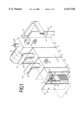
- FIG. 1 in a simplified perspective drawing and partially in section, the apparatus according to the invention, with a loading chamber, a preheating chamber, a heat treatment chamber and a quenching chamber,
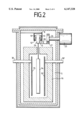
- FIG. 2 a cross section of the preheating chamber according to FIG. 1,
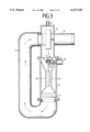
- FIG. 3 a cross section of the quenching chamber according to FIG. 1, and
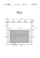
- FIG. 4 a front view of the frame with a stack of saw blades held by said frame.
- the apparatus for the heat treatment of workpieces substantially comprises a loading chamber 3 with a loading gate 2, a preheat chamber 5 arranged serially behind said loading chamber 3 and separated from it by a gate 4, a heat treatment chamber 6 arranged serially behind said preheat chamber 5 and capable of being separated from it by a gate 7, a quenching chamber 8 with gates 9 and 10, arranged serially behind said heat treatment chamber 6, a track 11 extending through all chambers 3, 5, 6, 8 said track having runner surfaces 12, 12' extending horizontally from the side portions of the track to accommodate the roller pairs 13, . . . of the frame-like workpiece holders 14, . . .
- the heating elements 15, 15' arranged in the preheat chamber 5 and enclosed by a well-shaped heat shield 16, a heat exchanger 17 arranged in the quenching chamber 8, and a blower 18 with blower duct 19 and deflector panels 20, 20'.
- the individual workpieces for example saw blades 21, . . . together form a stack which is held by a frame 22 constructed of profile sections, which frame in turn is mounted on a yoke 24 by means of a vertically extending brace 23, 23', said yoke being provided with several roller pairs 13, 13', . . .
- the yoke 24, with the stack of saw blades 21, 21', . . . suspended from it, is movable along a track 11 which extends through all chambers 3, 5, 6, 8.
- Said track is approximately U-shaped where both legs are provided with runner surfaces 12, 12' for the roller pairs 13, 13', . . . and said surfaces being part of a circular conveyor.
- the stack of saw blades 21, 21', . . . is moved by the yoke 24 through the cambers 3, 5, 6, 8 for which movement there are arranged on the side walls of the chambers 8 [sic] parallel shafts with gear wheels 26, . . . driven by motors 25, 25', . . . , with a chain 27 extending over the gear wheels 26, . . . , said chain being capable of coupling, by mean of the catches 28, . . . with said yoke 24 and transporting the frame(s) 22, . . . through the chambers 3, 5, 6, 8.
- the chamber is closed off by the gate 2 so that subsequently the opening of the gate 4 can take place, said gate 4 being connected via a pipe conduit 29 to a vacuum pump, and so that the heating up to the treatment temperature of the saw blades 21, 21', . . . can proceed in the camber 5 under vacuum conditions, after the gate 4 has first been closed.
- the preheat chamber 5, shown schematically in FIG. 2 has heating elements 15, 15' which are connected to an electrical power source via plate lugs 30, 30'.
- the chamber 6 which is designed similar to chamber 5 and is connected to a vacuum pump via a pipe conduit 29'. Said stack can remain in chamber 5 for some time at the treatment temperature and under vacuum conditions. Finally the stack is introduced into the quenching chamber 8, the construction of which is shown in more detail in FIG. 3.
- Said chamber 8 is equipped with a blower 18 which is driven by a motor 31, and has deflector panels 20, 20' which, in the vicinity of the stack, accelerate the quenching gas in the direction indicated by the arrow and then direct said gas to a heat exchanger 17.
- the quenching gas can be fed into the chamber 8 through fittings 32 and can be drawn off after the cooling process by a pump (not shown) or by a vacuum pump connected to the pipe conduits 29, 29'. After the completed quenching process the stack, suspended on track 11, can be removed from the apparatus in the direction of arrow C through the open gate 10.
- a particular advantage of the frame 14 is that the saw blades which are placed one on top of another to form a stack are on the one hand prevented by their own weight from deforming, and on the other can be kept at a temperature which remains approximately stable.
- the stack 21, 21', . . . is weighted down by a weight 33 which has a length and a width approximately equal to that of the blades and which can be placed into the frame parts 22b, 22c formed from U-shaped profile sections.
Abstract
Description
Claims (10)
Priority Applications (1)
| Application Number | Priority Date | Filing Date | Title |
|---|---|---|---|
| US09/584,815 US6207931B1 (en) | 1997-10-24 | 2000-05-31 | Method for the heat treatment of workpieces |
Applications Claiming Priority (2)
| Application Number | Priority Date | Filing Date | Title |
|---|---|---|---|
| DE19747018 | 1997-10-24 | ||
| DE19747018A DE19747018A1 (en) | 1997-10-24 | 1997-10-24 | Heat treatment unit for steel bow saw blades |
Related Child Applications (1)
| Application Number | Title | Priority Date | Filing Date |
|---|---|---|---|
| US09/584,815 Division US6207931B1 (en) | 1997-10-24 | 2000-05-31 | Method for the heat treatment of workpieces |
Publications (1)
| Publication Number | Publication Date |
|---|---|
| US6147328A true US6147328A (en) | 2000-11-14 |
Family
ID=7846505
Family Applications (2)
| Application Number | Title | Priority Date | Filing Date |
|---|---|---|---|
| US09/178,290 Expired - Fee Related US6147328A (en) | 1997-10-24 | 1998-10-23 | Apparatus for the heat treatment of workpieces |
| US09/584,815 Expired - Fee Related US6207931B1 (en) | 1997-10-24 | 2000-05-31 | Method for the heat treatment of workpieces |
Family Applications After (1)
| Application Number | Title | Priority Date | Filing Date |
|---|---|---|---|
| US09/584,815 Expired - Fee Related US6207931B1 (en) | 1997-10-24 | 2000-05-31 | Method for the heat treatment of workpieces |
Country Status (4)
| Country | Link |
|---|---|
| US (2) | US6147328A (en) |
| DE (1) | DE19747018A1 (en) |
| IT (1) | IT1303677B1 (en) |
| SE (1) | SE518581C2 (en) |
Cited By (8)
| Publication number | Priority date | Publication date | Assignee | Title |
|---|---|---|---|---|
| US6506048B1 (en) | 2001-11-01 | 2003-01-14 | Procedyne Corp. | Apparatus and method for transferring heat treated parts |
| CN100449008C (en) * | 2006-08-25 | 2009-01-07 | 权岚 | Saw blade quenching machine |
| CN102952929A (en) * | 2011-08-23 | 2013-03-06 | 克恩-里伯斯(太仓)有限公司 | Continuous heat treatment device and continuous heat treatment method |
| US20130273486A1 (en) * | 2012-04-16 | 2013-10-17 | Benteler Automobiltechnik, GmbH | Layer furnace system and method for operating the layer furnace system |
| CN106500506A (en) * | 2016-12-07 | 2017-03-15 | 宁波好特富工具制造有限公司 | A kind of mower blade production full-automation device |
| WO2019148882A1 (en) * | 2018-02-01 | 2019-08-08 | 福建省长汀金龙稀土有限公司 | Device and method for continuous heat treatment of alloy workpiece or metal workpiece |
| CN114262777A (en) * | 2022-02-25 | 2022-04-01 | 天津紫荆科技有限公司 | Continuous vacuum atmosphere heat treatment equipment |
| US11508519B2 (en) | 2018-02-01 | 2022-11-22 | Fujian Changting Golden Dragon Rare-Earth Co., Ltd | Continous heat treatment device and method for alloy workpiece or metal workpiece |
Families Citing this family (5)
| Publication number | Priority date | Publication date | Assignee | Title |
|---|---|---|---|---|
| US20020184988A1 (en) * | 2001-06-12 | 2002-12-12 | Rohman Kenneth J. | Saw blades and methods for manufacturing saw blades |
| US7003985B2 (en) * | 2001-10-01 | 2006-02-28 | Swain Robert F | Method and apparatus for removing polymeric coatings from optical fiber in a non-oxidizing environment |
| US6436198B1 (en) * | 2001-10-01 | 2002-08-20 | Robert F. Swain | Method and apparatus for removing polymeric coatings from optical fiber |
| DE102006009388B4 (en) | 2006-03-01 | 2009-02-26 | Audi Ag | Apparatus for siliconising carbonaceous materials and method practicable therein |
| ITUB20155822A1 (en) * | 2015-11-23 | 2017-05-23 | Sat Surface Aluminium Tech S P A | SURFACE TREATMENT PLANT FOR PIECES |
Citations (9)
| Publication number | Priority date | Publication date | Assignee | Title |
|---|---|---|---|---|
| US3609295A (en) * | 1970-07-01 | 1971-09-28 | Alco Standard Corp | Heating apparatus with workpiece carriers |
| DE2501360A1 (en) * | 1975-01-15 | 1976-07-22 | Ipsen Ind Int Gmbh | METHOD AND DEVICE FOR GAS CIRCULATION IN A HEAT TREATMENT OVEN |
| DE3233361A1 (en) * | 1982-09-08 | 1984-03-15 | Vsesojuznyj naučno-issledovatel'skij, proektno-konstruktorskij i technologičeskij institut elektrotermiČeskogo oborudovanija, Moskva | Continuous electric furnace for the chemical/thermal treatment of steel components |
| US4610886A (en) * | 1984-06-07 | 1986-09-09 | Knud Simonsen Industries Limited | Multi-conveyor processing system |
| US4886449A (en) * | 1982-12-04 | 1989-12-12 | General Motors Corporation | Vacuum brazing of aluminum alloy workpieces |
| US5039841A (en) * | 1987-09-11 | 1991-08-13 | Senju Metal Industry Co., Ltd. | Reflow furnace |
| DE4110114A1 (en) * | 1990-03-27 | 1991-10-02 | Mazda Motor | DEVICE FOR HEAT TREATING STEEL PARTS |
| US5154338A (en) * | 1990-06-06 | 1992-10-13 | Senju Metal Industry Co., Ltd. | Solder reflow furnace |
| US5163599A (en) * | 1989-10-06 | 1992-11-17 | Hitachi Techno Engineering Co., Ltd. | Reflow soldering apparatus |
Family Cites Families (6)
| Publication number | Priority date | Publication date | Assignee | Title |
|---|---|---|---|---|
| US3673678A (en) * | 1970-05-08 | 1972-07-04 | Alco Standard Corp | Fluxless brazing process |
| US3697725A (en) * | 1971-05-06 | 1972-10-10 | Alco Standard Corp | Heating apparatus with removable heating elements and shields |
| US3767381A (en) * | 1971-07-28 | 1973-10-23 | Alco Standard Corp | Furnace and method of using the same for reclaiming metal |
| DE3233612C2 (en) | 1982-09-10 | 1984-07-26 | Bodenseewerk Gerätetechnik GmbH, 7770 Überlingen | Device for determining the north direction |
| DE3717568A1 (en) * | 1987-05-25 | 1988-12-08 | Lach Spezial Werkzeuge Gmbh | METHOD AND DEVICE FOR MECHANICAL GRINDING OF WORKPIECES BY MEANS OF ELECTRICALLY CONDUCTIVE GRINDING TOOLS |
| DE4422588C2 (en) * | 1994-06-28 | 1999-09-23 | Ald Vacuum Techn Gmbh | Process for quenching workpieces with gases and heat treatment system to carry out the process |
-
1997
- 1997-10-24 DE DE19747018A patent/DE19747018A1/en not_active Withdrawn
-
1998
- 1998-09-09 IT IT1998MI001984A patent/IT1303677B1/en active
- 1998-09-11 SE SE9803093A patent/SE518581C2/en not_active IP Right Cessation
- 1998-10-23 US US09/178,290 patent/US6147328A/en not_active Expired - Fee Related
-
2000
- 2000-05-31 US US09/584,815 patent/US6207931B1/en not_active Expired - Fee Related
Patent Citations (13)
| Publication number | Priority date | Publication date | Assignee | Title |
|---|---|---|---|---|
| US3609295A (en) * | 1970-07-01 | 1971-09-28 | Alco Standard Corp | Heating apparatus with workpiece carriers |
| DE2117398A1 (en) * | 1970-07-01 | 1972-01-05 | Alco Standard Corp | Device for heating workpieces |
| DE2501360A1 (en) * | 1975-01-15 | 1976-07-22 | Ipsen Ind Int Gmbh | METHOD AND DEVICE FOR GAS CIRCULATION IN A HEAT TREATMENT OVEN |
| US4086050A (en) * | 1975-01-15 | 1978-04-25 | Ipsen Industries International | Method and apparatus for gas circulation in a heat treating furnace |
| DE3233361A1 (en) * | 1982-09-08 | 1984-03-15 | Vsesojuznyj naučno-issledovatel'skij, proektno-konstruktorskij i technologičeskij institut elektrotermiČeskogo oborudovanija, Moskva | Continuous electric furnace for the chemical/thermal treatment of steel components |
| US4886449A (en) * | 1982-12-04 | 1989-12-12 | General Motors Corporation | Vacuum brazing of aluminum alloy workpieces |
| US4610886A (en) * | 1984-06-07 | 1986-09-09 | Knud Simonsen Industries Limited | Multi-conveyor processing system |
| US5039841A (en) * | 1987-09-11 | 1991-08-13 | Senju Metal Industry Co., Ltd. | Reflow furnace |
| US5163599A (en) * | 1989-10-06 | 1992-11-17 | Hitachi Techno Engineering Co., Ltd. | Reflow soldering apparatus |
| DE4110114A1 (en) * | 1990-03-27 | 1991-10-02 | Mazda Motor | DEVICE FOR HEAT TREATING STEEL PARTS |
| US5273585A (en) * | 1990-03-27 | 1993-12-28 | Mazda Motor Corporation | Heat-treating apparatus |
| US5871806A (en) * | 1990-03-27 | 1999-02-16 | Mazda Motor Corporation | Heat-treating process |
| US5154338A (en) * | 1990-06-06 | 1992-10-13 | Senju Metal Industry Co., Ltd. | Solder reflow furnace |
Cited By (8)
| Publication number | Priority date | Publication date | Assignee | Title |
|---|---|---|---|---|
| US6506048B1 (en) | 2001-11-01 | 2003-01-14 | Procedyne Corp. | Apparatus and method for transferring heat treated parts |
| CN100449008C (en) * | 2006-08-25 | 2009-01-07 | 权岚 | Saw blade quenching machine |
| CN102952929A (en) * | 2011-08-23 | 2013-03-06 | 克恩-里伯斯(太仓)有限公司 | Continuous heat treatment device and continuous heat treatment method |
| US20130273486A1 (en) * | 2012-04-16 | 2013-10-17 | Benteler Automobiltechnik, GmbH | Layer furnace system and method for operating the layer furnace system |
| CN106500506A (en) * | 2016-12-07 | 2017-03-15 | 宁波好特富工具制造有限公司 | A kind of mower blade production full-automation device |
| WO2019148882A1 (en) * | 2018-02-01 | 2019-08-08 | 福建省长汀金龙稀土有限公司 | Device and method for continuous heat treatment of alloy workpiece or metal workpiece |
| US11508519B2 (en) | 2018-02-01 | 2022-11-22 | Fujian Changting Golden Dragon Rare-Earth Co., Ltd | Continous heat treatment device and method for alloy workpiece or metal workpiece |
| CN114262777A (en) * | 2022-02-25 | 2022-04-01 | 天津紫荆科技有限公司 | Continuous vacuum atmosphere heat treatment equipment |
Also Published As
| Publication number | Publication date |
|---|---|
| IT1303677B1 (en) | 2001-02-23 |
| ITMI981984A1 (en) | 2000-03-09 |
| SE518581C2 (en) | 2002-10-29 |
| DE19747018A1 (en) | 1999-04-29 |
| ITMI981984A0 (en) | 1998-09-09 |
| SE9803093L (en) | 1999-04-25 |
| US6207931B1 (en) | 2001-03-27 |
| SE9803093D0 (en) | 1998-09-11 |
Similar Documents
| Publication | Publication Date | Title |
|---|---|---|
| US6147328A (en) | Apparatus for the heat treatment of workpieces | |
| KR900003516B1 (en) | Continuos type atmosphere heat treating furnace | |
| EP0827489A1 (en) | Process and plant for hardening glass plates | |
| US20180010856A1 (en) | Continuous furnace system having heat recycling device | |
| CN1657281A (en) | Air-exhausting lehr for laminated glass sheets | |
| JPH06511514A (en) | Equipment for heat treating metal workpieces | |
| JP2006063363A (en) | Heat treatment facility | |
| CA1236292A (en) | Furnace | |
| JPH03257119A (en) | Roller hearth type vacuum furnace | |
| KR101884103B1 (en) | Steel plate heating method and steel plate heating device | |
| KR900002524B1 (en) | Apparatus and method for locally heating conveyed glass sheets | |
| US1774161A (en) | Combined oven and carrier for the treatment of bottles | |
| US20030167652A1 (en) | Drying apparatus | |
| KR200318436Y1 (en) | Roller Hearth kiln for forming paste film in PDP | |
| JPS6116912B2 (en) | ||
| US3957479A (en) | Glass treating furnace | |
| JP4044686B2 (en) | drying furnace | |
| US2194612A (en) | Apparatus for case hardening glass | |
| US2576218A (en) | Sheet material conveying and supporting means | |
| US3930831A (en) | Furnace for heat treating glass sheet material | |
| CN217398934U (en) | Heat treatment equipment with preheating function for casting processing | |
| US2440692A (en) | Cooling chamber having baffles for directing air over dried material | |
| JPS6056402B2 (en) | Heat treatment equipment for forged products | |
| JP2007511734A (en) | Furnace system with movable lock chamber | |
| CN106048160A (en) | Push-plate-type salt-bath quenching automatic production line |
Legal Events
| Date | Code | Title | Description |
|---|---|---|---|
| AS | Assignment |
Owner name: ALD VACUUM TECHNOLOGIES AKTIENGESELLSCHAFT, GERMAN Free format text: CHANGE OF NAME;ASSIGNOR:ALD VACUUM TECHNOLOGIES GMBH;REEL/FRAME:010676/0265 Effective date: 20000203 |
|
| AS | Assignment |
Owner name: ALD VACUUM TECHNOLOGIES AG, GERMANY Free format text: ASSIGNMENT OF ASSIGNORS INTEREST;ASSIGNORS:LOSER, KLAUS;ZENKER, WILFRIED;REEL/FRAME:011061/0801;SIGNING DATES FROM 20000808 TO 20000810 |
|
| REMI | Maintenance fee reminder mailed | ||
| LAPS | Lapse for failure to pay maintenance fees | ||
| STCH | Information on status: patent discontinuation |
Free format text: PATENT EXPIRED DUE TO NONPAYMENT OF MAINTENANCE FEES UNDER 37 CFR 1.362 |
|
| FP | Lapsed due to failure to pay maintenance fee |
Effective date: 20041114 |