US6132194A - Low cost compact design integral brake - Google Patents
Low cost compact design integral brake Download PDFInfo
- Publication number
- US6132194A US6132194A US09/325,271 US32527199A US6132194A US 6132194 A US6132194 A US 6132194A US 32527199 A US32527199 A US 32527199A US 6132194 A US6132194 A US 6132194A
- Authority
- US
- United States
- Prior art keywords
- brake
- chamber
- disposed
- lock piston
- engagement
- Prior art date
- Legal status (The legal status is an assumption and is not a legal conclusion. Google has not performed a legal analysis and makes no representation as to the accuracy of the status listed.)
- Expired - Lifetime
Links
Images


Classifications
-
- F—MECHANICAL ENGINEERING; LIGHTING; HEATING; WEAPONS; BLASTING
- F04—POSITIVE - DISPLACEMENT MACHINES FOR LIQUIDS; PUMPS FOR LIQUIDS OR ELASTIC FLUIDS
- F04C—ROTARY-PISTON, OR OSCILLATING-PISTON, POSITIVE-DISPLACEMENT MACHINES FOR LIQUIDS; ROTARY-PISTON, OR OSCILLATING-PISTON, POSITIVE-DISPLACEMENT PUMPS
- F04C2/00—Rotary-piston machines or pumps
- F04C2/08—Rotary-piston machines or pumps of intermeshing-engagement type, i.e. with engagement of co-operating members similar to that of toothed gearing
- F04C2/10—Rotary-piston machines or pumps of intermeshing-engagement type, i.e. with engagement of co-operating members similar to that of toothed gearing of internal-axis type with the outer member having more teeth or tooth-equivalents, e.g. rollers, than the inner member
- F04C2/103—Rotary-piston machines or pumps of intermeshing-engagement type, i.e. with engagement of co-operating members similar to that of toothed gearing of internal-axis type with the outer member having more teeth or tooth-equivalents, e.g. rollers, than the inner member one member having simultaneously a rotational movement about its own axis and an orbital movement
- F04C2/104—Rotary-piston machines or pumps of intermeshing-engagement type, i.e. with engagement of co-operating members similar to that of toothed gearing of internal-axis type with the outer member having more teeth or tooth-equivalents, e.g. rollers, than the inner member one member having simultaneously a rotational movement about its own axis and an orbital movement having an articulated driving shaft
-
- F—MECHANICAL ENGINEERING; LIGHTING; HEATING; WEAPONS; BLASTING
- F04—POSITIVE - DISPLACEMENT MACHINES FOR LIQUIDS; PUMPS FOR LIQUIDS OR ELASTIC FLUIDS
- F04C—ROTARY-PISTON, OR OSCILLATING-PISTON, POSITIVE-DISPLACEMENT MACHINES FOR LIQUIDS; ROTARY-PISTON, OR OSCILLATING-PISTON, POSITIVE-DISPLACEMENT PUMPS
- F04C15/00—Component parts, details or accessories of machines, pumps or pumping installations, not provided for in groups F04C2/00 - F04C14/00
- F04C15/0057—Driving elements, brakes, couplings, transmission specially adapted for machines or pumps
- F04C15/0084—Brakes, braking assemblies
Definitions
- the present invention relates to rotary fluid pressure devices, and more particularly, to such devices of the type including a fluid displacement mechanism which comprises a gerotor gear set.
- the present invention may be included in a gerotor-type device being utilized as a pump, it is especially adapted for use in a low-speed, high-torque gerotor motor, and will be described in connection therewith.
- parking brake or parking lock In many vehicle applications for low-speed, high-torque gerotor motors, it is desirable for the motor to have some sort of parking brake or parking lock, the term “lock” being preferred in some instances because it is intended that the parking lock be engaged only after the vehicle is stopped. In other words, such parking lock devices are not intended to be dynamic brakes, which would be engaged while the vehicle is moving, to bring the vehicle to a stop.
- brake will generally be used hereinafter to mean and include both brakes and locks, the term “brake” being somewhat preferred to distinguish from a device which would operate either fully engaged or fully disengaged.
- the majority of the braking "torque" is provided by a set of brake discs.
- the brake discs are provided with some sort of friction material which, while effective in increasing the braking torque, also adds substantially to the cost of the brake discs.
- friction material which, while effective in increasing the braking torque, also adds substantially to the cost of the brake discs.
- gerotor motor including a parking brake which overcomes the above-described disadvantages of the prior art, and is compact and of low cost.
- a rotary fluid pressure device of the type including a housing defining a fluid inlet and a fluid outlet.
- a rotary fluid displacement mechanism includes an internally-toothed ring member and an externally-toothed star member eccentrically disposed within the ring member for orbital and rotational movement relative thereto, the star member defining a central opening.
- the teeth of the ring member and the star member interengage to define expanding and contracting fluid volume chambers in response to the orbital and rotational movement.
- Valve means cooperates with the housing to provide fluid communication from the fluid inlet to the expanding volume chambers, and from the contracting volume chambers to the fluid outlet.
- a drive shaft includes a driven portion in engagement with the central opening of the star member, a drive portion extending forwardly and adapted to drive an output, and a brake portion extending rearwardly and engaging in orbital and rotational movement.
- An endcap assembly is disposed rearwardly of the fluid displacement mechanism, and defines an internal chamber and a lock piston disposed in the internal chamber, the lock piston being moveable between a first, retracted position, and a second, engaged position.
- the improved rotary fluid pressure device is characterized by the endcap assembly defining a generally cylindrical brake chamber, the brake portion of the drive shaft extending axially into the brake chamber.
- a generally cylindrical brake member is disposed in the brake chamber and is driven eccentrically by the brake portion of the drive shaft.
- the brake member includes a first, generally circular surface disposed for frictional engagement with the lock piston when the lock piston is in the engaged position.
- the brake member also includes a second, generally annular surface disposed for frictional engagement with the fluid displacement mechanism when the lock piston is in the engaged position.
- the improved rotary fluid pressure device is characterized by the generally cylindrical brake member including a cylindrical outer surface in frictional engagement with an internal generally cylindrical surface defined by the brake chamber when the lock piston is in its engaged position, and in response to the orbital and rotational movement of the brake portion of the drive shaft.
- FIG. 1 is an axial cross-section of a gerotor motor including a parking brake made in accordance with the present invention.
- FIG. 2 is a transverse cross-section taken on line 2--2 of FIG. 1, and on approximately the same scale.
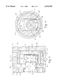
- FIG. 3 is an enlarged, fragmentary, axial cross-section, similar to FIG. 1, illustrating the parking brake of the present invention in greater detail.
- FIG. 4 is an enlarged, fragmentary, transverse cross-section, similar to FIG. 2, and on about the same scale as FIG. 3, illustrating the parking brake of the present invention.
- FIG. 1 is an axial cross-section of a low-speed, high-torque gerotor motor of the type with which the parking brake mechanism of the present invention is especially advantageous.
- the gerotor motor shown in FIG. 1 may be of the general type illustrated and described in U.S. Pat. No. 4,592,704, assigned to the assignee of the present invention and incorporated herein by reference.
- the gerotor motor of FIG. 1 comprises a valve housing section 11, a port plate 13, and a fluid energy-translating displacement mechanism, generally designated 15, which, in the subject embodiment, is a roller gerotor gear set.
- the motor includes a forward endcap 17, held in tight sealing engagement with the valve housing section 11 by means of a plurality of bolts 19, and a rearward endcap assembly 21, held in tight sealing engagement with the valve housing section 11 by means of a plurality of bolts 23.
- the valve housing section 11 includes a fluid inlet port 25, and a fluid outlet port 27, shown only in dashed lines in FIG. 1. It is understood by those skilled in the art that the ports 25 and 27 may be reversed, thus reversing the direction of operation of the motor.
- the gerotor gear set 15 includes an internally-toothed ring member 29, through which the bolts 23 pass (only one of the bolts 23 being shown in FIG. 1), and an externally-toothed star member 31.
- the internal teeth of the ring member 29 comprise a plurality of cylindrical rollers 33, as is now well known in the art.
- the teeth 33 of the ring 29 and the external teeth of the star 31 interengage to define a plurality of expanding volume chambers 35, and a plurality of contracting volume chambers 37, as is also well known in the art.
- the valve housing section 11 defines a spool bore 39, and rotatably disposed therein is a spool valve 41. Formed integrally with the spool valve 41 is an output shaft 43, shown only fragmentarily in FIG. 1.
- an opening 45 defined by the port plate 13
- an axial passage 47 formed in the valve housing section 11.
- Each of the axial passages 47 communicates with the spool bore 39 through an opening 49.
- the housing section 11 also defines fluid passages 25p and 27p, providing fluid communication between the spool bore 39 and the inlet port 25 and outlet port 27, respectively.
- a main drive shaft 51 Disposed within the hollow, cylindrical spool valve 41 is a main drive shaft 51, commonly referred to as a "dog bone" shaft.
- the spool valve 41 defines a set of straight internal splines 53
- the star 31 defines a set of straight internal splines 55.
- the drive shaft 51 includes a set of external crowned splines 57 in engagement with the internal splines 53, and a set of external crowned splines 59 in engagement with the internal splines 55.
- the spool valve 41 defines an annular groove 61 in continuous fluid communication with the inlet port 25, through the passage 25p. Similarly, the spool valve 41 defines an annular groove 63, which is in continuous fluid communication with the outlet port 27, through the passage 27p.
- the spool valve 41 further defines a plurality of axial slots 65 in communication with the annular groove 61, and a plurality of axial slots 67 in communication with the annular groove 63.
- the axial slots 65 and 67 are also frequently referred to as feed slots or timing slots.
- the axial slots 65 provide fluid communication between the annular groove 61 and the openings 49, disposed on one side of the line of eccentricity of the gerotor set 15, while the axial slots 67 provide fluid communication between the annular groove 63 and the openings 49, which are on the other side of the line of eccentricity.
- the resulting commutating valve action between the axial slots 65 and 67 and the openings 49, as the spool valve 41 rotates, is well known in the art and will not be described further herein.
- the rearward endcap assembly 21 defines a relatively larger, internal chamber 71, and a relatively smaller, forward internal chamber 73.
- both of the chambers 71 and 73 are generally cylindrical, although it should be understood that such is not an essential feature of the invention with regard to the chamber 71.
- the chamber 73 must be cylindrical, and the reference numeral "73" will be used hereinafter also for the cylindrical, internal surface of the smaller, forward chamber.
- a generally cylindrical lock piston 75 Disposed within the chamber 71 is a generally cylindrical lock piston 75, which includes an o-ring seal 77 disposed about its outer periphery and in sealing engagement with the internal surface of the chamber 71.
- the lock piston 75 includes a forward, generally circular engagement surface 79.
- the brake member 91 Disposed within the chamber 73 is a generally cylindrical brake member 91.
- the brake member 91 includes a cylindrical outer surface 93 in closely spaced apart, sliding engagement with the cylindrical internal surface 73.
- the brake member 91 defines an internal chamber 95 bounded, in part, by a pair of flat surfaces 97, the function of which will become apparent subsequently.
- a spinner member 99 Disposed within the chamber 95 is a spinner member 99 which includes a pair of flat sides 101, each of which is in closely spaced apart, sliding engagement with one of the flat surfaces 97.
- the spinner member 99 is able to move slightly within the internal chamber 95, in response to the orbital and rotational movement of the main drive shaft 51.
- the spinner member 99 defines a cylindrical internal surface 103, and in closely spaced apart, sliding engagement therewith is an outer cylindrical surface 105 of a rearward end 107 of the main drive shaft 51.
- the rearward end 107 of the drive shaft 51 will also be referred to hereinafter as the "brake portion" of the drive shaft 51, in view of the fact that it is involved in the process of braking the gerotor motor, as will be described subsequently.
- the axis of rotation A of the brake portion 107 is in the position shown in FIG. 4 at the instant in time represented by FIG. 4, but, as is well known to those skilled in the art of orbiting and rotating gerotor devices, the axis of rotation A forms a circle (dashed line) as the star 31 undergoes one complete orbit within the ring member 29.
- the brake member 91 defines a rearward, generally circular surface 109 which is in engagement with the engagement surface 79 of the lock piston 75, whenever the lock piston is biased to the left in FIG. 3 to the engaged position, under the influence of the Belleville washer 85.
- the portion of the internal chamber 71, forward of the lock piston 75 comprises a release chamber 111, and whenever the chamber 111 is subjected to a certain, predetermined pressure, the lock piston 75 is biased to the right in FIGS. 1 and 3, in opposition to the biasing force of the Belleville washer 85.
- the particular arrangement for providing the hydraulic pressure release to the chamber 111 is not an essential feature of the invention.
- the motor may be provided with a separate case drain port which may either be communicated to the system reservoir, or may be restricted to cause a back pressure (higher pressure) within the case drain region, which as is well understood by those skilled in the art, is the open chamber surrounding the main drive shaft 51.
- case pressure is to be used to disengage the brake
- the brake member 91 may be provided with a passage 113, thus permitting communication from the case drain region to the release chamber 111.
- the brake member 91 also includes a forward, generally annular surface 115 which, as may best be seen in FIG. 4 is not perfectly annular, but is referred to as being "generally" annular because of the effect of the flat surfaces 97. Thus, the surface 115 represents a substantial amount of area in engagement with the adjacent surface of the wear plate 89.
- the release chamber 111 When it is desired to engage the brake, the release chamber 111 is drained to tank such that the Belleville washer 85 biases the lock piston 75 forwardly (to the left in FIGS. 1 and 3) into the engaged condition.
- the Belleville washer 85 exerts a certain, predetermined axial force F1 against the lock piston 75, which is then applied by the lock piston 75 to the brake member 91, biasing the annular surface 115 into engagement with the wear plate 89.
- the lock piston 75 does not rotate, such that the circular surface 109 of the brake member 91 is in frictional engagement with the stationary engagement surface 79 of the lock piston 75.
- the annular surface 115 of the brake member 91 is also in engagement with a stationary surface, i.e., the adjacent surface of the wear plate 89.
- each of those separate sources of braking torque identified hereinafter as T1, T2, T3 and T4 will be described separately, it being understood that the total braking torque T is the summation of the four individual braking torques.
- the braking torque T1 is the result of the engagement of the engagement surface 79 and the circular surface 109 and is determined as follows:
- the braking torque T2 is that which occurs at the interface of the generally annular surface 115 and the adjacent surface of the wear plate 89 and is calculated as follows:
- R2 equals the effective diameter of the area of engagement of the surface 115 divided by 4 and the adjacent surface of the wear plate 89; and ⁇ 2 equals the coefficient of static friction at the interface of the surface 115 and the wear plate 89.
- the braking torque T3 relates to the engagement of the internal chamber surface 73 and the cylindrical outer surface 93, and is determined as follows: ##EQU1## wherein e equals the eccentricity of the axis of rotation A of the brake portion 107; ⁇ 3 equals the coefficient of static friction at the interface of the surfaces 73 and 93; and D3 equals the diameter of the surface 93.
- the braking torque T4 relates to the engagement of the internal surface 103 and the outer cylindrical surface 105 and is determined as follows: ##EQU2## wherein ⁇ 4 equals the coefficient of static friction at the interface of the surfaces 103 and 105; 7 equals the number of orbits, plus one, of the brake portion 107, per revolution; and D4 equals the diameter of the surface 105.
- the braking torques T1 and T2 together equal approximately ninety percent of the total braking torque, whereas the braking torque T3 equals about eight percent of the total, and the braking torque T4 equals about two percent of the total. It has been observed in connection with the development of the present invention that if the braking torques T3 plus T4 are too high, or become too high, as a percent of the total braking torque, there will be a tendency for the mechanism to actuate on its own, or stated another way, to become "self-locking", which is understood by those skilled in the vehicle brake art to be undesirable.
- the circular surface 109 of the brake member 91 is in direct, frictional engagement with the engagement surface 79 of the lock piston 75. It will be understood that references hereinafter, and in the appended claims, to such frictional engagement include both the direct engagement illustrated herein, as well as indirect engagement which results if some sort of member is interposed between the surfaces 79 and 109. The same would be true if some sort of member were interposed between the surface 115 and the wear plate 89.
- the brake arrangement of the invention will provide at least a portion of the capacity, but at less cost, and in a more compact package. This is especially true because of the fact that the invention takes advantage of the orbiting brake portion 107, whereby the brake member 91 is rotating at orbit speed, thus effectively reducing the area of engagement and normal force (F1) required to achieve a particular braking torque.
Landscapes
- Engineering & Computer Science (AREA)
- Mechanical Engineering (AREA)
- General Engineering & Computer Science (AREA)
- Hydraulic Motors (AREA)
- Braking Arrangements (AREA)
Priority Applications (5)
| Application Number | Priority Date | Filing Date | Title |
|---|---|---|---|
| US09/325,271 US6132194A (en) | 1999-06-03 | 1999-06-03 | Low cost compact design integral brake |
| DE60001870T DE60001870T2 (de) | 1999-06-03 | 2000-05-16 | Gerotormotor und Bremsbaugruppe |
| EP00110434A EP1058007B1 (de) | 1999-06-03 | 2000-05-16 | Innenzahnradmotor und Feststellbremse |
| BR0001963-1A BR0001963A (pt) | 1999-06-03 | 2000-05-26 | Freio integral de projeto compacto e baixo custo |
| JP2000167834A JP4538770B2 (ja) | 1999-06-03 | 2000-06-05 | 回転流体圧装置 |
Applications Claiming Priority (1)
| Application Number | Priority Date | Filing Date | Title |
|---|---|---|---|
| US09/325,271 US6132194A (en) | 1999-06-03 | 1999-06-03 | Low cost compact design integral brake |
Publications (1)
| Publication Number | Publication Date |
|---|---|
| US6132194A true US6132194A (en) | 2000-10-17 |
Family
ID=23267175
Family Applications (1)
| Application Number | Title | Priority Date | Filing Date |
|---|---|---|---|
| US09/325,271 Expired - Lifetime US6132194A (en) | 1999-06-03 | 1999-06-03 | Low cost compact design integral brake |
Country Status (5)
| Country | Link |
|---|---|
| US (1) | US6132194A (de) |
| EP (1) | EP1058007B1 (de) |
| JP (1) | JP4538770B2 (de) |
| BR (1) | BR0001963A (de) |
| DE (1) | DE60001870T2 (de) |
Cited By (15)
| Publication number | Priority date | Publication date | Assignee | Title |
|---|---|---|---|---|
| US6321882B1 (en) * | 1999-08-25 | 2001-11-27 | Eaton Corporation | External manual brake release |
| US20030101720A1 (en) * | 2001-11-08 | 2003-06-05 | Walls James L. | Hydraulic gerotor motor with integral shuttle valve |
| US6743002B1 (en) | 2003-02-03 | 2004-06-01 | Eaton Corporation | Rotary fluid pressure device and improved integral brake assembly |
| US20060159581A1 (en) * | 2005-01-18 | 2006-07-20 | Thomas R. Fugle | Rotary fluid pressure device and improved brake assembly for use therewith |
| US20080240959A1 (en) * | 2007-03-30 | 2008-10-02 | Eiji Fukuchi | Brake releasing mechanism and brake system |
| US20100166590A1 (en) * | 2006-01-20 | 2010-07-01 | Eaton Corporation | Rotary fluid pressure device and improved parking lock assembly therefor |
| US20100178188A1 (en) * | 2006-05-08 | 2010-07-15 | White Drive Products, Inc. | Gerotor motor and brake assembly |
| CN101839209A (zh) * | 2010-05-11 | 2010-09-22 | 镇江大力液压马达有限责任公司 | 内置式制动摆线液压马达 |
| US20110250086A1 (en) * | 2010-04-13 | 2011-10-13 | Eaton Corporation | Frame rotated hydraulic motor with improved parking brake |
| US8796875B2 (en) | 2012-11-20 | 2014-08-05 | Turbogen, Llc | Housing apparatus for use with an electrical system and method of using same |
| US8907512B2 (en) | 2012-11-20 | 2014-12-09 | Turbogen, Llc | Load apparatus and method of using same |
| US9175563B2 (en) | 2012-07-18 | 2015-11-03 | Eaton Corporation | Combined motor and brake with rotating brake-release piston |
| US9551222B2 (en) | 2012-07-18 | 2017-01-24 | Eaton Corporation | Freewheel hydraulic motor |
| US10781816B2 (en) | 2017-04-13 | 2020-09-22 | Eaton Intelligent Power Limited | Hydraulic motor brake |
| WO2022243968A1 (en) | 2021-05-21 | 2022-11-24 | Danfoss Power Solutions Ii Technology A/S | Hydraulic drive device comprising a gerotor type motor with a friction brake |
Families Citing this family (1)
| Publication number | Priority date | Publication date | Assignee | Title |
|---|---|---|---|---|
| CN103758691A (zh) * | 2014-01-09 | 2014-04-30 | 山东瑞诺液压机械有限公司 | 集成内置强制湿式自锁式摆线液压马达结构 |
Citations (11)
| Publication number | Priority date | Publication date | Assignee | Title |
|---|---|---|---|---|
| US3087436A (en) * | 1960-12-02 | 1963-04-30 | Ross Gear And Tool Company Inc | Hydraulic pump |
| US3616882A (en) * | 1970-02-05 | 1971-11-02 | Trw Inc | Hydraulic motor-pump assembly with built-in brake |
| US3960470A (en) * | 1975-03-17 | 1976-06-01 | Trw Inc. | Hydraulic motor brake |
| DE3125087A1 (de) * | 1981-06-26 | 1983-01-13 | Danfoss A/S, 6430 Nordborg | "bremse fuer einen hydraulischen motor" |
| WO1984001800A1 (en) * | 1982-11-01 | 1984-05-10 | Nichols Co W H | Hydraulic torque device |
| US4493404A (en) * | 1982-11-22 | 1985-01-15 | Eaton Corporation | Hydraulic gerotor motor and parking brake for use therein |
| US4597476A (en) * | 1983-04-04 | 1986-07-01 | Eaton Corporation | Hydraulic gerotor motor and parking brake for use therein |
| US4613292A (en) * | 1985-02-01 | 1986-09-23 | Eaton Corporation | Hydraulic motor having free-wheeling and locking modes of operation |
| US4981423A (en) * | 1989-10-03 | 1991-01-01 | Trw Inc. | Hydraulic motor with wobble-stick and brake assembly |
| US5144324A (en) * | 1989-08-02 | 1992-09-01 | At&T Bell Laboratories | Antenna arrangement for a portable transceiver |
| US6602835B2 (en) * | 2001-06-06 | 2003-08-05 | Pennzoil-Quaker State Company | Composition and method for cleaning, protecting and restoring vehicular surfaces |
Family Cites Families (4)
| Publication number | Priority date | Publication date | Assignee | Title |
|---|---|---|---|---|
| JPS6053193B2 (ja) * | 1981-11-17 | 1985-11-25 | 住友イ−トン機器株式会社 | 油圧モ−タにおけるブレ−キ装置 |
| JP2839063B2 (ja) * | 1993-06-17 | 1998-12-16 | 住友イートン機器株式会社 | 油圧モータのブレーキ装置 |
| US6062835A (en) * | 1997-01-14 | 2000-05-16 | Eaton Corporation | Gerotor motor and parking lock assembly therefor |
| EP0870922A1 (de) * | 1997-04-10 | 1998-10-14 | Eaton Corporation | Bremse für einen Innenzahnradmotor |
-
1999
- 1999-06-03 US US09/325,271 patent/US6132194A/en not_active Expired - Lifetime
-
2000
- 2000-05-16 EP EP00110434A patent/EP1058007B1/de not_active Expired - Lifetime
- 2000-05-16 DE DE60001870T patent/DE60001870T2/de not_active Expired - Lifetime
- 2000-05-26 BR BR0001963-1A patent/BR0001963A/pt not_active IP Right Cessation
- 2000-06-05 JP JP2000167834A patent/JP4538770B2/ja not_active Expired - Fee Related
Patent Citations (11)
| Publication number | Priority date | Publication date | Assignee | Title |
|---|---|---|---|---|
| US3087436A (en) * | 1960-12-02 | 1963-04-30 | Ross Gear And Tool Company Inc | Hydraulic pump |
| US3616882A (en) * | 1970-02-05 | 1971-11-02 | Trw Inc | Hydraulic motor-pump assembly with built-in brake |
| US3960470A (en) * | 1975-03-17 | 1976-06-01 | Trw Inc. | Hydraulic motor brake |
| DE3125087A1 (de) * | 1981-06-26 | 1983-01-13 | Danfoss A/S, 6430 Nordborg | "bremse fuer einen hydraulischen motor" |
| WO1984001800A1 (en) * | 1982-11-01 | 1984-05-10 | Nichols Co W H | Hydraulic torque device |
| US4493404A (en) * | 1982-11-22 | 1985-01-15 | Eaton Corporation | Hydraulic gerotor motor and parking brake for use therein |
| US4597476A (en) * | 1983-04-04 | 1986-07-01 | Eaton Corporation | Hydraulic gerotor motor and parking brake for use therein |
| US4613292A (en) * | 1985-02-01 | 1986-09-23 | Eaton Corporation | Hydraulic motor having free-wheeling and locking modes of operation |
| US5144324A (en) * | 1989-08-02 | 1992-09-01 | At&T Bell Laboratories | Antenna arrangement for a portable transceiver |
| US4981423A (en) * | 1989-10-03 | 1991-01-01 | Trw Inc. | Hydraulic motor with wobble-stick and brake assembly |
| US6602835B2 (en) * | 2001-06-06 | 2003-08-05 | Pennzoil-Quaker State Company | Composition and method for cleaning, protecting and restoring vehicular surfaces |
Cited By (22)
| Publication number | Priority date | Publication date | Assignee | Title |
|---|---|---|---|---|
| US6321882B1 (en) * | 1999-08-25 | 2001-11-27 | Eaton Corporation | External manual brake release |
| US20030101720A1 (en) * | 2001-11-08 | 2003-06-05 | Walls James L. | Hydraulic gerotor motor with integral shuttle valve |
| US6826909B2 (en) | 2001-11-08 | 2004-12-07 | Parker-Hannifin Corp. | Hydraulic gerotor motor with integral shuttle valve |
| US6743002B1 (en) | 2003-02-03 | 2004-06-01 | Eaton Corporation | Rotary fluid pressure device and improved integral brake assembly |
| US20060159581A1 (en) * | 2005-01-18 | 2006-07-20 | Thomas R. Fugle | Rotary fluid pressure device and improved brake assembly for use therewith |
| US7287969B2 (en) | 2005-01-18 | 2007-10-30 | Eaton Corporation | Rotary fluid pressure device and improved brake assembly for use therewith |
| US20100166590A1 (en) * | 2006-01-20 | 2010-07-01 | Eaton Corporation | Rotary fluid pressure device and improved parking lock assembly therefor |
| US8157552B2 (en) | 2006-01-20 | 2012-04-17 | Eaton Corporation | Rotary fluid pressure device and improved parking lock assembly therefor |
| US20100178188A1 (en) * | 2006-05-08 | 2010-07-15 | White Drive Products, Inc. | Gerotor motor and brake assembly |
| US8182250B2 (en) | 2006-05-08 | 2012-05-22 | White Drive Products, Inc. | Gerotor motor and brake assembly |
| WO2008120047A1 (en) * | 2007-03-30 | 2008-10-09 | Eaton Corporation | Brake releasing mechanism and braking system |
| US20080240959A1 (en) * | 2007-03-30 | 2008-10-02 | Eiji Fukuchi | Brake releasing mechanism and brake system |
| US7845919B2 (en) | 2007-03-30 | 2010-12-07 | Eaton Corporation | Brake releasing mechanism and brake system |
| US8500423B2 (en) * | 2010-04-13 | 2013-08-06 | Eaton Corporation | Frame rotated hydraulic motor with improved parking brake |
| US20110250086A1 (en) * | 2010-04-13 | 2011-10-13 | Eaton Corporation | Frame rotated hydraulic motor with improved parking brake |
| CN101839209A (zh) * | 2010-05-11 | 2010-09-22 | 镇江大力液压马达有限责任公司 | 内置式制动摆线液压马达 |
| US9175563B2 (en) | 2012-07-18 | 2015-11-03 | Eaton Corporation | Combined motor and brake with rotating brake-release piston |
| US9551222B2 (en) | 2012-07-18 | 2017-01-24 | Eaton Corporation | Freewheel hydraulic motor |
| US8796875B2 (en) | 2012-11-20 | 2014-08-05 | Turbogen, Llc | Housing apparatus for use with an electrical system and method of using same |
| US8907512B2 (en) | 2012-11-20 | 2014-12-09 | Turbogen, Llc | Load apparatus and method of using same |
| US10781816B2 (en) | 2017-04-13 | 2020-09-22 | Eaton Intelligent Power Limited | Hydraulic motor brake |
| WO2022243968A1 (en) | 2021-05-21 | 2022-11-24 | Danfoss Power Solutions Ii Technology A/S | Hydraulic drive device comprising a gerotor type motor with a friction brake |
Also Published As
| Publication number | Publication date |
|---|---|
| DE60001870D1 (de) | 2003-05-08 |
| EP1058007B1 (de) | 2003-04-02 |
| BR0001963A (pt) | 2001-01-02 |
| JP2001003847A (ja) | 2001-01-09 |
| JP4538770B2 (ja) | 2010-09-08 |
| EP1058007A2 (de) | 2000-12-06 |
| EP1058007A3 (de) | 2001-12-12 |
| DE60001870T2 (de) | 2003-12-11 |
Similar Documents
| Publication | Publication Date | Title |
|---|---|---|
| US6132194A (en) | Low cost compact design integral brake | |
| EP1443212B1 (de) | Gerotor mit einer Bremseinrichtung | |
| US4981423A (en) | Hydraulic motor with wobble-stick and brake assembly | |
| US6321882B1 (en) | External manual brake release | |
| EP0870922A1 (de) | Bremse für einen Innenzahnradmotor | |
| EP1974145B1 (de) | Rotationsfluiddruckvorrichtung und verbesserte parksperranordnung dafür | |
| US4613292A (en) | Hydraulic motor having free-wheeling and locking modes of operation | |
| IE42302B1 (en) | Improvements in or relating to the braking of hydraulic devices | |
| US6062835A (en) | Gerotor motor and parking lock assembly therefor | |
| JP4374558B2 (ja) | 回転流体圧装置 | |
| US5228846A (en) | Spline reduction extension for auxilliary drive component | |
| US4597476A (en) | Hydraulic gerotor motor and parking brake for use therein | |
| EP1070847A2 (de) | Hydraulischer Gerotor-Motor und Feststellbremse | |
| US4493404A (en) | Hydraulic gerotor motor and parking brake for use therein | |
| US6030194A (en) | Gerotor motor and improved valve drive and brake assembly therefor | |
| JP3124014B2 (ja) | ロック機能を有する流体圧モータアセンブリ | |
| EP0124299B1 (de) | Hydraulischer Gerotor-Motor und Feststellbremse zum Gebrauch darin | |
| JP4235850B2 (ja) | 回転流体圧装置 | |
| EP0881391B1 (de) | Innenzahnradmotor mit schwimmender Abdichtung | |
| JP2839063B2 (ja) | 油圧モータのブレーキ装置 | |
| EP0544209A1 (de) | System zur Vergrösserung der tragenden Länge einer Zahnkupplung für den Antrieb eines Hilfsgeräts mit Hilfe eines Reduzierstücks |
Legal Events
| Date | Code | Title | Description |
|---|---|---|---|
| AS | Assignment |
Owner name: EATON CORPORATION, OHIO Free format text: ASSIGNMENT OF ASSIGNORS INTEREST;ASSIGNORS:WENKER, WAYNE B.;BARTO, MICHAEL W.;YAKIMOW, SCOTT E.;REEL/FRAME:010023/0582 Effective date: 19990601 |
|
| STCF | Information on status: patent grant |
Free format text: PATENTED CASE |
|
| FEPP | Fee payment procedure |
Free format text: PAYOR NUMBER ASSIGNED (ORIGINAL EVENT CODE: ASPN); ENTITY STATUS OF PATENT OWNER: LARGE ENTITY |
|
| FPAY | Fee payment |
Year of fee payment: 4 |
|
| FPAY | Fee payment |
Year of fee payment: 8 |
|
| FPAY | Fee payment |
Year of fee payment: 12 |
|
| AS | Assignment |
Owner name: EATON INTELLIGENT POWER LIMITED, IRELAND Free format text: ASSIGNMENT OF ASSIGNORS INTEREST;ASSIGNOR:EATON CORPORATION;REEL/FRAME:048855/0626 Effective date: 20171231 |