EP0881391B1 - Innenzahnradmotor mit schwimmender Abdichtung - Google Patents
Innenzahnradmotor mit schwimmender Abdichtung Download PDFInfo
- Publication number
- EP0881391B1 EP0881391B1 EP98109217A EP98109217A EP0881391B1 EP 0881391 B1 EP0881391 B1 EP 0881391B1 EP 98109217 A EP98109217 A EP 98109217A EP 98109217 A EP98109217 A EP 98109217A EP 0881391 B1 EP0881391 B1 EP 0881391B1
- Authority
- EP
- European Patent Office
- Prior art keywords
- ring
- seal
- seal groove
- star
- fluid pressure
- Prior art date
- Legal status (The legal status is an assumption and is not a legal conclusion. Google has not performed a legal analysis and makes no representation as to the accuracy of the status listed.)
- Expired - Lifetime
Links
- 239000012530 fluid Substances 0.000 claims description 45
- 238000007789 sealing Methods 0.000 claims description 12
- 238000006073 displacement reaction Methods 0.000 claims description 6
- 230000007246 mechanism Effects 0.000 claims description 6
- 229910000831 Steel Inorganic materials 0.000 claims description 2
- 230000004044 response Effects 0.000 claims description 2
- 239000010959 steel Substances 0.000 claims description 2
- 239000000463 material Substances 0.000 description 6
- 230000004048 modification Effects 0.000 description 3
- 238000012986 modification Methods 0.000 description 3
- 230000004075 alteration Effects 0.000 description 2
- 230000004323 axial length Effects 0.000 description 1
- 230000008901 benefit Effects 0.000 description 1
- 230000008859 change Effects 0.000 description 1
- 230000000694 effects Effects 0.000 description 1
- 230000002706 hydrostatic effect Effects 0.000 description 1
- 230000007935 neutral effect Effects 0.000 description 1
- 230000001737 promoting effect Effects 0.000 description 1
Images

Classifications
-
- F—MECHANICAL ENGINEERING; LIGHTING; HEATING; WEAPONS; BLASTING
- F04—POSITIVE - DISPLACEMENT MACHINES FOR LIQUIDS; PUMPS FOR LIQUIDS OR ELASTIC FLUIDS
- F04C—ROTARY-PISTON, OR OSCILLATING-PISTON, POSITIVE-DISPLACEMENT MACHINES FOR LIQUIDS; ROTARY-PISTON, OR OSCILLATING-PISTON, POSITIVE-DISPLACEMENT PUMPS
- F04C15/00—Component parts, details or accessories of machines, pumps or pumping installations, not provided for in groups F04C2/00 - F04C14/00
- F04C15/0003—Sealing arrangements in rotary-piston machines or pumps
- F04C15/0023—Axial sealings for working fluid
- F04C15/0026—Elements specially adapted for sealing of the lateral faces of intermeshing-engagement type machines or pumps, e.g. gear machines or pumps
-
- F—MECHANICAL ENGINEERING; LIGHTING; HEATING; WEAPONS; BLASTING
- F04—POSITIVE - DISPLACEMENT MACHINES FOR LIQUIDS; PUMPS FOR LIQUIDS OR ELASTIC FLUIDS
- F04C—ROTARY-PISTON, OR OSCILLATING-PISTON, POSITIVE-DISPLACEMENT MACHINES FOR LIQUIDS; ROTARY-PISTON, OR OSCILLATING-PISTON, POSITIVE-DISPLACEMENT PUMPS
- F04C2/00—Rotary-piston machines or pumps
- F04C2/08—Rotary-piston machines or pumps of intermeshing-engagement type, i.e. with engagement of co-operating members similar to that of toothed gearing
- F04C2/10—Rotary-piston machines or pumps of intermeshing-engagement type, i.e. with engagement of co-operating members similar to that of toothed gearing of internal-axis type with the outer member having more teeth or tooth-equivalents, e.g. rollers, than the inner member
- F04C2/103—Rotary-piston machines or pumps of intermeshing-engagement type, i.e. with engagement of co-operating members similar to that of toothed gearing of internal-axis type with the outer member having more teeth or tooth-equivalents, e.g. rollers, than the inner member one member having simultaneously a rotational movement about its own axis and an orbital movement
- F04C2/104—Rotary-piston machines or pumps of intermeshing-engagement type, i.e. with engagement of co-operating members similar to that of toothed gearing of internal-axis type with the outer member having more teeth or tooth-equivalents, e.g. rollers, than the inner member one member having simultaneously a rotational movement about its own axis and an orbital movement having an articulated driving shaft
Definitions
- the present invention relates to rotary fluid pressure devices of the type including a gerotor displacement mechanism, and more particularly, to those of the "sealed star" type.
- the present invention may be used advantageously in a gerotor motor or a gerotor pump, it is especially suited for use in a fluid controller such as the steering control unit (SCU) of a full fluid-linked hydrostatic power steering system, and the invention will be described in connection therewith.
- a fluid controller such as the steering control unit (SCU) of a full fluid-linked hydrostatic power steering system
- U.S. Patent No. 4,145,167 illustrates one approach utilized by those skilled in the SCU art, the approach being referred to as a "sealed star" in which a sealing arrangement is disposed on the rearward surface of the gerotor star, in sealing engagement with the adjacent surface of the endcap.
- a sealing arrangement is disposed on the rearward surface of the gerotor star, in sealing engagement with the adjacent surface of the endcap.
- the intention is to prevent leakage of fluid through the gerotor side clearance to the case drain region of the SCU, which is connected to the system reservoir.
- the sealing is accomplished by means of an axial squeeze of the seal assembly, i.e., by compressing the seal assembly axially between the bottom surface of the seal groove and the adjacent surface of the endcap.
- a rotary fluid pressure device of the type comprising housing means defining a fluid inlet port and a fluid outlet port.
- a gerotor displacement mechanism is associated with the housing means, and includes an internally-toothed ring member, and an externally-toothed star member eccentrically disposed within the ring member for orbital and rotational movement relative thereto. The teeth of the ring member and the star member interengage to define a plurality of expanding and contracting fluid volume chamber in response to the orbital and rotational movements.
- a valve means is operably associated with the housing means and with the star member to provide fluid communication from the inlet port to the expanding volume chambers and from the contracting volume chambers to the outlet port.
- the ring member and the star member each include a forward surface disposed toward the valve means, and a rearward surface, the housing means including an endcap disposed in sealing engagement with the rearward surfaces of the ring member and the star member.
- the rearward surface of the star member defines a generally annular seal groove and seal means disposed in the seal groove.
- the improved rotary fluid pressure device is characterized by the seal groove defining a radially inner surface and a radially outer surface.
- the seal means comprises an annular seal ring disposed in the seal groove and in engagement with the endcap, and an annular elastomeric back-up ring disposed in the seal groove, forward of the seal ring.
- the back-up ring is configured such that its inside diameter is smaller than the radially inner surface of the seal groove, and the axial dimension of the seal ring and the back-up ring together is no greater than the axial dimension of the seal groove. In other words, there is no axial squeeze on the seal assembly, but a radial squeeze on the back-up ring, while the seal ring floats.
- FIG. 1 is a partly schematic, partly axial cross-section view of a fluid controller, or steering control unit (SCU) of the type with which the sealed star arrangement of the present invention may be utilized.
- SCU steering control unit
- the SCU may be of the general type illustrated and described in U.S. Patent No. Re. 25,126, and more specifically, of the type illustrated and described in U.S. Patent No. 4,958, 493, both of which are assigned to the assignee of the present invention.
- the SCU will be described only very briefly herein, as the present invention does not involve or require any substantial modification of the rest of the SCU, or change its general operation.
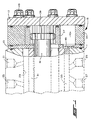
- the SCU comprises several sections, including a valve housing section 11, a wear plate 13, a gerotor displacement mechanism generally designated 15, and an endcap 17. These sections are held together in tight sealing engagement by means of a plurality of bolts 19, which are in threaded engagement with the valve housing 11.
- the valve housing 11 defines a fluid inlet port 21, a fluid return port 23, and a pair of control (cylinder) fluid ports 25 and 27.
- the valve housing 11 defines a valve bore 29, and rotatably disposed therein is the controller valving which comprises a primary, rotatable valve member (spool) 31, and a cooperating, relatively rotatable follow-up valve member (sleeve) 33.
- controller valving which comprises a primary, rotatable valve member (spool) 31, and a cooperating, relatively rotatable follow-up valve member (sleeve) 33.
- the gerotor displacement mechanism 15 may be of the type well known in the art, and includes an internally toothed ring member 35, and an externally toothed star member 37.
- the star member 37 is eccentrically disposed within the ring member 35, for orbital and rotational movement therein.
- the star 37 defines a set of internal splines 39, and in splined engagement therewith is a main drive shaft 41, the forward end of which (not shown in FIG. 1) is in driving engagement with the follow-up valve member 33, in a manner, and for a purpose well known to those skilled in the art.
- the teeth of the ring 35 and the star 37 interengage to define a plurality of fluid volume chambers 43 (only one of which is shown in FIG.
- each of the volume chambers 43 being in communication with the SCU valving through an adjacent opening 45 in the wear plate 13.
- the axial length of the ring member 35 is slightly greater than that of the star member 37, such that the ring 35 is truly in a tight sealing engagement between the wear plate 13 and the end cap 17, whereas the star 37 is free to orbit and rotate, within the ring 35, with some end clearance between the end faces of the star 37 and the adjacent surfaces of the wear plate 13 and the end cap 17.
- the end clearances on the ends of the star 37 are sufficiently small that both the ring and the star may be referred to as being "in sealing engagement" with both the wear plate 13 and the end cap 17.
- the end cap 17 includes a forward surface 47 disposed immediately adjacent a rearward surface 49 of the star member 37.
- the star 37 defines an annular groove 51 which is typically disposed concentrically about the axis of the star 37. It is one benefit of the present invention that the axial depth of the groove 51 is not critical, as was the case for the prior art "axial squeeze" seal arrangement.
- a seal assembly Disposed within the annular groove 51 is a seal assembly, generally designated 53, comprising a steel seal ring 55, and an elastomeric back up ring 57 disposed "under” or forwardly of the seal ring 55. It will be understood by those skilled in the art that the particular materials used for the seal ring 55 and the backup ring 57 are not essential features of the present invention, and the rings 55 and 57 may comprise any of a number of materials conventionally used for such purposes.
- the annular seal groove 51 includes a radially outer surface 58, and a radially inner surface 59.
- the seal assembly 53 is illustrated in its "relaxed" condition, prior to assembly into the seal groove 51.
- the primary purpose of FIG. 3 is to illustrate various dimensional relationships which are an important aspect of the present invention.
- the radially outer surface 58 defines a diameter D1 while the seal ring 55 and backup ring 57 define an outer diameter D2, wherein D2 is somewhat less than D1.
- the outer diameters of the rings 55 and 57 have been shown as approximately equal, although such is not essential to the invention.
- the radially inner surface 59 of the groove 51 defines a diameter D3.
- the backup ring 57 includes an inside diameter 61 which defines a diameter D4, while the seal ring 55 includes an inside diameter 63 which defines a diameter D5.
- the diameter D4 is less than the diameter D3, such that there is a "radial squeeze” on the elastomeric backup ring 57 after “assembly” to the FIG. 2 position, while the diameter D5 is greater than the diameter D3, such that the seal ring 55 is free to "float" within the seal groove 51, after assembly.
- the present invention is not limited to any particular materials for the seal ring 55 and backup ring 57, but instead, any suitable materials may be used which will function satisfactorily.
- the seal ring 55 could comprise a suitable plastic material.
- the backup ring 57 could comprise an O-ring, as long as its "inside diameter” would have a radial squeeze relative to the inner surface 51. It is believed that various other materials and shapes will occur to those skilled in the art in dealing with different applications.
Landscapes
- Engineering & Computer Science (AREA)
- Mechanical Engineering (AREA)
- General Engineering & Computer Science (AREA)
- Rotary Pumps (AREA)
- Details And Applications Of Rotary Liquid Pumps (AREA)
- Hydraulic Motors (AREA)
- Sealing Devices (AREA)
Claims (8)
- Rotationsfluiddruckvorrichtung mit einer Gehäuseanordnung (11), die einen Fluideinlassanschluss (21) und einen Fluidauslassanschluss (23) bestimmt, einem der Gehäuseanordnung (11) zugeordneten Gerotorverdrängungsmechanismus (15), der ein Innenzähne aufweisendes Ringbauteil (35) und ein Außenzähne aufweisendes Sternbauteil (37) aufweist, das für eine Umlauf- und Drehbewegung mit Bezug auf das Ringbauteil (35) innerhalb des Ringbauteils angeordnet ist, wobei die Zähne des Ringbauteils (35) und des Sternbauteils (37) ineinander greifen, um eine Mehrzahl von sich ausdehnenden und sich zusammenziehenden Fluidvolumenkammern (43) in Ansprechen auf die Umlauf- und Drehbewegungen zu bestimmen; einer mit der Gehäuseanordnung (11) und dem Sternbauteil (37) in Wirkverbindung stehenden Ventilanordnung (31, 33) zum Herstellen einer Fluidverbindung von dem Einlassanschluss (21) zu den sich ausdehnenden Volumenkammern (43) und von den sich zusammenziehenden Volumenkammern (43) zu dem Auslassanschluss (23), wobei das Ringbauteil (35) und das Stembauteil (37) jeweils eine in Richtung auf die Ventilanordnung (31, 33) gerichtete vordere Fläche sowie eine hintere Fläche (49) aufweisen, wobei die Gehäuseanordnung (11) eine Endkappe (17) umfasst, die in dichtendem Eingriff mit den hinteren Flächen (49) des Ringbauteils und des Sternbauteils steht, wobei die hintere Fläche (49) des Sternbauteils (37) eine im wesentlichen ringförmige Dichtungsnut bildet, in welcher eine Dichtungsanordnung angeordnet ist; dadurch gekennzeichnet, dass:(a) die Dichtungsnut (51) eine radial innenliegende Fläche (59) und eine radial außenliegende Fläche (58) bestimmt;(b) die Dichtungsanordnung einen ringförmigen Dichtungsring (55), der in der Dichtungsnut (51) angeordnet ist und in Eingriff mit der Endkappe (17) steht, sowie einen ringförmigen elastomeren Stützring (57) aufweist, der in der Dichtungsnut (51) vor dem Dichtungsring (55) angeordnet ist; und(c) der Stützring (57) so konfiguriert ist, dass dessen Innendurchmesser (61) kleiner als die radiale Innenfläche (59) der Dichtungsnut (51) ist, und die axiale Abmessung des Dichtungsrings (55) und des Stützrings (57) zusammen nicht größer als die axiale Abmessung der Dichtungsnut (51) ist.
- Rotationsfluiddruckvorrichtung nach Anspruch 1, dadurch gekennzeichnet, dass die Vorrichtung ein Fluidsteuergerät aufweist, wobei die Gehäuseanordnung (11) einen ersten (25) und einen zweiten (27) Steuerfluidanschluss aufweist, die für eine Verbindung mit einer fluiddruckbetätigten Vorrichtung ausgelegt sind, und wobei die Ventilanordnung ein drehbares Hauptventilorgan (31) und ein relativ drehbares Nachlaufventilorgan (33) aufweist.
- Rotationsfluiddruckvorrichtung nach Anspruch 2, gekennzeichnet durch eine Anordnung (41), die betätigbar ist, um die Drehbewegung des Sternbauteils (37) in eine Nachlaufbewegung des Nachlaufventilorgans (33) umzusetzen.
- Rotationsfluiddruckvorrichtung nach Anspruch 1, dadurch gekennzeichnet, dass der Stützring (57) so konfiguriert ist, dass dessen Außendurchmesser kleiner als die radiale Außenfläche (58) der Dichtungsnut (51) ist, wodurch Leckagefluid von den sich zusammenziehenden Fluidvolumenkammern (43) radial nach innen entlang der hinteren Fläche (49) des Sternbauteils (37) strömt und in die Dichtungsnut (51) eintritt.
- Rotationsfluiddruckvorrichtung nach Anspruch 4, dadurch gekennzeichnet, dass die axiale Abmessung des Dichtungsrings (55) und des Stützrings (57) zusammen geringer als die axiale Abmessung der Dichtungsnut (51) ist, wodurch Leckagefluid in der Dichtungsnut (51) in eine Kammer vor dem Stützring (57) strömt, wodurch der Stützring (57) und der Dichtungsring (55) in dichtenden Eingriff mit der Endkappe (17) vorgespannt werden.
- Rotationsfluiddruckvorrichtung nach Anspruch 1, dadurch gekennzeichnet, dass der Dichtungsring (55) so konfiguriert ist, dass dessen Innendurchmesser (63) größer als die radiale Innenfläche (59) der Dichtungsnut (51) ist, und der Außendurchmesser (D2) kleiner als die radiale Außenfläche (58) der Dichtungsnut (51) ist, wodurch der Dichtungsring (55) innerhalb der Dichtungsnut schwimmt.
- Rotationsfluiddruckvorrichtung nach Anspruch 1, dadurch gekennzeichnet, dass der Dichtungsring (55) einen generell rechtwinkligen Querschnitt hat und ein Stahlbauteil aufweist.
- Rotationsfluiddruckvorrichtung nach Anspruch 1, dadurch gekennzeichnet, dass der Stützring (57) einen generell rechteckigen Querschnitt aufweist.
Applications Claiming Priority (2)
| Application Number | Priority Date | Filing Date | Title |
|---|---|---|---|
| US864612 | 1997-05-28 | ||
| US08/864,612 US6071102A (en) | 1997-05-28 | 1997-05-28 | Floating seal for sealed star gerotor |
Publications (2)
| Publication Number | Publication Date |
|---|---|
| EP0881391A1 EP0881391A1 (de) | 1998-12-02 |
| EP0881391B1 true EP0881391B1 (de) | 2003-04-02 |
Family
ID=25343670
Family Applications (1)
| Application Number | Title | Priority Date | Filing Date |
|---|---|---|---|
| EP98109217A Expired - Lifetime EP0881391B1 (de) | 1997-05-28 | 1998-05-20 | Innenzahnradmotor mit schwimmender Abdichtung |
Country Status (5)
| Country | Link |
|---|---|
| US (1) | US6071102A (de) |
| EP (1) | EP0881391B1 (de) |
| JP (1) | JP3991246B2 (de) |
| CN (1) | CN1102204C (de) |
| DE (1) | DE69812764T2 (de) |
Families Citing this family (7)
| Publication number | Priority date | Publication date | Assignee | Title |
|---|---|---|---|---|
| US6699024B2 (en) * | 2001-06-29 | 2004-03-02 | Parker Hannifin Corporation | Hydraulic motor |
| US7347678B1 (en) * | 2003-08-25 | 2008-03-25 | Deems Donald D | Friction reducing seal ring for gear pump |
| DE102004055710B3 (de) * | 2004-11-18 | 2006-07-06 | Bosch Rexroth Aktiengesellschaft | Verdrängereinheit für eine hydraulische Lenkeinrichtung |
| DE102008063500B4 (de) * | 2008-12-17 | 2012-06-14 | Sauer-Danfoss Aps | Hydraulische Maschine |
| US9217430B2 (en) * | 2011-01-06 | 2015-12-22 | Eaton Corporation | Semi-plugged star gerotor and method of assembling the same |
| FR3129693B1 (fr) | 2021-11-26 | 2026-03-13 | Danfoss Commercial Compressors | Un compresseur à spirales pourvu d’un agencement de silencieux de refoulement |
| CN116447135A (zh) * | 2023-05-15 | 2023-07-18 | 华域皮尔博格泵技术有限公司 | 一种油泵动态密封装置 |
Family Cites Families (6)
| Publication number | Priority date | Publication date | Assignee | Title |
|---|---|---|---|---|
| US25126A (en) | 1859-08-16 | Churn | ||
| US3801239A (en) * | 1972-04-03 | 1974-04-02 | Eaton Corp | Controller for fluid operated device |
| US4145167A (en) * | 1976-02-17 | 1979-03-20 | Danfoss A/S | Gerotor machine with pressure balancing recesses in inner gear |
| US4116593A (en) * | 1976-11-08 | 1978-09-26 | Charles Jones | Lubricant metering system for rotary piston mechanism |
| US4958493A (en) | 1988-10-06 | 1990-09-25 | Eaton Corporation | Open-center steering control unit with flow amplification |
| US5080567A (en) * | 1989-11-30 | 1992-01-14 | White Hydraulics, Inc. | Gerator hydraulic device having seal with steel and resilient members |
-
1997
- 1997-05-28 US US08/864,612 patent/US6071102A/en not_active Expired - Lifetime
-
1998
- 1998-05-20 EP EP98109217A patent/EP0881391B1/de not_active Expired - Lifetime
- 1998-05-20 DE DE69812764T patent/DE69812764T2/de not_active Expired - Lifetime
- 1998-05-25 JP JP14279298A patent/JP3991246B2/ja not_active Expired - Lifetime
- 1998-05-28 CN CN98109338A patent/CN1102204C/zh not_active Expired - Fee Related
Also Published As
| Publication number | Publication date |
|---|---|
| DE69812764T2 (de) | 2004-02-05 |
| JPH10331776A (ja) | 1998-12-15 |
| EP0881391A1 (de) | 1998-12-02 |
| US6071102A (en) | 2000-06-06 |
| DE69812764D1 (de) | 2003-05-08 |
| CN1102204C (zh) | 2003-02-26 |
| JP3991246B2 (ja) | 2007-10-17 |
| CN1200440A (zh) | 1998-12-02 |
Similar Documents
| Publication | Publication Date | Title |
|---|---|---|
| EP1443212B1 (de) | Gerotor mit einer Bremseinrichtung | |
| US3801239A (en) | Controller for fluid operated device | |
| US6132194A (en) | Low cost compact design integral brake | |
| EP0881391B1 (de) | Innenzahnradmotor mit schwimmender Abdichtung | |
| US6062835A (en) | Gerotor motor and parking lock assembly therefor | |
| EP0502456A2 (de) | Flüssigkeitssteuerung mit lastgesteuerter Priorität-Durchflussregelmöglichkeit | |
| EP0870922A1 (de) | Bremse für einen Innenzahnradmotor | |
| US5136844A (en) | Controller with reduced travel limit slip | |
| US4253807A (en) | Fluid pressure operated wheel drive | |
| US4435130A (en) | Hydraulic planetary piston engine having free wheeling valve | |
| US5992458A (en) | Load reaction steering unit for unequal area cylinder | |
| US4597476A (en) | Hydraulic gerotor motor and parking brake for use therein | |
| US6030194A (en) | Gerotor motor and improved valve drive and brake assembly therefor | |
| EP0835798B1 (de) | Lenksteuereinrichtung | |
| US6033195A (en) | Gerotor motor and improved spool valve therefor | |
| EP0124299A2 (de) | Hydraulischer Gerotor-Motor und Feststellbremse zum Gebrauch darin | |
| US6769249B2 (en) | Low slip steering system and improved fluid controller therefor | |
| GB1564854A (en) | Gerotor-type rotary fluid-pressure machine | |
| US5042250A (en) | High-back pressure power steering device | |
| US4355505A (en) | Rotatable controller valve | |
| GB2110172A (en) | Rotary control valve of power steering system | |
| JP3004597B2 (ja) | 計量機構部を備えた流体制御装置 | |
| US5975138A (en) | Fluid controller with improved follow-up |
Legal Events
| Date | Code | Title | Description |
|---|---|---|---|
| PUAI | Public reference made under article 153(3) epc to a published international application that has entered the european phase |
Free format text: ORIGINAL CODE: 0009012 |
|
| AK | Designated contracting states |
Kind code of ref document: A1 Designated state(s): DE FR GB IT |
|
| AX | Request for extension of the european patent |
Free format text: AL;LT;LV;MK;RO;SI |
|
| 17P | Request for examination filed |
Effective date: 19990219 |
|
| AKX | Designation fees paid |
Free format text: DE FR GB IT |
|
| GRAH | Despatch of communication of intention to grant a patent |
Free format text: ORIGINAL CODE: EPIDOS IGRA |
|
| GRAH | Despatch of communication of intention to grant a patent |
Free format text: ORIGINAL CODE: EPIDOS IGRA |
|
| GRAA | (expected) grant |
Free format text: ORIGINAL CODE: 0009210 |
|
| AK | Designated contracting states |
Designated state(s): DE FR GB IT |
|
| REG | Reference to a national code |
Ref country code: GB Ref legal event code: FG4D |
|
| REF | Corresponds to: |
Ref document number: 69812764 Country of ref document: DE Date of ref document: 20030508 Kind code of ref document: P |
|
| ET | Fr: translation filed | ||
| PLBE | No opposition filed within time limit |
Free format text: ORIGINAL CODE: 0009261 |
|
| STAA | Information on the status of an ep patent application or granted ep patent |
Free format text: STATUS: NO OPPOSITION FILED WITHIN TIME LIMIT |
|
| 26N | No opposition filed |
Effective date: 20040105 |
|
| REG | Reference to a national code |
Ref country code: FR Ref legal event code: PLFP Year of fee payment: 19 |
|
| PGFP | Annual fee paid to national office [announced via postgrant information from national office to epo] |
Ref country code: DE Payment date: 20160524 Year of fee payment: 19 Ref country code: GB Payment date: 20160426 Year of fee payment: 19 |
|
| PGFP | Annual fee paid to national office [announced via postgrant information from national office to epo] |
Ref country code: IT Payment date: 20160517 Year of fee payment: 19 Ref country code: FR Payment date: 20160428 Year of fee payment: 19 |
|
| REG | Reference to a national code |
Ref country code: DE Ref legal event code: R119 Ref document number: 69812764 Country of ref document: DE |
|
| GBPC | Gb: european patent ceased through non-payment of renewal fee |
Effective date: 20170520 |
|
| REG | Reference to a national code |
Ref country code: FR Ref legal event code: ST Effective date: 20180131 |
|
| PG25 | Lapsed in a contracting state [announced via postgrant information from national office to epo] |
Ref country code: GB Free format text: LAPSE BECAUSE OF NON-PAYMENT OF DUE FEES Effective date: 20170520 Ref country code: DE Free format text: LAPSE BECAUSE OF NON-PAYMENT OF DUE FEES Effective date: 20171201 |
|
| PG25 | Lapsed in a contracting state [announced via postgrant information from national office to epo] |
Ref country code: IT Free format text: LAPSE BECAUSE OF NON-PAYMENT OF DUE FEES Effective date: 20170520 Ref country code: FR Free format text: LAPSE BECAUSE OF NON-PAYMENT OF DUE FEES Effective date: 20170531 |