US6132036A - Ink tank, production process of ink tank and ink-jet printing apparatus - Google Patents
Ink tank, production process of ink tank and ink-jet printing apparatus Download PDFInfo
- Publication number
- US6132036A US6132036A US08/711,948 US71194896A US6132036A US 6132036 A US6132036 A US 6132036A US 71194896 A US71194896 A US 71194896A US 6132036 A US6132036 A US 6132036A
- Authority
- US
- United States
- Prior art keywords
- ink
- elastic body
- engaging
- cylindrical
- cylindrical portion
- Prior art date
- Legal status (The legal status is an assumption and is not a legal conclusion. Google has not performed a legal analysis and makes no representation as to the accuracy of the status listed.)
- Expired - Lifetime
Links
- 238000004519 manufacturing process Methods 0.000 title claims description 25
- 238000007641 inkjet printing Methods 0.000 title claims description 13
- 239000002699 waste material Substances 0.000 claims abstract description 202
- 238000007639 printing Methods 0.000 claims abstract description 104
- 230000008878 coupling Effects 0.000 claims abstract description 96
- 238000010168 coupling process Methods 0.000 claims abstract description 96
- 238000005859 coupling reaction Methods 0.000 claims abstract description 96
- 238000004891 communication Methods 0.000 claims abstract description 36
- 210000000078 claw Anatomy 0.000 claims description 56
- 230000000881 depressing effect Effects 0.000 claims description 13
- 230000005489 elastic deformation Effects 0.000 claims description 13
- NCGICGYLBXGBGN-UHFFFAOYSA-N 3-morpholin-4-yl-1-oxa-3-azonia-2-azanidacyclopent-3-en-5-imine;hydrochloride Chemical compound Cl.[N-]1OC(=N)C=[N+]1N1CCOCC1 NCGICGYLBXGBGN-UHFFFAOYSA-N 0.000 claims description 10
- 238000011084 recovery Methods 0.000 claims description 9
- 150000002500 ions Chemical class 0.000 claims 1
- 239000000976 ink Substances 0.000 description 449
- 238000003860 storage Methods 0.000 description 41
- 239000000463 material Substances 0.000 description 27
- 238000003466 welding Methods 0.000 description 13
- 229920001971 elastomer Polymers 0.000 description 12
- 238000010276 construction Methods 0.000 description 9
- 238000000034 method Methods 0.000 description 8
- 238000009434 installation Methods 0.000 description 7
- 230000007246 mechanism Effects 0.000 description 6
- 239000004743 Polypropylene Substances 0.000 description 4
- 238000001746 injection moulding Methods 0.000 description 4
- 238000003780 insertion Methods 0.000 description 4
- 230000037431 insertion Effects 0.000 description 4
- -1 polypropylene Polymers 0.000 description 4
- 230000003578 releasing effect Effects 0.000 description 4
- 238000000638 solvent extraction Methods 0.000 description 4
- 230000015572 biosynthetic process Effects 0.000 description 3
- 230000000994 depressogenic effect Effects 0.000 description 3
- 230000035515 penetration Effects 0.000 description 3
- XLYOFNOQVPJJNP-UHFFFAOYSA-N water Substances O XLYOFNOQVPJJNP-UHFFFAOYSA-N 0.000 description 3
- 239000000428 dust Substances 0.000 description 2
- 230000000694 effects Effects 0.000 description 2
- 238000011156 evaluation Methods 0.000 description 2
- 238000002474 experimental method Methods 0.000 description 2
- 239000000945 filler Substances 0.000 description 2
- 238000002347 injection Methods 0.000 description 2
- 239000007924 injection Substances 0.000 description 2
- 238000012986 modification Methods 0.000 description 2
- 230000004048 modification Effects 0.000 description 2
- 229920001155 polypropylene Polymers 0.000 description 2
- 230000008569 process Effects 0.000 description 2
- 238000012545 processing Methods 0.000 description 2
- 238000007711 solidification Methods 0.000 description 2
- 230000008023 solidification Effects 0.000 description 2
- 239000002904 solvent Substances 0.000 description 2
- 238000011144 upstream manufacturing Methods 0.000 description 2
- 238000009736 wetting Methods 0.000 description 2
- 239000004698 Polyethylene Substances 0.000 description 1
- 238000010521 absorption reaction Methods 0.000 description 1
- 238000009825 accumulation Methods 0.000 description 1
- 239000000853 adhesive Substances 0.000 description 1
- 230000001070 adhesive effect Effects 0.000 description 1
- 230000004888 barrier function Effects 0.000 description 1
- 230000006835 compression Effects 0.000 description 1
- 238000007906 compression Methods 0.000 description 1
- 238000011109 contamination Methods 0.000 description 1
- 230000001808 coupling effect Effects 0.000 description 1
- 238000007599 discharging Methods 0.000 description 1
- 239000000806 elastomer Substances 0.000 description 1
- 230000007613 environmental effect Effects 0.000 description 1
- 239000003822 epoxy resin Substances 0.000 description 1
- 238000007689 inspection Methods 0.000 description 1
- 230000010354 integration Effects 0.000 description 1
- 238000011835 investigation Methods 0.000 description 1
- 229920001707 polybutylene terephthalate Polymers 0.000 description 1
- 229920000647 polyepoxide Polymers 0.000 description 1
- 229920000573 polyethylene Polymers 0.000 description 1
- 238000003825 pressing Methods 0.000 description 1
- 230000004044 response Effects 0.000 description 1
- 238000007789 sealing Methods 0.000 description 1
- 238000009423 ventilation Methods 0.000 description 1
- 238000012795 verification Methods 0.000 description 1
- 238000005406 washing Methods 0.000 description 1
Images


Classifications
-
- B—PERFORMING OPERATIONS; TRANSPORTING
- B41—PRINTING; LINING MACHINES; TYPEWRITERS; STAMPS
- B41J—TYPEWRITERS; SELECTIVE PRINTING MECHANISMS, i.e. MECHANISMS PRINTING OTHERWISE THAN FROM A FORME; CORRECTION OF TYPOGRAPHICAL ERRORS
- B41J2/00—Typewriters or selective printing mechanisms characterised by the printing or marking process for which they are designed
- B41J2/005—Typewriters or selective printing mechanisms characterised by the printing or marking process for which they are designed characterised by bringing liquid or particles selectively into contact with a printing material
- B41J2/01—Ink jet
- B41J2/17—Ink jet characterised by ink handling
- B41J2/175—Ink supply systems ; Circuit parts therefor
- B41J2/17503—Ink cartridges
- B41J2/1752—Mounting within the printer
- B41J2/17523—Ink connection
-
- B—PERFORMING OPERATIONS; TRANSPORTING
- B41—PRINTING; LINING MACHINES; TYPEWRITERS; STAMPS
- B41J—TYPEWRITERS; SELECTIVE PRINTING MECHANISMS, i.e. MECHANISMS PRINTING OTHERWISE THAN FROM A FORME; CORRECTION OF TYPOGRAPHICAL ERRORS
- B41J2/00—Typewriters or selective printing mechanisms characterised by the printing or marking process for which they are designed
- B41J2/005—Typewriters or selective printing mechanisms characterised by the printing or marking process for which they are designed characterised by bringing liquid or particles selectively into contact with a printing material
- B41J2/01—Ink jet
- B41J2/17—Ink jet characterised by ink handling
- B41J2/1721—Collecting waste ink; Collectors therefor
- B41J2/1728—Closed waste ink collectors
-
- B—PERFORMING OPERATIONS; TRANSPORTING
- B41—PRINTING; LINING MACHINES; TYPEWRITERS; STAMPS
- B41J—TYPEWRITERS; SELECTIVE PRINTING MECHANISMS, i.e. MECHANISMS PRINTING OTHERWISE THAN FROM A FORME; CORRECTION OF TYPOGRAPHICAL ERRORS
- B41J2/00—Typewriters or selective printing mechanisms characterised by the printing or marking process for which they are designed
- B41J2/005—Typewriters or selective printing mechanisms characterised by the printing or marking process for which they are designed characterised by bringing liquid or particles selectively into contact with a printing material
- B41J2/01—Ink jet
- B41J2/17—Ink jet characterised by ink handling
- B41J2/175—Ink supply systems ; Circuit parts therefor
- B41J2/17503—Ink cartridges
- B41J2/17513—Inner structure
-
- B—PERFORMING OPERATIONS; TRANSPORTING
- B41—PRINTING; LINING MACHINES; TYPEWRITERS; STAMPS
- B41J—TYPEWRITERS; SELECTIVE PRINTING MECHANISMS, i.e. MECHANISMS PRINTING OTHERWISE THAN FROM A FORME; CORRECTION OF TYPOGRAPHICAL ERRORS
- B41J2/00—Typewriters or selective printing mechanisms characterised by the printing or marking process for which they are designed
- B41J2/005—Typewriters or selective printing mechanisms characterised by the printing or marking process for which they are designed characterised by bringing liquid or particles selectively into contact with a printing material
- B41J2/01—Ink jet
- B41J2/17—Ink jet characterised by ink handling
- B41J2/175—Ink supply systems ; Circuit parts therefor
- B41J2/17503—Ink cartridges
- B41J2/17556—Means for regulating the pressure in the cartridge
-
- B—PERFORMING OPERATIONS; TRANSPORTING
- B41—PRINTING; LINING MACHINES; TYPEWRITERS; STAMPS
- B41J—TYPEWRITERS; SELECTIVE PRINTING MECHANISMS, i.e. MECHANISMS PRINTING OTHERWISE THAN FROM A FORME; CORRECTION OF TYPOGRAPHICAL ERRORS
- B41J2/00—Typewriters or selective printing mechanisms characterised by the printing or marking process for which they are designed
- B41J2/005—Typewriters or selective printing mechanisms characterised by the printing or marking process for which they are designed characterised by bringing liquid or particles selectively into contact with a printing material
- B41J2/01—Ink jet
- B41J2/17—Ink jet characterised by ink handling
- B41J2/175—Ink supply systems ; Circuit parts therefor
- B41J2/17503—Ink cartridges
- B41J2/17559—Cartridge manufacturing
Definitions
- the present invention relates to an exchangeable type ink tank to be employed in an ink-jet printing apparatus and a production process therefor.
- FIGS. 1 and 2 As one example of the conventional exchangeable ink tank, an ink cartridge in a form illustrated in FIGS. 1 and 2 has been known in the art.
- FIG. 1 is an illustration showing a detail of the ink cartridge, and showing side elevation in section.
- FIG. 2 is a section showing a major part, such as an ink coupling portion of the ink cartridge or so forth.
- an ink cartridge 10 includes an ink storage chamber 1 and a waste ink storage chamber 2.
- rubber plugs 4 for piercing ink supply needle (not shown) at an ink-jet head side therethrough are provided at two portions.
- another rubber plug 4 is provided at the end portion of the waste ink storage chamber 2 at one portion.
- These rubber plugs 4 form a part of the ink coupling portion. Except for an ink communication portion 3 where the ink supply needle pierces, the rubber plug 4 is clamped by a housing 5 of the ink cartridge, an ink absorbing body 6 and a rubber plug retainer 7.
- the waste ink storage chamber 2 is formed with two layer of storage portions mutually communicated at one ends.
- the portion where the ink supply needle pierces is located corresponding to the position corresponding to the lower layer storage portion. Namely, in the waste ink storage chamber 2, the supply needle connected to an ink supply passage of an ink-jet printing apparatus, passes through so that the waste ink discharged by the ejection recovery process and so forth may flow into the lower layer storage portion.
- Absorbing body 8 is filled in substantially whole waste ink storage chamber 2 so that the waste ink flowing into the lower layer storage portion can be absorbed by the absorbing body 8 in the lower layer storage portion.
- region of the absorbing body 8 retaining the waste ink is gradually expanded to the absorbing body 8 in the upper layer storage portion.
- a part of the waste ink exude from the absorbing body.
- a partitioning wall 2A is provided adjacent the end portion of the waste ink absorbing body 8 in the upper layer storage portion.
- the ink cartridge shown in Fig, 1 is required to weld a lid for integrally covering the ink storage chamber 1 and the waste ink storage chamber 2, namely the lid covering the entire surface of the cartridge as shown in FIG. 1, during production.
- the following problems are encountered.
- the external diameter of the rubber plug 4 is formed to be greater than the internal diameter of the housing portion 5 in independent condition.
- the rubber plug 4 is thus assembled in the housing portion 5 along the direction of allow B with compressing in the diametrical direction (direction of arrow A in FIG. 2) by means of a predetermined device.
- the performance of the product can be fluctuated depending upon the condition of the quality of the device for compressing the elastic body
- assembling is performed before filling the ink and filling of the ink is performed thereafter by means of the needle, thus longer period is required since the diameter of the needle cannot be made to be sufficiently large, and excessively large needle may cause damage on the elastic body.
- the third object of the present invention is to provide an exchangeable type ink tank which has an ink coupling portion which can be optimally and stably adapted to various requests irrespective of condition of the device without requiring expensive device, and has superior productivity.
- the fourth object of the present invention is to provide a production process of the ink tank which facilitates assembling operation for permitting filling of ink before installation of an elastic body so that a pipe or so forth having much greater side than a needle or so forth having large flow resistance to reduce flow resistance, and whereby to reduce process steps in production to improve productivity and to avoid damage of the elastic body which can be caused by piercing and removing of the needle.
- the fifth object of the invention is to provide an exchangeable ink tank for increasing freedom in designing and enhanced reliability with respect to the ink tank having high reliability.
- an ink tank for storing an ink to be used in a printing apparatus and an ink used in the printing apparatus, comprising:
- a coupling member provided on one of or both of the ink container and the waste ink container and provided for coupling the ink container and the waste ink container, and the coupling member forming an ink guide path for guiding the ink flowed from the atmosphere communication hole to a predetermined position of the ink container or the waste ink container.
- the ink guide path may be formed by a guide surface of coupling operation in the coupling member.
- the ink guide path may be formed by a groove formed on guide surface of coupling operation in the coupling member.
- the ink tank may further include a label pasted over both of the ink container and the waste ink container as a member forming the ink guide path.
- the coupling member may have an engaging recess portion, an engaging snap portion engaged with the recessed portion by elastic deformation, and a spring portion biasing the engaging snap portion in a direction for fixing engagement with the recessed portion.
- the snap portion may include engaging claws respectively engaging with the engaging recess portion and the spring portion at the tip ends.
- the projecting portion to contact with a predetermined member of the printing apparatus associating with loading operation to the printing apparatus may be provided on a coupling surface in the ink container to be coupled with the printing apparatus.
- the ink may be filled in the ink container.
- an ink-jet printing apparatus for performing printing on a printing medium employing an ink-jet head, in which an ink tank for storing an ink to be used in a printing apparatus and an ink used in the printing apparatus, the ink tank, comprising:
- a coupling member provided on one of or both of the ink container and the waste ink container and provided for coupling the ink container and the waste ink container, and forming an ink guide path for guiding the ink flown from the atmosphere communication hole to a predetermined position of the ink container or the waste ink container.
- an ink tank comprising:
- the elastic body has a dome shaped configuration having substantially the same diameter to an internal diameter of the cylindrical hole.
- an ink tank comprising:
- a waste ink container for storing an ink used in a printing apparatus
- the elastic body has a dome shaped configuration having substantially the same diameter to an internal diameter of the cylindrical hole.
- an ink tank comprising:
- a waste ink container for storing an ink used in a printing apparatus
- a first cylindrical hole provided in the ink container and adapted for supplying the ink
- a fixing member for maintaining closure of the first and second cylindrical holes by the first and second elastic bodies
- first and second elastic bodies have dome shaped configurations having substantially the same diameter to an internal diameters of the first and second cylindrical holes.
- the elastic body may be received in an end portion of the cylindrical hole, and a housing portion having greater internal diameter than the cylindrical hole may be provided.
- the fixing member may have a pushing portion for depressing a top portion of the elastic body received in the housing portion for causing elastic deformation within the housing.
- the ink may be filled in the ink container.
- an ink-jet printing apparatus for performing printing on a printing medium employing an ink-jet head, comprising:
- ink supply system including:
- the elastic body including a needle body piercing the elastic body which is a dome shaped configuration having substantially the same diameter to an internal diameter of the cylindrical hole, for receiving an ink supply from the ink tank.
- an ink-jet printing apparatus for performing printing on a printing medium employing an ink-jet head, comprising:
- ink supply system including:
- a waste ink container for storing a waste ink discharged from the printing apparatus in recovery operation of the ink-jet head
- the elastic body having waste ink processing means including a needle body piercing the elastic body a dome shaped configuration having substantially the same diameter to an internal diameter of the cylindrical hole, for introduction of the waste ink into the ink tank.
- an ink-jet printing apparatus for performing printing on a printing medium employing an ink-jet head, comprising:
- ink supply system including:
- a waste ink container capable of being coupled with the ink container for storing a waste ink discharged from printing apparatus by recovery operation of the ink-jet head;
- a first cylindrical hole provided in the ink container and adapted for supplying the ink
- a fixing member for maintaining closure of the first and second cylindrical holes by the first and second elastic bodies
- first and second elastic bodies including ink supply means having a first needle body piercing the first elastic body a dome shaped configuration having substantially the same diameter to an internal diameter of the cylindrical hole, and waste ink processing means having a second needle body piercing the second elastic body.
- a production process of an ink tank comprising the steps of:
- dome shaped elastic body having an external diameter substantially equal to an internal diameter of a cylindrical hole which is provided for injecting an ink and provided in an ink container for storing the ink, with compressing the elastic body;
- a production process of an ink tank comprising the steps of:
- a coupled body in which a first cylindrical hole for injecting an ink, an ink container storing the ink to be used in a printing apparatus, a second cylindrical hole for introducing a waste ink, a waste ink container storing the ink used in the printing apparatus are coupled;
- an ink tank comprising:
- an ink container for storing an ink employed in a printing apparatus
- a housing portion being provided at an end of the cylindrical hole for receiving the elastic body, the housing portion having an elastic body receptacle portion having an internal diameter greater than an internal diameter of the cylindrical hole, the fixing member having a pushing portion for depressing a top portion of the elastic body received within the elastic body receptacle portion of the housing portion to cause elastic deformation of the elastic body, and a plurality of claw portions used for coupling with the housing portion, and engaging portions being provided on an outer periphery portion of the housing for engaging with the plurality of engaging claw portions of the fixing member.
- an ink tank comprising:
- a waste ink container for storing an ink used in a printing apparatus
- a housing portion being provided at an end of the cylindrical hole for receiving the elastic body, the housing portion having an elastic body receptacle portion having an internal diameter greater than an internal diameter of the cylindrical hole, the fixing member having a pushing portion for depressing a top portion of the elastic body received within the elastic body receptacle portion of the housing portion to cause elastic deformation of the elastic body, and a plurality of claw portions used for coupling with the housing portion, and engaging portions being provided on an outer periphery portion of the housing for engaging with the plurality of engaging claw portions of the fixing member.
- the engaging portion of the housing portion may be a groove guiding the claw portion of the fixing member, the groove including a first groove portion extending on the outer periphery portion of the housing portion along an axis of the cylindrical hole and a second groove portion communicated with the first groove portion and extending in a direction intersecting with the direction along which the first groove portion extends.
- the engaging portion engaging with the claw portion of the fixing member may be provided.
- the elastic body may be of a dome shaped configuration having an external diameter substantially equal to an internal diameter of the elastic body receptacle portion of the fixing member.
- the ink may be filled in the ink container.
- a fourteenth aspect of the present invention there is provided a production process of an ink tank, comprising the steps of:
- a fixing member having a pushing portion depressing the elastic body for causing elastic deformation and a plurality of claw portions engaging with engaging portions of the housing for causing elastic deformation of the elastic body by the pushing portion for closing the cylindrical hole.
- a production process of an ink tank comprising the steps of:
- a fixing member having a pushing portion depressing the elastic body for causing elastic deformation and a plurality of claw portions engaging with engaging portions of the housing for causing elastic deformation of the elastic body by the pushing portion for closing the cylindrical hole.
- an ink tank for storing an ink to be used in a printing apparatus and an ink used in the printing apparatus, comprising:
- a coupling member provided on one of or both of the ink container and the waste ink container and provided for coupling the ink container and the waste ink container, and the coupling member forming an ink guide path for guiding the ink flowed from the atmosphere communication hole to a predetermined position of the ink container or the waste ink container, wherein a coupling portion is provided on one of or both of the ink container and the waste ink container, for coupling the ink container or the waste ink container to a printing apparatus, the coupling portion, including:
- the elastic body being a dome shaped configuration having substantially the same diameter to an internal diameter of the cylindrical hole.
- the ink guide path may be formed by a guide surface of coupling operation in the coupling member.
- the coupling member may have an engaging recess portion, an engaging snap portion engaged with the recessed portion by elastic deformation, and a spring portion biasing the engaging snap portion in a direction for fixing engagement with the recessed portion.
- the ink may be filled in the ink container.
- the fixing member may have a pushing portion for depressing a top portion of the elastic body received within the elastic body receptacle portion of the cylindrical hole to cause elastic deformation of the elastic body, and a plurality of claw portions used for coupling with the cylindrical hole, and engaging portions being provided on an outer periphery portion of the cylindrical hole for engaging with the plurality of engaging claw portions of the fixing member.
- FIG. 1 is a section showing one example of the conventional ink tank
- FIG. 2 is an enlarged section showing an ink coupling portion of the ink tank of FIG. 1;
- FIG. 3 is an exploded perspective view showing one embodiment of an ink tank according to the present invention.
- FIG. 4 is a flowchart showing assembling process of the above-mentioned embodiment of the ink tank
- FIG. 5 is a section of the foregoing embodiment of the ink tank
- FIG. 6 is a perspective view showing an engaging portion with an ink storage portion in a waste ink storage portion forming the foregoing embodiment of the ink tank;
- FIG. 7 is a perspective view showing another example the foregoing engaging portion
- FIG. 8 is a section for explaining arrangement of the foregoing embodiment of the ink tank in an apparatus main body
- FIGS. 9A, 9B and 9C are sections for explaining engagement between the ink storage portion and the waste ink storage portion in the foregoing embodiment of the ink tank;
- FIGS. 10A, 10B and 10C are sections for explaining another example of the foregoing engagement
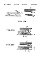
- FIGS. 11A, 11B, 11C and 11D are sections for explaining further example of the foregoing engagement
- FIG. 12 is a section of an engaging portion in the engagement of FIGS. 11A to 11D;
- FIG. 13 is a section showing a coupling portion with an ink supply needle or so forth in the foregoing embodiment of the ink tank;
- FIG. 14 is an enlarged section of the foregoing engaging portion
- FIGS. 15A and 15B are sections for explaining an appropriate internal diameter in the foregoing coupling portion
- FIG. 16 is a front elevation of an end portion of the ink tank having the foregoing coupling portion
- FIG. 17 is a section for explaining connection between the foregoing embodiment of the ink tank and the supply needle;
- FIG. 18 is a section for explaining connection between the foregoing embodiment of the ink tank and the supply needle;
- FIG. 19 is a section for explaining connection between the foregoing embodiment of the ink tank and the supply needle;
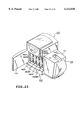
- FIG. 20 is an exploded perspective view showing another embodiment of the ink tank according to the present invention.
- FIG. 21 is a perspective view of respective parts forming the ink coupling portion in the ink tank shown in FIG. 20;
- FIG. 22 is a perspective view showing a label printer having the ink tank, to which the present invention is applied.
- FIG. 23 is a perspective view of the printer as viewed from the front side.
- FIG. 3 is an exploded perspective view showing one embodiment of an ink cartridge according to the present invention.
- the reference numeral 11 denotes an ink container and 12 denotes a lid of the ink container 11. These components forms an ink storage chamber 1.
- the reference numeral 13 denotes a waste ink container, in which an absorbing body 14 is housed. The absorbing body 14 is for absorbing and maintaining ink collected in the waste ink container 13.
- a waste ink lid 15 is mounted on the waste ink container housed therein the absorbing body 14. By this, a waste ink storage chamber is formed.
- the lid 12 is mounted by way of ultrasonic welding.
- the waste ink container 13 and the waste ink lid 15 are assembled by way of ultrasonic welding.
- housings 20 defining communication passages are provided, respectively.
- a dome shaped elastic body 16 is assembled to each of the communication passages.
- a crown body 17 is further assembled.
- a coupling portion with the apparatus main body for flowing the ink and so forth is formed.
- the ink container 11 and the waste ink container 13 are engaged and integrated by engaging portions 18 and engaging claws 19 as discussed later, to form an ink tank, namely, an ink cartridge.
- FIG. 4 according to flow of an ink cartridge production process, production of the shown embodiment of the ink tank will be discussed.
- the ink container 11 and the lid 12 thereof the waste ink container 13, the waste ink lid 15 and the crown body 17, the components preliminarily formed as independent parts by injection molding are employed.
- the elastic body 16 is a rubber material in the shown embodiment, a molded rubber or one formed by injection molding or so forth may be employed.
- the absorbing body 14 one formed by clicking a piled paper or so forth having absorptivity by simply pressing. It should be noted that as the material of the elastic body 16, an elastomer can also be employed.
- the ink container 11 and the lid 12 are assembled by way of ultrasonic welding. At this time, since the ink container 11 and the lid 12 are constructional components to which the ink is directly filled, it is desirable to assemble after washing if required.
- leak check is performed for verifying condition of welding portion of the assembled ink container 11 and the lid 12. This can be done by using one of two housings (see FIG. 3) as a pressure detecting hole, pressurizing the interior space via the other and performing check whether the internal pressure is held unchanged for a given period. It should be noted that if the welding per se is stable, it is possible to perform the leak check for all but for some as samples or not to perform the leak check.
- the absorbing body 14 is housed within the waste ink container 13, and (4) the waste ink lid 15 is assembled to the waste ink container 13 by ultrasonic welding. (5) Even in this case, leak check of the welding portion is performed if required. It should be noted that, even in this case, pressurization of the internal space may be performed via the atmosphere communication hole 36 (see FIG. 3).
- the container 11 is set in an ink filler machine with orienting the side where the housing 20 of the ink container 11 is provided upwardly. Then, using one of the housing 20 in the lid 12 as filler opening and the other housing as ventilation opening for the internal air, necessary amount of ink ius supplied. (8) Thereafter, weight check or so forth is performed as verification of filled amount of the ink as required.
- the ink cartridge is completed. It should be noted that the foregoing flow is merely one example, and it is the matter of course that the assembling operation is performed in the shown order.
- FIG. 5 shows a section of the completed ink cartridge.
- the process step for assembling the ink container 11 and the lid 12 and the process step for housing the absorbing body 14 within the waste ink container 13 and assembling the waste ink lid 15 are performed in the completely separate process steps. Therefore, it can be successfully avoided to contaminate the ink container 11 particularly by the debris of the absorbing body 14.
- weld materials such as polypropylene (P. P.), polybutylene terephthalate (P. B. T.) or so forth which have high gas barrier property and thus is ideal as material for the ink tank container but is difficulty to be practically used for low weldability.
- the materials can be preferably used as a constructional material for an ink tank.
- the PP material is low in material cost and have transparency, it would be convenient for the user to form the tank container with the PP material for capability of visually checking a remaining amount of the ink.
- a bottom surface 11a of the ink container is formed to be lower at the coupling portion side in the condition where the ink container 11 is integrated with the waste ink container 13.
- the ink can be concentrated at the side of the coupling portion 20B.
- the gradient of the bottom surface can be formed by utilizing draft angle upon formation of the ink container 11 by way of injection molding.
- the ink when the collected waste ink overflows, the ink always flows frontwardly, namely toward the side of the coupling portion 20C. Therefore, the overflow ink may not flow to handle of the waste ink lid 15, to which the user's hand may touch.
- the ceiling wall 13a of the waste ink container is lower at the side of the coupling portion 20C and a member for coupling and positioning with the ink container 11 is provided on the upper surface of the waste ink container 13 as shown in FIG. 6 to thus form a guide portion for the overflown ink.
- the reference numeral 44 denotes a cut out portion required in relation to a mold upon formation of the engaging claws at the rear end side of the waste ink container. Accordingly, in some molds for injection molding, the cut-out portion 44 becomes unnecessary. Also, the cut-out portion 44 may be covered with a label adhered in a range shown by one-dotted line in FIG. 5 to make the waste ink passage set forth above as enclosed space. By this. leakage of the ink from the cut-out portion 44 can be avoided.
- the gradient of the ceiling of the waste ink container 13 may also be formed utilizing draft angle similarly to the bottom surface 11a of the ink container 11.
- the waste ink can be certainly guided to the coupling portion side irrespective of the type of the waste ink collection system of the apparatus main body.
- the waste ink introduced toward the coupling portion side reaches a storage lower frame 140L of the apparatus main body as shown in FIG. 8. Then, the storage lower frame 140L has a tapered portion. Thus, the waste ink is finally collected to the end portion of the storage lower frame 140L.
- the ink amount reaching the predetermined amount is detected to be taken an appropriate measure, such as discharging of the waste ink or so forth.
- FIGS. 9A, 9B and 9C are enlarged section of the engaging portion 18 of the ink container 11 and the engaging claw 19 of the waste ink container 13.
- the engaging claw 19 is inserted into the engaging portion 18 in a direction of arrow A in the drawing, by coupling action of the ink container 11 and the waste ink container 13. Subsequently, by inserting motion, the engaging projection 28 of the engaging claw 19 shown in FIG. 9B tends to pass over the engaging projection 29 of the engaging portion 18. At this time, the engaging claw 19 is deflected about the base portion serving as fulcrum as shown by the drawing to pass over the engaging projection 29. In response to this, the spring portion is deflected as shown in the drawing. When the engaging projection 28 passes over the engaging projection 29, respective projections engage with recessed portions. On the other hand, the spring portion 30 acts for fixing engagement. By this, the engaging portion 18 and the engaging claw 19 are firmly engaged and fixed.
- the spring portion 30 serves for restricting the engaging claw 19 to maintain engaging condition when a force acts in a direction for releasing engaging condition. However, when a force beyond the spring force of the spring portion acts, the engaging condition may be released.
- the material 31 solidified like the adhesion is preferably a type to be solidified with time. On the other hand, it is also desirable that the material is hard after solidification, namely has low elasticity.
- the material 31 to be solidified like adhesion is not yet cured.
- the engaging projection 28 passes over the engaging projection 29, the spring portion 30 is deflected as pushed by the engaging claw 19.
- the material 31 to be solidified like adhesion is deformed, engagement between the engaging portion 18 and the engaging claw 19 is not interfered.
- the material solidified like adhesion is solidified with time between the spring portion 30 and the wall surface 32 of the container. Accordingly, after solidification, deflection of the spring portion 30 has to be restricted. Thus, disengagement of the engaging portion becomes difficult.
- the material 31 to be solidified like adhesion is not always required to be adhered to the spring portion 30 or the wall surface 32, and is required to be positioned at a position where the spring portion 30 may not be deflected. Therefore, it is obvious to those skilled in the art that such material is not limited to the adhesive.
- FIGS. 11A to 11C an embodiment where engaging projection of the engaging claw is further added is illustrated in FIGS. 11A to 11C.
- the engaging claw 19 is assembled with respect to the engaging portion 18 in the direction as shown by the arrow A in the drawing 11 (see FIG. 11A).
- the additional engaging projection 33 also passes over the end 34 of the spring portion 30 (see FIG. 1iB).
- FIG. 11C a condition where engagement is completed is established.
- the engaging projections 29 and 28 are placed in the engaged condition via the engaging projection 33.
- FIG. 12 shows a section of the engaging claw 19 shown in FIG. 11A.
- the engaging projections 33 take form as shown in FIG. 12. Then, by forming a groove 35 on the spring portion 30 corresponding to the engaging projection 33, it becomes possible to adapted without significantly varying the configuration from that shown in FIG. 9.
- positioning in the longitudinal direction upon coupling of the ink container 11 and the waste ink container 13 is done by contacting a contact portion 42 provided on the upper portion of the waste ink container 13 and a contacting portion 43 provided in the ink container 11, and by engaging the engaging portion 18 and the engaging claw 19 as set forth above.
- positioning in the direction perpendicular to the longitudinal direction is performed by the side walls of the guide members 40a and 40b of the waste ink container and contacting portions 41a and 41b of engaging member 41 provided in the ink container 11, as set forth above.
- the reference numeral 20 denotes the housing set forth above.
- the internal radius r of the housing 20 as receptacle for the elastic body 16 is substantially equal to the external radius r 1 of the elastic body 16.
- smaller radius r 1 of the elastic body 16 than the internal radius r of the housing 20 may facilitate installation, even when the r 1 is slightly greater than r, since the configuration of the elastic body 16 may be easily deformed by applying a force, no significant problem will be arisen as long as the r 1 is not excessively greater than r.
- the elastic body 16 is formed into a dome shaped configuration having a curvature R as a sole body.
- the crown body 17 is installed to cover the housing 20.
- the crown body 17 has an engaging claw 23 engageable with an engaging portion 25 at the side of the housing 20, and a pushing portion 22 for pushing the elastic body 16 in a direction substantially perpendicular to the diametrical direction of the elastic body 16.
- the reference numeral 24 denotes an opening portion for guiding the needle of the main body.
- the tip end 24a of the opening portion 24 is formed to be greater than the rear end 24b so that the needle certainly locate in the vicinity of the center of the elastic body.
- the reference numeral 26 denotes a communicating portion toward inside of the container.
- FIG. 14 there is illustrated a condition where the foregoing three parts are assembled.
- the elastic body 16 before installation of the crown body 17 is in the condition shown by broken line, whereas the elastic body 16 is depressed by the pushing portion 22 of the crown body 17 in a direction substantially perpendicular to the diametrical direction to be installed within the housing 20 in a form as illustrated by the solid line.
- the length L in the direction of section of the elastic body 16 in the independent form is 2r ⁇ L.
- the elastic body 16 Since the expanding force is restricted by the housing, the elastic body 16 is held in a condition compressed in the diametrical direction by the housing 20 and the crown body 17. By this, even when the needle 27 is pierced and removed, the elastic body 16 is returned to the initial condition to close the hole formed by piercing of the needle 27. Therefore, leakage of the ink or waste ink as the content can be successfully prevented.
- relationship between the opening diameter 24b at the. side of the pushing portion 22 of the opening portion 24 of the crown body 17 and the internal diameter 26a of the communicating portion 26 at the housing side is 24b ⁇ 26a.
- the opening diameter 24b In view of depression of the elastic body 16 with the pushing portion 22 of the crown body 17, it is desirable to form the opening diameter 24b as small as possible, whereas in relation to the needle 27, it is desirable to make the opening diameter 24b as large as possible. Accordingly, when the opening diameter 24b is reduced as small as possible, in order to effectively utilize the opening diameter 24b sufficiently, in consideration of the position error between the crown body 17 and the housing 20 or so forth, the internal diameter of the communicating portion 26 at the side of the housing 20 is made equal to or greater than that of the elastic body. If the dimensional relationship is opposite, the needle 27 passing the opening portion 24 of the crown body 17 and piercing the elastic body, may abut onto the housing to make further piercing impossible.
- the elastic body 16 may be depressed into the housing when the needle is pierced and may not return to the initial position even after removing of the needle 27. While fluctuating depending upon thickness of the elastic body 16 or size of the needle 27, based on the results of experiments, when the thickness of the elastic body 16 is about 3 mm and the diameter of the needle 27 is 1.2 mm, the internal diameter 26a is desirably less than or equal to ⁇ 5 mm.
- the mark B in evaluation of the ink leakage represents the case where ink leakage is caused after removing the needle when permanent strain is caused in the elastic body 16 by maintaining with piercing the needle 27 under the environment of 60° C. or so forth.
- the mark B in evaluation of needle piercing ability represents, in consideration of convenience of use, a level to be judged too hard for ladies or those having small power.
- the shown embodiment of the ink tank has a construction as shown in FIG. 5, and when the ink in the ink container is consumed out, a needle for ventilating internal air is pierced to one of the coupling portion, and ink is re-filled to the other by means of injector or so forth. Furthermore, by providing new parts of the crown body 17 and the elastic body 16 and exchange with the old ones, completely equivalent performance to the initial condition can be recovered.
- the material of the waste ink container to be a material which permits to observe the ink absorption amount in the waste ink container in certain extent, e.g. chemically stable material to the ink, such as polyethylene, polypropylene or so forth and thus being difficult to be attached by the ink, and being capable to permit observation of the condition of the ink in the certain extent, accumulation of the waste ink in the excess amount in the waste ink absorbing body by repeating re-filling of the ink to cause overflow from the waste ink container can be successfully prevented.
- chemically stable material to the ink such as polyethylene, polypropylene or so forth and thus being difficult to be attached by the ink
- the ink may flow toward the coupling portion as set forth above, if the ink sensor as set forth above is provided, it is possible to eliminate possibility using the ink tank in the condition where the waste ink container is filled up with the waste ink and thus is causing overflow.
- FIG. 16 is a front elevation of the shown embodiment of the ink cartridge as viewed from the of the coupling portion side.
- Respective of the coupling portions 20A, 20B and 20C are respectively provided at predetermined positions from two reference surfaces. These reference surfaces are adapted to contact with predetermined portions when the ink cartridge 10 is loaded in the apparatus main body for enable positioning relative to the supply needle and respective coupling portions of the main body side.
- the coupling portion 20A in the uppermost position is provided with offset toward the reference surface side in comparison with other to coupling portions 20B and 20C.
- a space defined by offset of this coupling portion 20A a convex portion 48 is formed.
- the convex portion 48 is formed to have a height substantially equal to the front end face of the ink cartridge (see FIG. 5) and performs the following function.
- FIGS. 17 to 19 are illustrations for explaining functions of the convex portion 48 shown in FIGS. 5 and 16 and are sections showing positional relationship of the needle 275C of a supply needle unit 275 and the ink cartridge 10 upon loading.
- a valve 275A is biased by means of a spring 275B to maintain the communication passage in closed condition.
- the lever 275D of the supply needle unit 275 reaches to contact with the convex portion 48 of the ink cartridge 10.
- the portion having the communication hole at the tip end of the needle 275C already pieces through the elastic body 16 and is located within the ink cartridge.
- the lever 275D is just come into contact with the convex portion 48 of the ink cartridge.
- the depression force from the ink cartridge is just about act. Accordingly, at this time, the valve 275A maintains the communication passage in closed condition.
- the supply needle unit 275 for circulating the ink to the ink cartridge from a not shown sub-tank at first enters the portion of the communication opening of the needle 275C into the ink cartridge associating with the insertion operation of the ink cartridge 10. Subsequently, the valve 275A is opened/ In other words, the relationship between the length of the lever 275D and the length of the needle 275C is determined to assure the foregoing series of operation.
- the convex portion 48 is provided for valve operation of the supply needle of the apparatus main body side.
- projecting of the convex portion 48 into the recessed portion of the lid 12 of the ink container is for facilitating production of the coupling portions 20A and 20B as set forth above.
- the elastic body 16 is mounted in the housing 20, and the crown body 17 is further mounted. Mounting operation is facilitated since the surrounding thereof is the space of the recessed portion. Therefore, the convex portion 48 to abut against the lever 275D as set forth above is projected into the recessed portion.
- the ink supply needle 275C as set forth above is for returning the ink recirculated from the not shown sub-tank to the ink storage portion of the ink cartridge, and thus passes through the elastic body 16 at the coupling portion 20A.
- Other coupling portion 20B connects the supply needle for performing ink supply to the apparatus main body.
- the coupling portion 20C of the waste ink container is designed to connect the needle for introducing the waste ink into the waste ink storage chamber.
- the needles of the supply needle units connected with the coupling portions 20B and 20C do not have the valve construction as set forth above.
- the reference numeral 20 denotes the cylindrical housing. Within this housing 20, an elastic body receptacle portion 20a for receiving therein the elastic body 16. An internal radius r of the elastic body receptacle portion 20a and the external radius r 1 of the elastic body 16 are set at substantially equal dimensions. Here, it would facilitate assembling when the external radius r 1 of the elastic body 16 is smaller than the internal radius r of the elastic body receptacle portion 20a. However, conversely, even when r 1 is slightly greater than r, since the configuration of the elastic body 16 may be easily varied by externally applying a force. Therefore, no problem will be arisen as long as the r 1 is not excessively great.
- the elastic body 16 is in dome shaped configuration having curvature R as independent body, as can be clear from FIG. 21.
- the crown body 17 as fixing member may be engaged and fixed.
- the crown body 17 is substantially cylindrical configuration and has a plurality of (two out of three are illustrated in FIG. 21) claw portions 23.
- grooves 39 serving as engaging portion for guiding the claw portions 23 and engaging therewith are provided on the outer periphery portion of the housing 20.
- the groove 39 generally comprises a first groove portion 39a downwardly extending from the upper end of the outer periphery portion of the housing 20 along the axis of the housing 20, and a second groove portion 39b extending in circumferential direction from the lower portion of the first groove portion 39a.
- a stopper portion 37 is provided for preventing overrunning in rotation of the crown body 17. Also, on the upper edge portion of the second groove portion 39b, projection type engaging portion 38 is provided for preventing the claw portion 23 from returning toward the first groove portion 39a.
- the pushing portion 22 for depressing the elastic body 16 housed within the elastic body receptacle portion 20a of the housing to close the cylindrical hole 26, is provided at inner side of the claw portions 23 and higher position than the claw portions.
- the elastic body 16 is elastically deformed by depression in the direction substantially perpendicular to the diametrical direction of the elastic body 16.
- the crown body 17 is rotated in circumferential direction of the housing 20 (clockwise direction in FIG. 21) until abutting against the stopper portion 37.
- the claw portions 23 is guided into the second groove portions 39b beyond the engaging portion 38.
- the claw portions 23 are upwardly urged onto the upper edge portions of the second groove body 39b by the restoring force of the elastically deformed elastic body 16.
- the pushing portion 22 of the crown body 17 and the elastic body 16 are in contact with each other with in slidable state at low friction. Therefore, torsional force may not be created in the elastic body 16 by rotation of the crown body 17.
- an elastic component of the elastic restoration force along the direction of the second groove portion 39b due to torsional force exerted is small, engagement of the upper edge portion of the second groove portion 39b to the claw portion 23 may not be released by the restoring force of the elastic body 16.
- the claw portion 23 engages with the engaging portion 38 of the second groove portion 39b to complete installation of the crown body 17 to the housing 20.
- the claw portion 23 of the crown body 17 set forth above is biased upwardly toward the upper edge portion of the second groove portion 39b so as not to pass over the projection form engaging portion 38.
- the crown body 17 may not drop out from the housing 20 by vibration, impact of dropping, environmental condition, such as heat cycle or so forth. Therefore, closure of the cylindrical hole 26 of the ink tank by the elastic body 16 in the housing 20 may not be released easily. Accordingly, in the shown embodiment, the ink tank having high reliability can be provided without any ink leakage.
- no force in the direction for expanding the diameter may be applied to the crown body 17. Therefore, even when non-expandable material of the crown body 17 and high rigidity material of the housing 20 are combined, assembling is easy. Also, without applying significant stress on the crown body, a coupling portion having high reliability can be provided.
- the reference numeral 24 denotes an opening portion for guiding the needle of the main body.
- the tip end 24a is formed wider than the rear end 24b so that the needle may certainly be positioned substantially at the center of the elastic body with respect to position error to the needle of the main body side.
- the foregoing pushing portion 22 is formed.
- the reference numeral 26 denotes a communicating portion (cylindrical hole) formed at the center portion of the elastic body receptacle portion 20a of the housing for establishing communication with the interior of the container.
- a distance from the surface of the ink container to the upper edge portion of the second groove portion 39b of the housing is set at 2.3 mm, for example.
- the height of the claw portion 23 of the crown body 17 is 1.7 mm, for example.
- maximum depression amount of the crown body 17 into the housing 20 becomes about 0.6 mm.
- a projecting amount of the engaging portion 38 of the housing 20 is 0.2 mm, for example, approximately 0.4 mm of gap is formed between the claw portion 23 and the engaging portion 38 at the maximum depression amount.
- the coupling portion preferably satisfies the similar condition to the former embodiment.
- FIG. 22 is a perspective view of a label printer as an ink-jet printing apparatus, to which the present invention is applied, in a condition where a cover 111 of a roll paper supply unit 101 is removed and a printing head 102 is opened by pivoting upwardly
- FIG. 23 is a perspective view showing a condition where a front cover 113 of an ink cartridge portion 103 is opened.
- a roll 126 on which a roll paper 124 to be housed within the roll paper supply unit 101 is wound around, is mounted on two driving rollers 301 (one is not shown) provided on the bottom portion of the unit 101.
- the outer periphery side of the roll 126 and driving roller 301 are held in contact associated with depression force by own weight of the roll paper 124.
- the driving roller 301 or so forth by driving force of not shown motor the roll paper 124 at the outermost periphery is fed separating from the roll paper at the inside.
- Feeding of the roll paper is performed substantially irrespective of transportation by a roll paper feeding mechanism 104 (detail thereof is not shown) between a printer head portion 102 and a cartridge receptacle portion 103. Accordingly, in order to adjust feeding between two portions, in the foregoing roll paper supply, feeding of the roll paper is controlled to form a loop (slack, not shown in FIG. 22) serving as a buffer. Namely, when a loop sensor (not shown) fails to detect a loop by feeding in the feeding mechanism 104, the foregoing driving roller is driven to perform feeding of the roll paper with forming the loop.
- the paper guide 131 is provided for sliding in the width direction of the stored roll 126. Namely, upon storing the roll paper, the paper guide 131 is slide in a magnitude greater than the width of the roll paper 124 to mount the roll 126 on the driving roll. Thereafter, the paper guide 131 is slide to the width of the roll 126 to abut a part onto the core member 125 of the roll 126. By this, upon supplying the roll paper 124, vibration of the roll paper 124 in the width direction at the upstream side of the driving roll in the feeding direction can be restricted with permitting a given fine vibration. It should be noted that, in the paper guide 131, a stopper 316 for fixing the slide position of the paper guide is provided.
- an obliquely feeding unit 128 In the roll paper feeding path, in the vicinity of the inlet of the feeding path by the feeding mechanism 104, an obliquely feeding unit 128 is provided.
- the obliquely feeding unit 128 includes two obliquely feeding rollers (not shown) contacting with the lower surface of the roll paper 124 and obliquely feeding rolls 129 and 130 opposing to the obliquely feeding rollers and contacting with the upper surface of the roll paper 124.
- Two obliquely feeding rollers comprises driving roller opposes with the obliquely feeding roll 130 and is driven by driving force from the side of the feeding mechanism, and a driven roller opposing to the obliquely feeding roll 129 and is not positively driven.
- Respective rollers are mounted for rotation in a direction oblique to the feeding direction of the roll paper (rotation shaft lies oblique to the direction perpendicular to the feeding direction).
- the obliquely feeding rolls 129 and 130 are also mounted in oblique relative to the feeding direction similarly to the obliquely feeding rollers. It is possible that by these obliquely feeding rollers and the obliquely feeding rolls 129 and 130, a feeding force in oblique direction is applied to the roll paper to be fed to depress onto predetermined guide at the back side in the drawing. As a result, since the roll paper 124 is fed with restriction of the feeding direction to the predetermined direction, good performance in feeding can be obtained without causing deflection of the feeding direction.
- the roll paper feeding mechanism 104 provided between the printing head portion 102 and the cartridge receptacle portion 103 is neglected from illustration in FIG. 23.
- the roll paper feeding mechanism 104 is constructed with a plurality of belts arranged lower side of the roll paper 124 in the drawing (accordingly arranged at upper surface of the cartridge receptacle portion 103), rollers provided at upstream side and downstream side in the feeding direction for driving the belts, and spur arranged on lower surface of the printing head portion 102 and driven by a predetermined belt among a plurality of belts.
- the ink cartridge receptacle portion 103 has four cartridge receptacle chambers 140Y, 140M, 140C and 14OBk corresponding to four kinds of inks of yellow (Y), magenta (M), cyan (C) and black (Bk) employed in the shown embodiment of the label printer.
- shutters 142Y, 142M, 142C and 142Bk for substantially shielding the inside of the receptacle chambers are provided. These shutters are pivotally supported at the upper portion so as to prevent the user from erroneously inserting hand inside of the receptacle chamber and contacting with the ink supply needle.
- the ink tank of low cost and stable performance can be easily supplied without requiring any expensive apparatus.
- the elastic body since assembling of the elastic body is easy, it is possible to assemble even after filing of the ink to increase freedom in setting of the process steps. Furthermore, damaging of the elastic body by the injection needle upon injection of the ink can be resolved to improve reliability. On the other hand, since no force for expanding diameter will be exerted on the crown body, even in the combination wherein the crown body is formed with a non-expandable material and the housing is formed with high rigidity material, assembling can be done easily, and highly reliable coupling portion can be provided without causing significant stress in the crown body.
- the ink tank which has good needle piercing and releasing property and to certainly close after removing of the needle.
Landscapes
- Engineering & Computer Science (AREA)
- Manufacturing & Machinery (AREA)
- Ink Jet (AREA)
- Packages (AREA)
- Inks, Pencil-Leads, Or Crayons (AREA)
Applications Claiming Priority (6)
| Application Number | Priority Date | Filing Date | Title |
|---|---|---|---|
| JP7-237461 | 1995-09-14 | ||
| JP7-237462 | 1995-09-14 | ||
| JP23746295A JP3133929B2 (ja) | 1995-09-14 | 1995-09-14 | インクタンクおよびインクジェット記録装置 |
| JP23746195A JP3215022B2 (ja) | 1995-09-14 | 1995-09-14 | インクタンク、インクタンクの製造方法およびインクジェット記録装置 |
| JP7-266040 | 1995-10-13 | ||
| JP26604095A JP3174252B2 (ja) | 1995-10-13 | 1995-10-13 | インクタンクおよびその製造方法 |
Publications (1)
| Publication Number | Publication Date |
|---|---|
| US6132036A true US6132036A (en) | 2000-10-17 |
Family
ID=27332470
Family Applications (1)
| Application Number | Title | Priority Date | Filing Date |
|---|---|---|---|
| US08/711,948 Expired - Lifetime US6132036A (en) | 1995-09-14 | 1996-09-06 | Ink tank, production process of ink tank and ink-jet printing apparatus |
Country Status (8)
| Country | Link |
|---|---|
| US (1) | US6132036A (de) |
| EP (2) | EP1177905B1 (de) |
| KR (1) | KR100215499B1 (de) |
| CN (2) | CN1091412C (de) |
| AT (2) | ATE311296T1 (de) |
| AU (1) | AU718867B2 (de) |
| DE (2) | DE69635529T2 (de) |
| SG (2) | SG91369A1 (de) |
Cited By (24)
| Publication number | Priority date | Publication date | Assignee | Title |
|---|---|---|---|---|
| US6481839B1 (en) * | 1998-05-29 | 2002-11-19 | Citizen Watch Co., Ltd. | Fluid material reservoir |
| US20020180826A1 (en) * | 2001-05-31 | 2002-12-05 | Yukuo Yamaguchi | Liquid discharge recording head, liquid discharge recording apparatus, and method for producing stopper member for liquid discharge recording head |
| US6554411B1 (en) * | 1999-09-03 | 2003-04-29 | Canon Kabushiki Kaisha | Liquid container and printing apparatus to which the liquid container is mounted |
| US6609788B2 (en) * | 2000-03-31 | 2003-08-26 | Canon Kabushiki Kaisha | Liquid container cartridge, liquid container and recording apparatus |
| US6619790B1 (en) * | 2002-03-11 | 2003-09-16 | Monitek Electronics Limited | Ink-jet printer cartridge upper cover |
| US20040263590A1 (en) * | 2003-04-25 | 2004-12-30 | Kiyomitsu Kudo | Ink cartridge |
| US20050062815A1 (en) * | 2003-07-10 | 2005-03-24 | Fuji Xerox Co., Ltd. | Ink supplying apparatus and recording apparatus |
| US6877848B2 (en) | 2001-09-28 | 2005-04-12 | Canon Kabushiki Kaisha | Liquid container, connection unit for liquid container, and ink jet recording apparatus |
| US20070229631A1 (en) * | 2006-03-31 | 2007-10-04 | Brother Kogyo Kabushiki Kaisha | Protector for ink cartridge container |
| US20070229582A1 (en) * | 2006-03-31 | 2007-10-04 | Brother Kogyo Kabushiki Kaisha | Protection device for an ink cartridge storage unit |
| US20070229625A1 (en) * | 2006-03-31 | 2007-10-04 | Brother Kogyo Kabushiki Kaisha | Protection Device For An Ink Cartridge Storage Unit |
| US20070229620A1 (en) * | 2006-03-31 | 2007-10-04 | Brother Kogyo Kabushiki Kaisha | Protector For Ink Cartridge Container |
| US20080165232A1 (en) * | 2007-01-10 | 2008-07-10 | Kenneth Yuen | Ink cartridge |
| US20080225094A1 (en) * | 2003-05-09 | 2008-09-18 | Seiko Epson Corporation | Liquid-jetting device |
| US20080239039A1 (en) * | 2003-08-08 | 2008-10-02 | Taku Ishizawa | Liquid container |
| JP2012060791A (ja) * | 2010-09-09 | 2012-03-22 | Yazaki Corp | 取付物の固定構造 |
| US20120182363A1 (en) * | 2011-01-14 | 2012-07-19 | Seiko Epson Corporation | Flow path member, liquid ejecting head, and liquid ejecting apparatus |
| US20120234436A1 (en) * | 2011-03-18 | 2012-09-20 | Seiko Epson Corporation | Waste liquid container and liquid consumption apparatus |
| US20130250012A1 (en) * | 2012-03-21 | 2013-09-26 | Michael Renejane Larrobis, JR. | Fluid container |
| US20140184709A1 (en) * | 2012-12-27 | 2014-07-03 | Qisda Optronics (Suzhou) Co., Ltd. | Ink tank and printer therewith |
| US9411299B2 (en) | 2005-09-22 | 2016-08-09 | Ricoh Company, Ltd. | Lubricant supply device, image forming apparatus, and pressing device |
| US10357972B2 (en) * | 2015-04-14 | 2019-07-23 | Canon Kabushiki Kaisha | Printer and waste pack for use in printer |
| US20210131591A1 (en) * | 2019-10-31 | 2021-05-06 | Seiko Epson Corporation | Flow Path Member, Flow Path Unit, And Liquid Ejecting Apparatus |
| US11007785B2 (en) | 2018-09-18 | 2021-05-18 | Seiko Epson Corporation | Waste liquid container and attachment |
Families Citing this family (8)
| Publication number | Priority date | Publication date | Assignee | Title |
|---|---|---|---|---|
| JP3167598B2 (ja) * | 1995-10-13 | 2001-05-21 | キヤノン株式会社 | インクタンクおよびインクジェット記録装置 |
| US6908182B2 (en) * | 2000-01-31 | 2005-06-21 | Seiko Epson Corporation | Ink cartridge and ink jet printer |
| JP3796439B2 (ja) * | 2001-02-09 | 2006-07-12 | キヤノン株式会社 | 液体収納容器 |
| EP1498272A1 (de) * | 2003-07-18 | 2005-01-19 | Seiko Epson Corporation | Flüssigkeitsbehälter |
| CN100564043C (zh) * | 2003-07-18 | 2009-12-02 | 精工爱普生株式会社 | 液体容器 |
| JP5162652B2 (ja) * | 2010-12-20 | 2013-03-13 | 富士ゼロックス株式会社 | 液体供給装置 |
| CN105269976B (zh) * | 2015-11-30 | 2017-10-27 | 珠海格美达科技有限公司 | 分体式墨盒生产系统及其生产工艺 |
| CN109318596B (zh) * | 2017-07-31 | 2021-04-30 | 兄弟工业株式会社 | 液体消耗装置及液体消耗系统 |
Citations (28)
| Publication number | Priority date | Publication date | Assignee | Title |
|---|---|---|---|---|
| US4180173A (en) * | 1977-12-13 | 1979-12-25 | Raychem Corporation | Tamper-proof closure system |
| DE3316969A1 (de) * | 1982-05-10 | 1983-11-10 | Canon K.K., Tokyo | Tintenspeicher |
| DE3220620A1 (de) * | 1982-06-01 | 1983-12-01 | Olympia Werke Ag, 2940 Wilhelmshaven | Auffangbehaelter fuer verlusttinte in tintenschreibwerken |
| JPS6154942A (ja) * | 1984-08-27 | 1986-03-19 | Konishiroku Photo Ind Co Ltd | インク貯蔵器 |
| WO1988005411A1 (en) * | 1987-01-15 | 1988-07-28 | Rexinell Ab | Sealing of containers |
| JPH0220350A (ja) * | 1988-07-08 | 1990-01-23 | Canon Inc | インクジェット記録装置 |
| WO1991004156A1 (de) * | 1989-09-13 | 1991-04-04 | Siemens Aktiengesellschaft | Entsorgungsbehälter für verlustflüssigkeit in tintenschreibeinrichtungen |
| US5126767A (en) * | 1984-02-09 | 1992-06-30 | Canon Kabushiki Kaisha | Ink tank with dual-member sealing closure |
| US5155502A (en) * | 1989-01-13 | 1992-10-13 | Canon Kabushiki Kaisha | Ink-jet cartridge |
| US5156472A (en) * | 1984-05-22 | 1992-10-20 | Seiko Epson Corporation | Dot matrix printer supply system having ink absorbing member filled under reduced pressure |
| EP0546832A2 (de) * | 1991-12-11 | 1993-06-16 | Canon Kabushiki Kaisha | Schlitten für Tintenstrahlaufzeichnungsgerät |
| US5221935A (en) * | 1990-02-15 | 1993-06-22 | Canon Kabushiki Kaisha | Waste ink receiving cartridge and ink recording apparatus using said cartridge |
| EP0553535A1 (de) * | 1992-01-28 | 1993-08-04 | Seiko Epson Corporation | Tintenvorratspatrone und Behälter dafür |
| EP0559206A2 (de) * | 1992-03-06 | 1993-09-08 | Canon Kabushiki Kaisha | Behälter für verbrauchbare Stoffe, sein Verpackungsmaterial und Verfahren zu seiner Sammlung |
| US5270739A (en) * | 1991-01-25 | 1993-12-14 | Canon Kabushiki Kaisha | Liquid container having an elastic dome-shaped pressure control device with a slit |
| JPH06963A (ja) * | 1992-06-19 | 1994-01-11 | Canon Inc | インクジェット記録装置 |
| WO1994003373A1 (en) * | 1992-08-07 | 1994-02-17 | The West Company, Incorporated | Needleless access stopper |
| US5365260A (en) * | 1991-06-19 | 1994-11-15 | Canon Kabushiki Kaisha | Ink supply device with elastic valve for liquid supplying slit |
| EP0631874A2 (de) * | 1993-06-29 | 1995-01-04 | Canon Kabushiki Kaisha | Tintenbehälter, Tintenstrahlpatrone mit Tintenbehälter und Tintenstrahlgerät ausgestatted damit |
| EP0635373A1 (de) * | 1993-07-20 | 1995-01-25 | Canon Kabushiki Kaisha | Tintenstrahlaufzeichnungsgerät, welches eine Farbkartusche mit einem tinteninduzierenden Element verwendet |
| US5400573A (en) * | 1993-12-14 | 1995-03-28 | Crystal; Richard G. | Kit and method for opening, refilling and sealing a cartridge |
| US5405001A (en) * | 1994-04-29 | 1995-04-11 | Clinetics Corporation | Removable and pierceable activation closure for two-compartment vial |
| DE4344746A1 (de) * | 1993-12-28 | 1995-06-29 | Bowa Bosse & Wagner Ohg | Vorrichtung zum dichten Transportieren und Aufbewahren einer mit Tinte gefüllten Patrone für einen Tintenstrahldrucker |
| US5444473A (en) * | 1990-11-15 | 1995-08-22 | Canon Kabushiki Kaisha | Ink jet recording apparatus |
| US5453772A (en) * | 1991-06-19 | 1995-09-26 | Canon Kabushiki Kaisha | Liquid container with bladder-like member and liquid path along an interior container wall |
| US5500664A (en) * | 1991-01-25 | 1996-03-19 | Canon Kabushiki Kaisha | Ink jet recording apparatus and detachably mountable ink jet cartridge |
| US5502479A (en) * | 1992-06-16 | 1996-03-26 | Canon Kabushiki Kaisha | Ink jet cartridge and ink jet apparatus having same |
| US5509140A (en) * | 1992-07-24 | 1996-04-16 | Canon Kabushiki Kaisha | Replaceable ink cartridge |
-
1996
- 1996-09-06 US US08/711,948 patent/US6132036A/en not_active Expired - Lifetime
- 1996-09-12 EP EP01125877A patent/EP1177905B1/de not_active Expired - Lifetime
- 1996-09-12 DE DE69635529T patent/DE69635529T2/de not_active Expired - Lifetime
- 1996-09-12 AT AT01125877T patent/ATE311296T1/de not_active IP Right Cessation
- 1996-09-12 KR KR1019960039564A patent/KR100215499B1/ko not_active IP Right Cessation
- 1996-09-12 AT AT96114621T patent/ATE217581T1/de active
- 1996-09-12 SG SG200103939A patent/SG91369A1/en unknown
- 1996-09-12 SG SG1996010635A patent/SG44056A1/en unknown
- 1996-09-12 DE DE69621218T patent/DE69621218T2/de not_active Expired - Lifetime
- 1996-09-12 EP EP96114621A patent/EP0791463B1/de not_active Expired - Lifetime
- 1996-09-13 CN CN96111556A patent/CN1091412C/zh not_active Expired - Fee Related
- 1996-09-13 AU AU65638/96A patent/AU718867B2/en not_active Ceased
- 1996-09-13 CN CNB011393548A patent/CN1156374C/zh not_active Expired - Fee Related
Patent Citations (29)
| Publication number | Priority date | Publication date | Assignee | Title |
|---|---|---|---|---|
| US4180173A (en) * | 1977-12-13 | 1979-12-25 | Raychem Corporation | Tamper-proof closure system |
| US4695824A (en) * | 1982-05-10 | 1987-09-22 | Canon Kabushiki Kaisha | Ink storing apparatus with a first case having plural ink tanks and second case having one ink tank and a waste ink receptacle |
| DE3316969A1 (de) * | 1982-05-10 | 1983-11-10 | Canon K.K., Tokyo | Tintenspeicher |
| DE3220620A1 (de) * | 1982-06-01 | 1983-12-01 | Olympia Werke Ag, 2940 Wilhelmshaven | Auffangbehaelter fuer verlusttinte in tintenschreibwerken |
| US5126767A (en) * | 1984-02-09 | 1992-06-30 | Canon Kabushiki Kaisha | Ink tank with dual-member sealing closure |
| US5156472A (en) * | 1984-05-22 | 1992-10-20 | Seiko Epson Corporation | Dot matrix printer supply system having ink absorbing member filled under reduced pressure |
| JPS6154942A (ja) * | 1984-08-27 | 1986-03-19 | Konishiroku Photo Ind Co Ltd | インク貯蔵器 |
| WO1988005411A1 (en) * | 1987-01-15 | 1988-07-28 | Rexinell Ab | Sealing of containers |
| JPH0220350A (ja) * | 1988-07-08 | 1990-01-23 | Canon Inc | インクジェット記録装置 |
| US5155502A (en) * | 1989-01-13 | 1992-10-13 | Canon Kabushiki Kaisha | Ink-jet cartridge |
| WO1991004156A1 (de) * | 1989-09-13 | 1991-04-04 | Siemens Aktiengesellschaft | Entsorgungsbehälter für verlustflüssigkeit in tintenschreibeinrichtungen |
| US5221935A (en) * | 1990-02-15 | 1993-06-22 | Canon Kabushiki Kaisha | Waste ink receiving cartridge and ink recording apparatus using said cartridge |
| US5444473A (en) * | 1990-11-15 | 1995-08-22 | Canon Kabushiki Kaisha | Ink jet recording apparatus |
| US5270739A (en) * | 1991-01-25 | 1993-12-14 | Canon Kabushiki Kaisha | Liquid container having an elastic dome-shaped pressure control device with a slit |
| US5500664A (en) * | 1991-01-25 | 1996-03-19 | Canon Kabushiki Kaisha | Ink jet recording apparatus and detachably mountable ink jet cartridge |
| US5453772A (en) * | 1991-06-19 | 1995-09-26 | Canon Kabushiki Kaisha | Liquid container with bladder-like member and liquid path along an interior container wall |
| US5365260A (en) * | 1991-06-19 | 1994-11-15 | Canon Kabushiki Kaisha | Ink supply device with elastic valve for liquid supplying slit |
| EP0546832A2 (de) * | 1991-12-11 | 1993-06-16 | Canon Kabushiki Kaisha | Schlitten für Tintenstrahlaufzeichnungsgerät |
| EP0553535A1 (de) * | 1992-01-28 | 1993-08-04 | Seiko Epson Corporation | Tintenvorratspatrone und Behälter dafür |
| EP0559206A2 (de) * | 1992-03-06 | 1993-09-08 | Canon Kabushiki Kaisha | Behälter für verbrauchbare Stoffe, sein Verpackungsmaterial und Verfahren zu seiner Sammlung |
| US5502479A (en) * | 1992-06-16 | 1996-03-26 | Canon Kabushiki Kaisha | Ink jet cartridge and ink jet apparatus having same |
| JPH06963A (ja) * | 1992-06-19 | 1994-01-11 | Canon Inc | インクジェット記録装置 |
| US5509140A (en) * | 1992-07-24 | 1996-04-16 | Canon Kabushiki Kaisha | Replaceable ink cartridge |
| WO1994003373A1 (en) * | 1992-08-07 | 1994-02-17 | The West Company, Incorporated | Needleless access stopper |
| EP0631874A2 (de) * | 1993-06-29 | 1995-01-04 | Canon Kabushiki Kaisha | Tintenbehälter, Tintenstrahlpatrone mit Tintenbehälter und Tintenstrahlgerät ausgestatted damit |
| EP0635373A1 (de) * | 1993-07-20 | 1995-01-25 | Canon Kabushiki Kaisha | Tintenstrahlaufzeichnungsgerät, welches eine Farbkartusche mit einem tinteninduzierenden Element verwendet |
| US5400573A (en) * | 1993-12-14 | 1995-03-28 | Crystal; Richard G. | Kit and method for opening, refilling and sealing a cartridge |
| DE4344746A1 (de) * | 1993-12-28 | 1995-06-29 | Bowa Bosse & Wagner Ohg | Vorrichtung zum dichten Transportieren und Aufbewahren einer mit Tinte gefüllten Patrone für einen Tintenstrahldrucker |
| US5405001A (en) * | 1994-04-29 | 1995-04-11 | Clinetics Corporation | Removable and pierceable activation closure for two-compartment vial |
Cited By (42)
| Publication number | Priority date | Publication date | Assignee | Title |
|---|---|---|---|---|
| US6481839B1 (en) * | 1998-05-29 | 2002-11-19 | Citizen Watch Co., Ltd. | Fluid material reservoir |
| US6554411B1 (en) * | 1999-09-03 | 2003-04-29 | Canon Kabushiki Kaisha | Liquid container and printing apparatus to which the liquid container is mounted |
| US6609788B2 (en) * | 2000-03-31 | 2003-08-26 | Canon Kabushiki Kaisha | Liquid container cartridge, liquid container and recording apparatus |
| US20020180826A1 (en) * | 2001-05-31 | 2002-12-05 | Yukuo Yamaguchi | Liquid discharge recording head, liquid discharge recording apparatus, and method for producing stopper member for liquid discharge recording head |
| US6880925B2 (en) | 2001-05-31 | 2005-04-19 | Canon Kabushiki Kaisha | Liquid discharge recording head, liquid discharge recording apparatus, and method for producing stopper member for liquid discharge recording head |
| US6877848B2 (en) | 2001-09-28 | 2005-04-12 | Canon Kabushiki Kaisha | Liquid container, connection unit for liquid container, and ink jet recording apparatus |
| US6619790B1 (en) * | 2002-03-11 | 2003-09-16 | Monitek Electronics Limited | Ink-jet printer cartridge upper cover |
| US7192127B2 (en) * | 2003-04-25 | 2007-03-20 | Canon Kabushiki Kaisha | Ink cartridge |
| US20070052778A1 (en) * | 2003-04-25 | 2007-03-08 | Kiyomitsu Kudo | Ink cartridge |
| US20040263590A1 (en) * | 2003-04-25 | 2004-12-30 | Kiyomitsu Kudo | Ink cartridge |
| US7556366B2 (en) * | 2003-04-25 | 2009-07-07 | Canon Kabushiki Kaisha | Ink cartridge |
| US8020977B2 (en) * | 2003-05-09 | 2011-09-20 | Seiko Epson Corporation | Liquid-jetting device |
| US20080225094A1 (en) * | 2003-05-09 | 2008-09-18 | Seiko Epson Corporation | Liquid-jetting device |
| US20050062815A1 (en) * | 2003-07-10 | 2005-03-24 | Fuji Xerox Co., Ltd. | Ink supplying apparatus and recording apparatus |
| US8668317B2 (en) | 2003-08-08 | 2014-03-11 | Seiko Epson Corporation | Liquid container |
| US8210670B2 (en) | 2003-08-08 | 2012-07-03 | Seiko Epson Corporation | Liquid container |
| US8083335B2 (en) | 2003-08-08 | 2011-12-27 | Seiko Epson Corporation | Liquid container |
| US20080239039A1 (en) * | 2003-08-08 | 2008-10-02 | Taku Ishizawa | Liquid container |
| US20110134197A1 (en) * | 2003-08-08 | 2011-06-09 | Taku Ishizawa | Liquid container |
| US9411299B2 (en) | 2005-09-22 | 2016-08-09 | Ricoh Company, Ltd. | Lubricant supply device, image forming apparatus, and pressing device |
| US7837308B2 (en) | 2006-03-31 | 2010-11-23 | Brother Kogyo Kabushiki Kaisha | Protector for ink cartridge container |
| US20070229582A1 (en) * | 2006-03-31 | 2007-10-04 | Brother Kogyo Kabushiki Kaisha | Protection device for an ink cartridge storage unit |
| US7740339B2 (en) | 2006-03-31 | 2010-06-22 | Brother Kogyo Kabushiki Kaisha | Protection device for an ink cartridge storage unit |
| US8025359B2 (en) | 2006-03-31 | 2011-09-27 | Brother Kogyo Kabushiki Kaisha | Protector for ink cartridge container |
| US20070229620A1 (en) * | 2006-03-31 | 2007-10-04 | Brother Kogyo Kabushiki Kaisha | Protector For Ink Cartridge Container |
| US20070229625A1 (en) * | 2006-03-31 | 2007-10-04 | Brother Kogyo Kabushiki Kaisha | Protection Device For An Ink Cartridge Storage Unit |
| US20070229631A1 (en) * | 2006-03-31 | 2007-10-04 | Brother Kogyo Kabushiki Kaisha | Protector for ink cartridge container |
| US7922281B2 (en) | 2006-03-31 | 2011-04-12 | Brother Kogyo Kabushiki Kaisha | Protection device for an ink cartridge storage unit |
| US20080165232A1 (en) * | 2007-01-10 | 2008-07-10 | Kenneth Yuen | Ink cartridge |
| JP2012060791A (ja) * | 2010-09-09 | 2012-03-22 | Yazaki Corp | 取付物の固定構造 |
| US20120182363A1 (en) * | 2011-01-14 | 2012-07-19 | Seiko Epson Corporation | Flow path member, liquid ejecting head, and liquid ejecting apparatus |
| US8534815B2 (en) * | 2011-01-14 | 2013-09-17 | Seiko Epson Corporation | Flow path member, liquid ejecting head, and liquid ejecting apparatus |
| US9132644B2 (en) * | 2011-03-18 | 2015-09-15 | Seiko Epson Corporation | Waste liquid container and liquid consumption apparatus |
| US20120234436A1 (en) * | 2011-03-18 | 2012-09-20 | Seiko Epson Corporation | Waste liquid container and liquid consumption apparatus |
| US9096068B2 (en) * | 2012-03-21 | 2015-08-04 | Funai Electric Co., Ltd. | Fluid container |
| US20130250012A1 (en) * | 2012-03-21 | 2013-09-26 | Michael Renejane Larrobis, JR. | Fluid container |
| US9878550B2 (en) | 2012-03-21 | 2018-01-30 | Funai Electric Co., Ltd. | Fluid container |
| US20140184709A1 (en) * | 2012-12-27 | 2014-07-03 | Qisda Optronics (Suzhou) Co., Ltd. | Ink tank and printer therewith |
| US8905531B2 (en) * | 2012-12-27 | 2014-12-09 | Qisda Optronics (Suzhou) Co., Ltd. | Ink tank and printer therewith |
| US10357972B2 (en) * | 2015-04-14 | 2019-07-23 | Canon Kabushiki Kaisha | Printer and waste pack for use in printer |
| US11007785B2 (en) | 2018-09-18 | 2021-05-18 | Seiko Epson Corporation | Waste liquid container and attachment |
| US20210131591A1 (en) * | 2019-10-31 | 2021-05-06 | Seiko Epson Corporation | Flow Path Member, Flow Path Unit, And Liquid Ejecting Apparatus |
Also Published As
| Publication number | Publication date |
|---|---|
| DE69621218T2 (de) | 2002-10-31 |
| DE69621218D1 (de) | 2002-06-20 |
| ATE217581T1 (de) | 2002-06-15 |
| AU6563896A (en) | 1997-03-20 |
| AU718867B2 (en) | 2000-04-20 |
| CN1091412C (zh) | 2002-09-25 |
| EP0791463B1 (de) | 2002-05-15 |
| CN1153707A (zh) | 1997-07-09 |
| EP1177905B1 (de) | 2005-11-30 |
| EP1177905A2 (de) | 2002-02-06 |
| EP0791463A2 (de) | 1997-08-27 |
| EP0791463A3 (de) | 1998-07-08 |
| SG44056A1 (en) | 1997-11-14 |
| ATE311296T1 (de) | 2005-12-15 |
| KR100215499B1 (ko) | 1999-08-16 |
| DE69635529T2 (de) | 2006-07-13 |
| DE69635529D1 (de) | 2006-01-05 |
| CN1358629A (zh) | 2002-07-17 |
| CN1156374C (zh) | 2004-07-07 |
| SG91369A1 (en) | 2002-09-17 |
| KR970020440A (ko) | 1997-05-28 |
| EP1177905A3 (de) | 2002-03-27 |
Similar Documents
| Publication | Publication Date | Title |
|---|---|---|
| US6132036A (en) | Ink tank, production process of ink tank and ink-jet printing apparatus | |
| EP1277584B1 (de) | Ventileinheit für Tintenbehälter | |
| US6443567B1 (en) | Liquid ejecting cartridge and recording device using same | |
| US6450631B1 (en) | Storing method of ink tank and ink jet head cartridge, and ink tank and storing container used in the same method | |
| EP0768183B1 (de) | Tintenkassette mit Tintenbehälter und Abfalltintenbehälter | |
| KR100354099B1 (ko) | 잉크 용기, 잉크 용기용 홀더, 홀더를 갖는 잉크 제트기록 장치 및 잉크 용기를 홀더에 장착하는 장착 방법 | |
| US6530654B2 (en) | Ink container, valve unit for ink container, ink jet head cartridge having ink container and ink jet recording apparatus | |
| US8025376B2 (en) | Ink cartridges | |
| AU724586B2 (en) | Liquid supply method, system, ink container, cartridge and replenishing container and head cartridge usable with system | |
| US6382783B1 (en) | Liquid supply method, capillary force generating member container used for method thereof, and liquid supply container | |
| US6467889B2 (en) | Ink tank and method of manufacture therefor | |
| US20070070147A1 (en) | Ink cartridge arrangements | |
| US7810916B2 (en) | Ink cartridges | |
| US7553007B2 (en) | Ink cartridges | |
| JPH09109414A (ja) | インクタンクおよびその製造方法 | |
| JP3215022B2 (ja) | インクタンク、インクタンクの製造方法およびインクジェット記録装置 | |
| US7775645B2 (en) | Methods of forming cartridges, such as ink cartridges | |
| US7837311B2 (en) | Ink cartridges | |
| US7682004B2 (en) | Ink cartridges | |
| JP3133929B2 (ja) | インクタンクおよびインクジェット記録装置 | |
| US20230099942A1 (en) | Liquid storage container | |
| JP2004167795A (ja) | 液体収納容器 | |
| KR20000048242A (ko) | 잉크 탱크 및 잉크 탱크 제조 방법 |
Legal Events
| Date | Code | Title | Description |
|---|---|---|---|
| AS | Assignment |
Owner name: CANON KABUSHIKI KAISHA, JAPAN Free format text: ASSIGNMENT OF ASSIGNORS INTEREST;ASSIGNORS:ABE, TSUTOMU;KOIZUMI, YUTAKA;AONO, KIYOMI;AND OTHERS;REEL/FRAME:008235/0439;SIGNING DATES FROM 19661018 TO 19961018 |
|
| STCF | Information on status: patent grant |
Free format text: PATENTED CASE |
|
| CC | Certificate of correction | ||
| FPAY | Fee payment |
Year of fee payment: 4 |
|
| FEPP | Fee payment procedure |
Free format text: PAYOR NUMBER ASSIGNED (ORIGINAL EVENT CODE: ASPN); ENTITY STATUS OF PATENT OWNER: LARGE ENTITY |
|
| FPAY | Fee payment |
Year of fee payment: 8 |
|
| FPAY | Fee payment |
Year of fee payment: 12 |