US6097125A - Magnet fixed structure for compressor motor - Google Patents
Magnet fixed structure for compressor motor Download PDFInfo
- Publication number
- US6097125A US6097125A US09/067,714 US6771498A US6097125A US 6097125 A US6097125 A US 6097125A US 6771498 A US6771498 A US 6771498A US 6097125 A US6097125 A US 6097125A
- Authority
- US
- United States
- Prior art keywords
- magnet
- paddle
- magnets
- fixed
- compressor motor
- Prior art date
- Legal status (The legal status is an assumption and is not a legal conclusion. Google has not performed a legal analysis and makes no representation as to the accuracy of the status listed.)
- Expired - Lifetime
Links
Images


Classifications
-
- H—ELECTRICITY
- H02—GENERATION; CONVERSION OR DISTRIBUTION OF ELECTRIC POWER
- H02K—DYNAMO-ELECTRIC MACHINES
- H02K1/00—Details of the magnetic circuit
- H02K1/06—Details of the magnetic circuit characterised by the shape, form or construction
- H02K1/34—Reciprocating, oscillating or vibrating parts of the magnetic circuit
Definitions
- the present invention relates to a compressor motor, and more particularly to a magnet fixed structure for a compressor motor that improves reliability and efficiency of a compressor motor and increases mass productivity thereof by applying magnet fixing rings or a molding member in order to fix magnets to a magnet paddle.
- FIG. 1 illustrates a linear compressor, which includes a hermetic vessel 10 which forms a housing of the compressor.
- the linear compressor includes, in part, an outer lamination 20 and an inner lamination 30, a cylinder 35, a magnet paddle 40, a piston 50, and a flange 80.
- the inner lamination 30 is fixed at an inner side of an inner wall of a circumferential portion of the flange 80, and the outer lamination 20 is fixed at an outer side of the inner wall of the circumferential portion of the flange 80, the outer lamination 20 is spaced a predetermined from the inner lamination 30.
- the magnet paddle 40 to which a plurality of magnets (not shown) are fixed is disposed between the inner lamination 30 and the outer lamination 20.
- each of the magnets fixed to the magnet paddle 40 should be provided thicker than an empty space between the two laminations 20, 30.
- a plurality of helical-plate springs 60 are fixed at an end portion of the flange 80, and the piston 50 which linearly reciprocates in the cylinder 35 is coupled with a center portion of an inner side of the springs 60.
- the cylinder 35 may be made up of the flange 80 itself, or formed separate from the flange 80 and fixed in the flange 80. In this example according to a convention art, the cylinder 35 is formed of the flange 80 itself.
- the magnet paddle 40 connected to the piston 50 as a single body also reciprocates between the inner and outer laminations 30 and 20, together with the piston 50 which makes a linear reciprocation in the cylinder 35.
- The, the magnets are fixed to a predetermined portion of an outer circumferential surface of the magnet paddle 40.
- a valve assembly 65 is provided at one side of the cylinder 35 and each muffler 70 is disposed at both sides of the valve assembly 65.
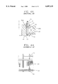
- FIGS. 2A and 2B a first example of a conventional structure in which the magnets are fixed to the magnet paddle 40 will be described.
- magnets 90 are fixed to an outer circumferential surface of the magnet paddle 40 by an adhesive at regular intervals.
- a plurality of slits 40a are formed in the magnet paddle 40 in order to reduce eddy current loss.
- a reference numeral 20a is a coil which is disposed in the outer lamination 20 and a power source is applied thereto, and a numeral 55 is a connecting member which connects the piston 50 to the magnet paddle 40.
- a plurality of grooves 41 for fixing the magnets are formed at the magnet paddle 40, and a plurality of magnets 90 are fixed to the corresponding grooves 41 by an adhesive.
- a base ring 42 and an end ring 43 are provided, and insertion grooves 42a and 43b are formed at facing surfaces of the base ring 42 and the end ring 43 and a plurality of magnets 90 are inserted into the corresponding grooves 42a and 43b.
- a reference numeral 45 is a nut for screwing onto each of the bolts 44 to fix the magnets 90, and reference numerals 20, 30 and 20a are the outer lamination, the inner lamination, and the coil, respectively.
- an object of the present invention is to provide a magnet fixed structure for a compressor motor that improves mass productivity of a compressor motor by preventing magnets from separating from a magnet paddle.
- Another object of the present invention is to provide a magnet fixed structure for a compressor motor that improves efficiency of a compressor motor by minimizing an empty space between an inner lamination and an outer lamination.
- a magnet fixed structure for a compressor motor wherein an inner lamination and an outer lamination are provided includes: a cylindrical magnet paddle operating between the inner lamination and the outer lamination, and having a plurality of magnet insertion holes or without the magnet insertion holes; a plurality of magnets which are respectively inserted into the magnet insertion holes of the magnet paddle or fixed to the magnet paddle; and a magnet fixing ring attached to both inner and outer surfaces of the magnet paddle, or attached to either an inner surface or an outer surface of the magnet paddle, or a molding member for forming a molding layer.
- FIG. 1 is a structure diagram of a conventional linear compressor
- FIG. 2A is a vertical cross-sectional view according to a first example of a magnet fixed structure of the conventional linear compressor
- FIG. 2B is a cross-sectional view taken along the line I-I' in FIG. 2A;
- FIG. 3A is a cross-sectional view according to a second example of the magnet fixed structure of the conventional linear compressor
- FIG. 3B is a front view of the magnet fixed structure in FIG. 3A;
- FIG. 4A is a cross-sectional view according to a third example of the magnet fixed structure of the conventional linear compressor
- FIG. 4B is a front view of the magnet fixed structure in FIG. 4A;
- FIG. 5A is a cross-sectional view of a magnet fixed structure for a compressor motor according to a first embodiment of the present invention
- FIG. 5B is a cross-sectional view taken along the line V-V' in FIG. 5A;
- FIG. 6 is a partially cut-away perspective view of the magnet fixed structure according to the first embodiment of the present invention.
- FIG. 7 is a cross-sectional view illustrating another type of the magnet fixed structure according to the first embodiment of the present invention.
- FIG. 8 is a perspective view of a magnet fixed structure for a compressor motor according to a second embodiment of the present invention.
- FIG. 9 is a vertical cross-sectional view of the magnet fixed structure according to the second embodiment of the present invention.
- FIG. 10 is a cross-sectional view taken along the line VI-VI' in FIG. 9;
- FIG. 11 is a schematic diagram illustrating a length of a gap between an inner lamination and an outer lamination of the compressor motor according to the present invention.
- FIG. 12 is a cross-sectional view of a magnet fixed structure for a compressor motor according to a third embodiment of the present invention.
- FIG. 13 is a cross-sectional view taken along the line VII-VII' in FIG. 12;
- FIG. 14 is a cross-sectional view of another type of the magnet fixed structure according to the third embodiment.
- FIG. 15 is a cross-sectional view taken along the line VIII-VIII' in FIG. 14.
- FIG. 5A illustrates a magnet fixed structure for a compressor motor according to a first embodiment of the present invention.
- a cylindrical magnet paddle 300 which is coupled with a piston (not shown) by a connecting member 310 and linearly straight reciprocates is disposed between an inner lamination 200 and an outer lamination 100 in which a coil 100a is disposed.
- a plurality of magnet insertion holes 300a are formed in the magnet paddle 300 at regular intervals.
- projected inner and outer circular arcs of each hole 300a have the identical length.
- Magnets 400 each of inner and outer circular arcs has the identical length are inserted into the corresponding magnet insertion holes 300a.
- magnet fixing rings 500a, 500b are put to an upper part to a lower part of the magnet paddle 300 into which the magnets 400 are inserted, for thereby being tightly attached to outer and inner circumferential surfaces of the magnet paddle 300.
- the one connected with the coil 100a is formed of a non-magnetic material and the other one is formed of a magnetic material.
- the fixing ring 500a attached to the outer side of the magnetic paddle 300 is formed of the non-magnetic body while the fixing ring 500b attached to the inner side thereof is the magnetic body.
- the fixing ring 500a attached to the outer side of the magnetic paddle 300 is formed of the magnetic body and the fixing ring 500b attached to the inner side thereof is formed of the non-magnetic body.
- FIG. 7 another type of the magnet fixed structure according to the first embodiment of the present invention will be described.
- magnet insertion holes 320a each projected inner circular arc is shorter than a corresponding projected outer circular arc are formed in a cylindrical magnet paddle 320 at a regular interval.
- magnets 410 having the same sectional shape as the magnet insertion hole 320a are inserted into the corresponding magnet insertion holes 320a.
- the magnet paddle 320 to which the magnets 410 are inserted is inserted into a magnet fixing ring 510 from an upper portion to a lower portion of the magnet paddle 320, for thus an outer circumferential surface of the magnet paddle 320 is tightly attached to an inner wall of the magnet fixing ring 510.
- the projected inner circular arc of the magnet insertion hole 320a can be longer than the corresponding projected outer circular arc thereof.
- the magnets 410 have the same sectional shape as the magnet insertion hole 320a.
- an outer circumferential surface of the magnet fixing ring 510 is tightly attached to an inner circumferential surface of the magnet paddle 320.
- FIGS. 8 through 10 A magnet fixed structure according to a second embodiment of the present invention will be described with reference to FIGS. 8 through 10.
- a disc-type second paddle 610 is fixed to a piston 630 by a fastening bolt 640 or a welding process, and a cylindrical first paddle 600 has a plurality of magnet insertion holes 600a each receiving a magnet 420.
- the first paddle 600 is fixed to the second paddle 610 by the welding.
- the first paddle 600 can be fixed to the second paddle 610 as a single body.
- a non-magnetic magnet fixing ring 620 having a plurality of slits 620a on a circumference thereof is tightly attached to outer circumferential surfaces of the magnets 420 which are inserted into the first paddle 600.
- a circular arc A of the magnet 420 is slightly longer than a circular arc B of the insertion hole 600a of the first paddle 600.
- An insertion portion 420a as thick as a thickness C of the first paddle 600 is formed at one side of the magnet 420 and inserted into the insertion hole 600a of the first paddle 600.
- the first paddle 600 into which the magnet 420 is inserted has a smooth inner circumferential surface.
- Reference numerals D and E are the thickness of the magnet 420 and the magnet fixing ring 620, respectively.
- each magnet 420 is inserted into the insertion hole 600a of the first paddle 600, and the first paddle 600 is inserted into the magnet fixing ring 620.
- outer surfaces of the magnets 420 are tightly attached to an inner wall of the magnet fixing ring 620.
- upper and lower end portions of the magnet fixing ring 620 are inwardly bent.
- the magnets 420 are more tightly fixed to the first paddle 600.
- the gap (c) between the inner and the outer laminations can be decreased by reducing the thickness of the fixing ring which fixes the magnets.
- t is a fixed thickness of the magnet required for the motor
- a is an extra length for mechanical processing ranged from 0.3 to 0.5 mm
- b is a thickness of the fixing member
- c is a width of the gap between the laminations.
- the slits 620a formed at the magnet fixing ring 620 reduce the eddy current loss occurred during the operation of the motor.
- a plurality of magnet insertion holes 700a each receiving a magnet 430 are formed along a circumference of a first magnet paddle 700.
- the first magnet paddle 700 is inserted into a non-magnetic magnet fixing ring 720.
- outer surfaces of the magnets 430 are attached to an inner wall of the magnet fixing ring 720.
- a varnish-type molding member 900 is applied to each surface of the first magnet paddle 700, the magnets 430 and the magnet fixing ring 720.
- the molding member 900 can be substituted for other materials, such an epoxy, which are not reactive to refrigerant and oil, thermostable and durable.
- Reference numerals 100, 200 and 710 are an outer lamination, an inner lamination and a second magnet paddle, respectively.
- the magnets 430 are inserted into the corresponding magnet insertion holes 700a of the first magnet paddle 700 linked with a piston (not shown), and the first paddle 700 inserted into the magnet fixing ring 720 is put in a molding solution for a predetermined time so that the molding solution soaks through each gap among the components 700, 430 and 720, or the solution spreads on each surface thereof.
- the magnets 430 are molded alone, the first paddle 700 and the magnets 430 are molded, the first paddle 700, the second paddle 710 and the magnets 430 are molded and the complete magnet fixed structure of the first paddle 700, the second paddle 710, the magnets 430 and the magnet fixing ring 720 is molded.
- a molding layer 900 is formed, for thus firmly fixing the components 700, 430 and 720. Since the thickness of the molding layer 900 is about 20 ⁇ m, the layer 900 does not seriously affect the length of the gap between the inner and outer laminations 100, 200.
- FIGS. 14 and 15 explain another type of the magnet fixed structure according to the third embodiment of the present invention.
- a cylindrical first paddle 800 to which a plurality of magnets 440 are fixed is put in a molding solution and taken out thereof, for thus a molding layer 900 is formed.
- the magnet fixed structure for the compressor motor according to the present invention prevents the magnets from coming off or being broken, for thus improving reliability and efficiency of the motor as well as mass productivity thereof.
Applications Claiming Priority (4)
| Application Number | Priority Date | Filing Date | Title |
|---|---|---|---|
| KR97-16049 | 1997-04-29 | ||
| KR1019970016049A KR100246387B1 (ko) | 1997-04-29 | 1997-04-29 | 리니어 모터의 마그네트 고정구조 |
| KR1019970021208A KR100212675B1 (ko) | 1997-05-28 | 1997-05-28 | 리니어 모터의 마그네트 고정구조 |
| KR97-21208 | 1997-05-28 |
Publications (1)
| Publication Number | Publication Date |
|---|---|
| US6097125A true US6097125A (en) | 2000-08-01 |
Family
ID=26632699
Family Applications (1)
| Application Number | Title | Priority Date | Filing Date |
|---|---|---|---|
| US09/067,714 Expired - Lifetime US6097125A (en) | 1997-04-29 | 1998-04-28 | Magnet fixed structure for compressor motor |
Country Status (5)
| Country | Link |
|---|---|
| US (1) | US6097125A (zh) |
| JP (1) | JP2992265B2 (zh) |
| CN (1) | CN1089961C (zh) |
| BR (1) | BR9801502B1 (zh) |
| DE (1) | DE19818950A1 (zh) |
Cited By (33)
| Publication number | Priority date | Publication date | Assignee | Title |
|---|---|---|---|---|
| US6252315B1 (en) * | 1997-12-10 | 2001-06-26 | Lg Electronics, Inc. | Magnet fixing structure for linear motor |
| WO2002078154A1 (en) | 2001-03-24 | 2002-10-03 | Lg Electronics Inc. | Mover assembly of reciprocating motor and fabrication method thereof |
| WO2002082624A2 (en) * | 2001-04-04 | 2002-10-17 | Empresa Brasileira De Compressores S.A. - Embraco | Permanent magnet support for a linear electric motor |
| US20020175793A1 (en) * | 2001-05-22 | 2002-11-28 | Soonhan Engineering Inc. | Magnet fixing method of a linear servo motor |
| WO2002095907A1 (en) * | 2001-05-22 | 2002-11-28 | Lg Electronics Inc. | Reciprocating motor |
| EP1305869A1 (en) * | 2001-05-24 | 2003-05-02 | Lg Electronics Inc. | Stator for reciprocating motor |
| US6653753B1 (en) * | 1999-04-13 | 2003-11-25 | Matsushita Electric Industrial Co., Ltd. | Linear motor |
| US20030230950A1 (en) * | 2002-06-17 | 2003-12-18 | Christian Reimann | Electric motor having a multipole rotor and a multipole stator |
| US20040071568A1 (en) * | 2001-12-10 | 2004-04-15 | Seong-Yeol Hyeon | Reliability-improving structure of reciprocating compressor |
| US20040090135A1 (en) * | 2002-11-08 | 2004-05-13 | Wavecrest Laboratories, Llc | Permanent magnet motor rotor having magnetic permeable material for enhanced flux distribution |
| US20050140217A1 (en) * | 2003-12-31 | 2005-06-30 | Lg Electronics Inc. | Apparatus for fixing stator of reciprocating compressor |
| US7032400B2 (en) | 2004-03-29 | 2006-04-25 | Hussmann Corporation | Refrigeration unit having a linear compressor |
| US20060290218A1 (en) * | 2005-06-23 | 2006-12-28 | Peopleflo Manufacturing Inc. | Inner magnet of a magnetic coupling |
| US20060288560A1 (en) * | 2005-06-24 | 2006-12-28 | Peopleflo Manufacturing Inc. | Assembly and method for pre-stressing a magnetic coupling canister |
| US20090079276A1 (en) * | 2005-03-30 | 2009-03-26 | Kazuhiko Ueda | Linear drive device |
| US20100301696A1 (en) * | 2007-10-09 | 2010-12-02 | Cardo Flow Solutions Ab | Rotor structure for a permanent magnet electrical machine |
| CN103790799A (zh) * | 2012-11-02 | 2014-05-14 | 海尔集团公司 | 线性压缩机 |
| US8922070B2 (en) | 2010-10-22 | 2014-12-30 | Linear Labs, Inc. | Magnetic motor |
| CN104251193A (zh) * | 2013-06-28 | 2014-12-31 | Lg电子株式会社 | 线性压缩机 |
| CN104251195A (zh) * | 2013-06-28 | 2014-12-31 | Lg电子株式会社 | 线性压缩机 |
| US20150004017A1 (en) * | 2013-06-28 | 2015-01-01 | Lg Electronics Inc. | Linear compressor |
| US20150333584A1 (en) * | 2014-05-15 | 2015-11-19 | Calnetix Technologies, Llc | High speed brushless dc electric machine |
| US9219962B2 (en) | 2012-09-03 | 2015-12-22 | Linear Labs, Inc. | Transducer and method of operation |
| CN105490411A (zh) * | 2014-09-19 | 2016-04-13 | 珠海格力节能环保制冷技术研究中心有限公司 | 一种动子结构、加工方法及直线电机 |
| US9325232B1 (en) | 2010-07-22 | 2016-04-26 | Linear Labs, Inc. | Method and apparatus for power generation |
| US9695811B2 (en) | 2013-06-28 | 2017-07-04 | Lg Electronics Inc. | Linear compressor |
| US9714648B2 (en) | 2013-06-28 | 2017-07-25 | Lg Electronics Inc. | Linear compressor |
| US9936300B2 (en) | 2012-09-03 | 2018-04-03 | Linear Labs, Inc | Transducer and method of operation |
| US20180198337A1 (en) * | 2017-01-10 | 2018-07-12 | Lg Electronics Inc. | Moving core-type reciprocating motor and reciprocating compressor having the same |
| US20180233975A1 (en) * | 2014-11-10 | 2018-08-16 | Mitsubishi Electric Corporation | Rotary electric machine |
| US10634127B2 (en) | 2013-06-28 | 2020-04-28 | Lg Electronics Inc. | Linear compressor |
| US20210367465A1 (en) * | 2019-02-08 | 2021-11-25 | Denso Corporation | Rotating electrical machine |
| US20230040807A1 (en) * | 2019-12-20 | 2023-02-09 | Xinjiang Goldwind Science & Technology Co., Ltd. | Rotor support, rotor, motor, and wind turbine |
Families Citing this family (9)
| Publication number | Priority date | Publication date | Assignee | Title |
|---|---|---|---|---|
| JP2002051521A (ja) * | 2000-07-28 | 2002-02-15 | Twinbird Corp | 電磁往復駆動機構 |
| KR100532035B1 (ko) * | 2001-03-23 | 2005-11-30 | 주식회사 엘지이아이 | 왕복동식 모터의 가동자 조립체 및 그 제조방법 |
| KR100394242B1 (ko) * | 2001-05-16 | 2003-08-09 | 주식회사 엘지이아이 | 왕복동식 모터의 마그네트 고정장치 |
| US6881042B2 (en) * | 2001-05-25 | 2005-04-19 | Lg Electronics Inc. | Reciprocating compressor having reduced vibration |
| KR100600765B1 (ko) * | 2004-11-02 | 2006-07-18 | 엘지전자 주식회사 | 리니어 압축기 |
| KR100682661B1 (ko) * | 2005-09-13 | 2007-02-15 | 엘지전자 주식회사 | 모터 및 상기 모터를 포함하는 세탁기 |
| KR101684841B1 (ko) * | 2014-03-05 | 2016-12-08 | 미쓰비시덴키 가부시키가이샤 | 영구 자석형 회전 전기 |
| CN105305677B (zh) * | 2014-07-28 | 2018-04-13 | 珠海格力节能环保制冷技术研究中心有限公司 | 动子结构、电机及动子结构的制作方法 |
| CN105406623B (zh) * | 2015-11-13 | 2018-08-07 | 珠海格力节能环保制冷技术研究中心有限公司 | 一种电机动子结构、动子结构制造方法及直线电机 |
Citations (10)
| Publication number | Priority date | Publication date | Assignee | Title |
|---|---|---|---|---|
| US4227105A (en) * | 1976-06-21 | 1980-10-07 | Shokichi Kumakura | Annular magnet assembly |
| US4549341A (en) * | 1983-07-19 | 1985-10-29 | The Garrett Corporation | Method for producing a permanent magnet rotor |
| US4591525A (en) * | 1983-08-03 | 1986-05-27 | Imperial Chemical Industries Plc | Transparent thermoplastic sheet |
| US4724348A (en) * | 1984-12-03 | 1988-02-09 | General Electric Company | Rotatable assembly for dynamoelectric machines having means for reducing release of magnet material particles therefrom |
| US4857786A (en) * | 1987-04-06 | 1989-08-15 | Hitachi, Ltd. | Structure of stepping motor and method of driving the stepping motor |
| US4954736A (en) * | 1988-04-25 | 1990-09-04 | Matsushita Electric Works, Ltd. | Permanent magnet rotor with magnets secured by synthetic resin |
| US5353491A (en) * | 1993-02-25 | 1994-10-11 | General Motors Corporation | Method of making frame and magnet assembly for a dynamoelectric machine |
| US5488260A (en) * | 1991-08-07 | 1996-01-30 | Johnson Electric S.A. | Encapsulated magnets in a permanent magnet rotor |
| US5744887A (en) * | 1995-04-14 | 1998-04-28 | Matsushita Electric Industrial Co., Ltd. | Permanent magnet rotor and manufacturing method thereof |
| US5751075A (en) * | 1995-11-14 | 1998-05-12 | L.G. Electronics Inc. | Magnet assembly for linear motor |
-
1998
- 1998-04-28 US US09/067,714 patent/US6097125A/en not_active Expired - Lifetime
- 1998-04-28 BR BRPI9801502-8A patent/BR9801502B1/pt not_active IP Right Cessation
- 1998-04-28 JP JP10119336A patent/JP2992265B2/ja not_active Expired - Fee Related
- 1998-04-28 DE DE19818950A patent/DE19818950A1/de not_active Ceased
- 1998-04-29 CN CN98101816.5A patent/CN1089961C/zh not_active Expired - Fee Related
Patent Citations (10)
| Publication number | Priority date | Publication date | Assignee | Title |
|---|---|---|---|---|
| US4227105A (en) * | 1976-06-21 | 1980-10-07 | Shokichi Kumakura | Annular magnet assembly |
| US4549341A (en) * | 1983-07-19 | 1985-10-29 | The Garrett Corporation | Method for producing a permanent magnet rotor |
| US4591525A (en) * | 1983-08-03 | 1986-05-27 | Imperial Chemical Industries Plc | Transparent thermoplastic sheet |
| US4724348A (en) * | 1984-12-03 | 1988-02-09 | General Electric Company | Rotatable assembly for dynamoelectric machines having means for reducing release of magnet material particles therefrom |
| US4857786A (en) * | 1987-04-06 | 1989-08-15 | Hitachi, Ltd. | Structure of stepping motor and method of driving the stepping motor |
| US4954736A (en) * | 1988-04-25 | 1990-09-04 | Matsushita Electric Works, Ltd. | Permanent magnet rotor with magnets secured by synthetic resin |
| US5488260A (en) * | 1991-08-07 | 1996-01-30 | Johnson Electric S.A. | Encapsulated magnets in a permanent magnet rotor |
| US5353491A (en) * | 1993-02-25 | 1994-10-11 | General Motors Corporation | Method of making frame and magnet assembly for a dynamoelectric machine |
| US5744887A (en) * | 1995-04-14 | 1998-04-28 | Matsushita Electric Industrial Co., Ltd. | Permanent magnet rotor and manufacturing method thereof |
| US5751075A (en) * | 1995-11-14 | 1998-05-12 | L.G. Electronics Inc. | Magnet assembly for linear motor |
Cited By (76)
| Publication number | Priority date | Publication date | Assignee | Title |
|---|---|---|---|---|
| US6252315B1 (en) * | 1997-12-10 | 2001-06-26 | Lg Electronics, Inc. | Magnet fixing structure for linear motor |
| US6653753B1 (en) * | 1999-04-13 | 2003-11-25 | Matsushita Electric Industrial Co., Ltd. | Linear motor |
| US7071584B2 (en) | 1999-04-13 | 2006-07-04 | Matsushita Electric Industrial Co., Ltd. | Linear motor |
| US20040207272A1 (en) * | 1999-04-13 | 2004-10-21 | Matsushita Electric Industrial Co., Ltd. | Linear motor |
| EP1380093A4 (en) * | 2001-03-24 | 2006-08-09 | Lg Electronics Inc | MOTOR DEVICE ASSEMBLY OF A PENDULUM MOTOR AND MANUFACTURING METHOD THEREFOR |
| US8049374B2 (en) | 2001-03-24 | 2011-11-01 | Lg Electronics Inc. | Mover assembly of reciprocating motor |
| US6920682B2 (en) * | 2001-03-24 | 2005-07-26 | Lg Electronics Inc. | Mover assembly of reciprocating motor |
| US20030110615A1 (en) * | 2001-03-24 | 2003-06-19 | Bon-Cheol Ku | Mover assembly of reciprocating motor and fabrication method thereof |
| EP1380093A1 (en) * | 2001-03-24 | 2004-01-14 | Lg Electronics Inc. | Mover assembly of reciprocating motor and fabrication method thereof |
| WO2002078154A1 (en) | 2001-03-24 | 2002-10-03 | Lg Electronics Inc. | Mover assembly of reciprocating motor and fabrication method thereof |
| US20050235481A1 (en) * | 2001-03-24 | 2005-10-27 | Lg Electronics Inc. | Mover assembly of reciprocating motor |
| WO2002082624A3 (en) * | 2001-04-04 | 2003-02-13 | Brasil Compressores Sa | Permanent magnet support for a linear electric motor |
| WO2002082624A2 (en) * | 2001-04-04 | 2002-10-17 | Empresa Brasileira De Compressores S.A. - Embraco | Permanent magnet support for a linear electric motor |
| US7015613B2 (en) | 2001-04-04 | 2006-03-21 | Empresa Brasileira De Compressores S.A. -Embraco | Linear electric motor |
| US20040145247A1 (en) * | 2001-04-04 | 2004-07-29 | Dietmar Erich Bernhard Lilie | Linear electric motor |
| CN1310408C (zh) * | 2001-04-04 | 2007-04-11 | 巴西船用压缩机有限公司 | 线性电马达 |
| US6848164B2 (en) * | 2001-05-22 | 2005-02-01 | Soonhan Engineering, Inc. | Magnet fixing method of a linear servo motor |
| CN100454730C (zh) * | 2001-05-22 | 2009-01-21 | Lg电子株式会社 | 往复式电动机 |
| US20020175793A1 (en) * | 2001-05-22 | 2002-11-28 | Soonhan Engineering Inc. | Magnet fixing method of a linear servo motor |
| US6900558B1 (en) * | 2001-05-22 | 2005-05-31 | Lg Electronics Inc. | Reciprocating motor |
| WO2002095907A1 (en) * | 2001-05-22 | 2002-11-28 | Lg Electronics Inc. | Reciprocating motor |
| EP1305869A1 (en) * | 2001-05-24 | 2003-05-02 | Lg Electronics Inc. | Stator for reciprocating motor |
| EP1305869A4 (en) * | 2001-05-24 | 2006-04-26 | Lg Electronics Inc | STATOR FOR ALTERNATIVE MOTOR |
| US20040071568A1 (en) * | 2001-12-10 | 2004-04-15 | Seong-Yeol Hyeon | Reliability-improving structure of reciprocating compressor |
| US7284967B2 (en) * | 2001-12-10 | 2007-10-23 | Lg Electronics, Inc. | Reliability-improving structure of reciprocating compressor |
| US6960856B2 (en) * | 2002-06-17 | 2005-11-01 | Siemens Aktiengesellschaft | Electric motor having a multipole rotor and a multipole stator |
| US20030230950A1 (en) * | 2002-06-17 | 2003-12-18 | Christian Reimann | Electric motor having a multipole rotor and a multipole stator |
| US20040090135A1 (en) * | 2002-11-08 | 2004-05-13 | Wavecrest Laboratories, Llc | Permanent magnet motor rotor having magnetic permeable material for enhanced flux distribution |
| US6844645B2 (en) * | 2002-11-08 | 2005-01-18 | Wavecrest Laboratories, Llc | Permanent magnet motor rotor having magnetic permeable material for enhanced flux distribution |
| US7061145B2 (en) * | 2003-12-31 | 2006-06-13 | Lg Electronics Inc. | Apparatus for fixing stator of reciprocating compressor |
| US20050140217A1 (en) * | 2003-12-31 | 2005-06-30 | Lg Electronics Inc. | Apparatus for fixing stator of reciprocating compressor |
| US7032400B2 (en) | 2004-03-29 | 2006-04-25 | Hussmann Corporation | Refrigeration unit having a linear compressor |
| US7540164B2 (en) | 2004-03-29 | 2009-06-02 | Hussmann Corporation | Refrigeration unit having a linear compressor |
| US7649285B2 (en) * | 2005-03-30 | 2010-01-19 | Sharp Kabushiki Kaisha | Linear drive device |
| US20090079276A1 (en) * | 2005-03-30 | 2009-03-26 | Kazuhiko Ueda | Linear drive device |
| US20060290218A1 (en) * | 2005-06-23 | 2006-12-28 | Peopleflo Manufacturing Inc. | Inner magnet of a magnetic coupling |
| US7183683B2 (en) | 2005-06-23 | 2007-02-27 | Peopleflo Manufacturing Inc. | Inner magnet of a magnetic coupling |
| US20060288560A1 (en) * | 2005-06-24 | 2006-12-28 | Peopleflo Manufacturing Inc. | Assembly and method for pre-stressing a magnetic coupling canister |
| US7549205B2 (en) | 2005-06-24 | 2009-06-23 | Peopleflo Manufacturing Inc. | Assembly and method for pre-stressing a magnetic coupling canister |
| US20100301696A1 (en) * | 2007-10-09 | 2010-12-02 | Cardo Flow Solutions Ab | Rotor structure for a permanent magnet electrical machine |
| US8304948B2 (en) * | 2007-10-09 | 2012-11-06 | Sulzer Pump Solutions Ab | Rotor structure for a permanent magnet electrical machine |
| US9325232B1 (en) | 2010-07-22 | 2016-04-26 | Linear Labs, Inc. | Method and apparatus for power generation |
| US11218067B2 (en) | 2010-07-22 | 2022-01-04 | Linear Labs, Inc. | Method and apparatus for power generation |
| US10587178B2 (en) | 2010-07-22 | 2020-03-10 | Linear Labs, Inc. | Method and apparatus for power generation |
| US8922070B2 (en) | 2010-10-22 | 2014-12-30 | Linear Labs, Inc. | Magnetic motor |
| US9325219B2 (en) | 2010-10-22 | 2016-04-26 | Linear Labs, Inc. | Magnetic motor and method of use |
| US20220123625A1 (en) * | 2010-10-22 | 2022-04-21 | Linear Labs, Inc. | Magnetic motor and method of use |
| US11165307B2 (en) * | 2010-10-22 | 2021-11-02 | Linear Labs, Inc. | Magnetic motor and method of use |
| US10291096B2 (en) | 2010-10-22 | 2019-05-14 | Linear Labs, LLC | Magnetic motor and method of use |
| US20230216370A1 (en) * | 2010-10-22 | 2023-07-06 | Linear Labs, Inc. | Magnetic motor and method of use |
| US10575100B2 (en) | 2012-09-03 | 2020-02-25 | Linear Labs, LLC | Transducer and method of operation |
| US9219962B2 (en) | 2012-09-03 | 2015-12-22 | Linear Labs, Inc. | Transducer and method of operation |
| US9936300B2 (en) | 2012-09-03 | 2018-04-03 | Linear Labs, Inc | Transducer and method of operation |
| CN103790799A (zh) * | 2012-11-02 | 2014-05-14 | 海尔集团公司 | 线性压缩机 |
| CN104251195A (zh) * | 2013-06-28 | 2014-12-31 | Lg电子株式会社 | 线性压缩机 |
| CN104251193A (zh) * | 2013-06-28 | 2014-12-31 | Lg电子株式会社 | 线性压缩机 |
| US9695811B2 (en) | 2013-06-28 | 2017-07-04 | Lg Electronics Inc. | Linear compressor |
| US9695810B2 (en) * | 2013-06-28 | 2017-07-04 | Lg Electronics Inc. | Linear compressor |
| US9714648B2 (en) | 2013-06-28 | 2017-07-25 | Lg Electronics Inc. | Linear compressor |
| US9726164B2 (en) * | 2013-06-28 | 2017-08-08 | Lg Electronics Inc. | Linear compressor |
| US9677553B2 (en) * | 2013-06-28 | 2017-06-13 | Lg Electronics Inc. | Linear compressor |
| US20150004026A1 (en) * | 2013-06-28 | 2015-01-01 | Lg Electronics Inc. | Linear compressor |
| US20150004017A1 (en) * | 2013-06-28 | 2015-01-01 | Lg Electronics Inc. | Linear compressor |
| US10634127B2 (en) | 2013-06-28 | 2020-04-28 | Lg Electronics Inc. | Linear compressor |
| US20150004028A1 (en) * | 2013-06-28 | 2015-01-01 | Lg Electronics Inc. | Linear compressor |
| EP2818712A3 (en) * | 2013-06-28 | 2015-10-21 | LG Electronics, Inc. | Linear compressor |
| EP2818711A3 (en) * | 2013-06-28 | 2015-10-21 | LG Electronics, Inc. | Linear compressor |
| US20150333584A1 (en) * | 2014-05-15 | 2015-11-19 | Calnetix Technologies, Llc | High speed brushless dc electric machine |
| CN105490411A (zh) * | 2014-09-19 | 2016-04-13 | 珠海格力节能环保制冷技术研究中心有限公司 | 一种动子结构、加工方法及直线电机 |
| US10320252B2 (en) * | 2014-11-10 | 2019-06-11 | Mitsubishi Electric Corporation | Rotary electric machine |
| US20180233975A1 (en) * | 2014-11-10 | 2018-08-16 | Mitsubishi Electric Corporation | Rotary electric machine |
| US10811920B2 (en) * | 2017-01-10 | 2020-10-20 | Lg Electronics Inc. | Moving core-type reciprocating motor and reciprocating compressor having the same |
| US20180198337A1 (en) * | 2017-01-10 | 2018-07-12 | Lg Electronics Inc. | Moving core-type reciprocating motor and reciprocating compressor having the same |
| US20210367465A1 (en) * | 2019-02-08 | 2021-11-25 | Denso Corporation | Rotating electrical machine |
| US20230040807A1 (en) * | 2019-12-20 | 2023-02-09 | Xinjiang Goldwind Science & Technology Co., Ltd. | Rotor support, rotor, motor, and wind turbine |
| US11764656B2 (en) * | 2019-12-20 | 2023-09-19 | Xinjiang Goldwind Science & Technology Co., Ltd. | Rotor support, rotor, motor, and wind turbine |
Also Published As
| Publication number | Publication date |
|---|---|
| DE19818950A1 (de) | 1998-11-05 |
| BR9801502A (pt) | 1999-10-19 |
| BR9801502B1 (pt) | 2011-06-28 |
| JP2992265B2 (ja) | 1999-12-20 |
| JPH10323003A (ja) | 1998-12-04 |
| CN1198034A (zh) | 1998-11-04 |
| CN1089961C (zh) | 2002-08-28 |
Similar Documents
| Publication | Publication Date | Title |
|---|---|---|
| US6097125A (en) | Magnet fixed structure for compressor motor | |
| US6917127B2 (en) | Outer stator for linear compressor motors | |
| CN1071001C (zh) | 振动压缩机 | |
| US5744887A (en) | Permanent magnet rotor and manufacturing method thereof | |
| US20040251749A1 (en) | Reciprocating motor | |
| US4210831A (en) | Involute lamination armature for a linear reciprocating motor | |
| KR0176875B1 (ko) | 리니어 압축기의 피스톤 하중 지지장치 | |
| JP2000102201A (ja) | 永久磁石ロータ及びその製造方法 | |
| US6980072B2 (en) | Linear actuator, and pump and compressor devices using the actuator | |
| JPH027264B2 (zh) | ||
| KR100246428B1 (ko) | 리니어 모터의 내측고정자 고정구조 | |
| KR19990048726A (ko) | 리니어 모터의 마그네트 고정구조 | |
| US7322199B2 (en) | Stirling cooler | |
| KR100212675B1 (ko) | 리니어 모터의 마그네트 고정구조 | |
| KR100246387B1 (ko) | 리니어 모터의 마그네트 고정구조 | |
| JP2001078376A (ja) | 回転電機用磁石回転子 | |
| JPS6185046A (ja) | 磁石発電機の回転子の製造方法 | |
| JP2001178029A (ja) | フライホイールマグネト用ステータ | |
| JP4015131B2 (ja) | リニア圧縮機 | |
| KR20040051676A (ko) | 압축기용 회전자 | |
| KR200162308Y1 (ko) | 선형압축기의 모터구조 | |
| KR100214638B1 (ko) | 리니어 압축기의 마그네트 고정장치 | |
| JPS6315826B2 (zh) | ||
| JPH08149771A (ja) | 磁石発電機の固定子およびその製造方法 | |
| KR0134103Y1 (ko) | 선형압축기 고정자 |
Legal Events
| Date | Code | Title | Description |
|---|---|---|---|
| AS | Assignment |
Owner name: LG ELECTRONICS INC., KOREA, REPUBLIC OF Free format text: ASSIGNMENT OF ASSIGNORS INTEREST;ASSIGNORS:PARK, JUNG SIK;LEE, HYEONG KOOK;HEO, JONG TAE;AND OTHERS;REEL/FRAME:009166/0969 Effective date: 19980415 |
|
| STCF | Information on status: patent grant |
Free format text: PATENTED CASE |
|
| FEPP | Fee payment procedure |
Free format text: PAYOR NUMBER ASSIGNED (ORIGINAL EVENT CODE: ASPN); ENTITY STATUS OF PATENT OWNER: LARGE ENTITY |
|
| FPAY | Fee payment |
Year of fee payment: 4 |
|
| FPAY | Fee payment |
Year of fee payment: 8 |
|
| FEPP | Fee payment procedure |
Free format text: PAYOR NUMBER ASSIGNED (ORIGINAL EVENT CODE: ASPN); ENTITY STATUS OF PATENT OWNER: LARGE ENTITY Free format text: PAYER NUMBER DE-ASSIGNED (ORIGINAL EVENT CODE: RMPN); ENTITY STATUS OF PATENT OWNER: LARGE ENTITY |
|
| FPAY | Fee payment |
Year of fee payment: 12 |