US6070883A - Sealing unit for a fuel pressure sensor - Google Patents
Sealing unit for a fuel pressure sensor Download PDFInfo
- Publication number
- US6070883A US6070883A US08/860,375 US86037597A US6070883A US 6070883 A US6070883 A US 6070883A US 86037597 A US86037597 A US 86037597A US 6070883 A US6070883 A US 6070883A
- Authority
- US
- United States
- Prior art keywords
- sealing
- sealing washer
- pin
- fuel pressure
- pressure sensor
- Prior art date
- Legal status (The legal status is an assumption and is not a legal conclusion. Google has not performed a legal analysis and makes no representation as to the accuracy of the status listed.)
- Expired - Lifetime
Links
Images

Classifications
-
- G—PHYSICS
- G01—MEASURING; TESTING
- G01L—MEASURING FORCE, STRESS, TORQUE, WORK, MECHANICAL POWER, MECHANICAL EFFICIENCY, OR FLUID PRESSURE
- G01L23/00—Devices or apparatus for measuring or indicating or recording rapid changes, such as oscillations, in the pressure of steam, gas, or liquid; Indicators for determining work or energy of steam, internal-combustion, or other fluid-pressure engines from the condition of the working fluid
- G01L23/26—Details or accessories
-
- Y—GENERAL TAGGING OF NEW TECHNOLOGICAL DEVELOPMENTS; GENERAL TAGGING OF CROSS-SECTIONAL TECHNOLOGIES SPANNING OVER SEVERAL SECTIONS OF THE IPC; TECHNICAL SUBJECTS COVERED BY FORMER USPC CROSS-REFERENCE ART COLLECTIONS [XRACs] AND DIGESTS
- Y10—TECHNICAL SUBJECTS COVERED BY FORMER USPC
- Y10S—TECHNICAL SUBJECTS COVERED BY FORMER USPC CROSS-REFERENCE ART COLLECTIONS [XRACs] AND DIGESTS
- Y10S285/00—Pipe joints or couplings
- Y10S285/917—Metallic seals
Definitions
- the invention is based on a sealing unit for a fuel pressure sensor.
- sealing units of this kind constitute a fuel pressure sensor in combination with a sealing washer. Both parts are separate from each other.
- the sealing washer is first inserted into the bore.
- the threaded bores are often let into the fuel carrying component from the side or even from underneath so that the insertion of the sealing washer is difficult simply because of gravity.
- the threaded bores are partially or completely impossible to see into because they are blocked from view by components disposed in front of them, so that the position of the sealing washer before the insertion of the fuel pressure sensor cannot be optically controlled without some means of assistance. Therefore an off-center or tilted seating of the sealing washer cannot be detected. Consequently, leaks or damage to the threaded bore or the fuel pressure sensor, which arise when the fuel pressure sensor is tightened, are not detected.
- the sealing washer is usually still seated at the bottom of the threaded bore after the fuel pressure sensor has been unscrewed.
- the washer sticks there, among other things, by means of adhesion with fuel residues or by means of being jammed in the thread runout.
- the subsequent removal is only possible through the expenditure of a considerable amount of time. At the same time, it includes the danger of mechanically damaging the bottom of the threaded bore, which serves as the sealing face, which can lead to leaks when the fuel carrying component is reused.
- a sealing unit In order to avoid the disadvantages associated with the prior art described, a sealing unit must be produced, which assures a reliable sealing function and a simple installation and disassembly of the sealing washer.
- a pin is formed onto the threaded bolt-shaped end of the sensor housing, which pin centers the sealing washer, fixing it in a positive and/or frictional, non-positive manner, and rises above an end face that serves as a bearing surface for the sealing washer.
- the pin which ends in an end face, has a length that is shorter than the thickness of the sealing washer.
- the sealing washer Before the fuel pressure sensor is screwed into the fuel carrying component, the sealing washer is placed on the pin.
- the sealing washer is held on the pin, for example with the aid of a lateral press fit.
- the sealing washer can also be glued in the region of the pin.
- the sealing washer is axially compressed by means of the tightening of the fuel pressure sensor, by means of which a frictional, non-positive connection between the pin and the bore of the sealing washer is produced or at least reinforced.
- the sealing washer is attached to the fuel pressure sensor so that during storage, transport, installation, and disassembly of the fuel pressure sensor, the sealing washer remains fixed to the fuel pressure sensor in captive fashion. Consequently, the sealing washer cannot be forgotten during installation, nor can it be inserted into the threaded bore of the component in an off-center manner. As a result, most of the causes for a leak in the sealing joint between the bottom of the threaded bore and the sealing washer are eliminated. Likewise, the fixing of the sealing washer on the pin virtually rules out the possibly of a leak in the sealing joint between the sealing washer and the pin or the flat bearing surface on the threaded bolt end. Furthermore, the flat bearing surface is covered and consequently protected by the sealing washer during storage, transport, and installation.
- the pin can alternatively also be embodied in the form of a truncated cone.
- the cone diameter in the region of the sensor end sealing face is smaller than at the free end of the pin.
- the sealing washer is seated on a pin of this kind, for example via a snug fit or a glued connection.
- the sealing washer can also be fixed by means of partial deformations in the region of the pin edge. The deformation of the sealing washer is produced at one or more points in the region of the pin edge, for example with the aid of tools similar to center punches or drift punches. At these points, the material of the sealing washer is compressed and displaced in sections so that in these locations, it touches or engages behind the truncated cone-shaped outer contour of the pin.
- the complete rear engagement with which the sealing washer material at least encompasses the outer contour in a virtual ring, is produced when the fuel pressure sensor is tightened in the threaded bore.
- the sealing material is plastically deformed and rests against the outer contour of the pin in a sealing, positive, and frictional, non-positive manner.
- the sealing washer When the fuel pressure sensor is disassembled, the sealing washer is separated from the fuel carrying component while being unscrewed, because of the tensile and shear motion in the sealing joint between the sealing washer and the bottom of the threaded bore, and the sealing washer is removed from the threaded bore along with the fuel pressure sensor.
- FIG. 1 shows a screwable end of the fuel pressure sensor with a sealing washer and an opposing piece
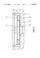
- FIG. 2 shows the screw installed fuel pressure sensor with a truncated cone-shaped pin and a deformed sealing washer.
- FIG. 1 shows the threaded bolt-shaped end (21) of a fuel pressure sensor (20), a sealing washer (10) and a threaded bore (2) for receiving the fuel pressure sensor (20) in a pressure fluid carrying component (1).
- the components here are represented in a disassembled state.
- the outer contour of the threaded bolt-shaped end (21) includes a threaded section (22), a bearing section (23) adjoining this, and a centering pin (26) formed onto this bearing section.
- the bearing section (23) has a cylindrical outer contour whose diameter is smaller than the core diameter of the thread (22).
- the cylindrical outer contour transitions into an annular end face (24) via a chamfer. This end face (24) is used as the sensor end sealing face.
- the centering pin (26) likewise has a cylindrical outer contour, whose diameter is slightly larger than the inner diameter of the sealing washer (10).
- the centering pin (26) ends in an end face (28). The length of the centering pin (26) is shorter than the thickness of the sealing washer (10).
- the threaded bolt-shaped end (21) of the fuel pressure sensor (20) has a central bore (29), which feeds into the end face (28).
- the transition region is chamfered.
- a threaded bore (2) is disposed in the component (1) that carries the fuel pressure sensor (20) and the sensor is seated in this bore when installed.
- the bottom of the threaded bore (2) is a smooth face that functions as a component end sealing face.
- the diameter there is matched in proportion to the outer diameter of the sealing washer (10) so that the outer diameter of the sealing washer (10), which increases as a result of assembly, is reliably smaller than the inner diameter of the threaded bore (2) or the bottom of the threaded bore.
- a pressure fluid opening (3) is disposed centrally in the bottom of the threaded bore (2).
- FIG. 2 shows a fuel pressure sensor (20') in the installed state.
- the centering pin (26') of the fuel pressure sensor (20') has an outer contour in the shape of a truncated cone whose diameter decreases from the free end or from the end face (28) toward the threaded section (21).
- this contour permits a positive connection between the fuel pressure sensor (20') and the sealing washer (10) because of the deformation or the flattening and mushrooming over of the sealing washer (10).
- the sealing washer (10) is attached to the centering pin (26') in captive fashion with the aid of a close, snug fit.
- the un-deformed sealing washer (10) can also be glued to the annular end face (24).
- the fuel pressure sensor (20') When the fuel pressure sensor (20') is installed, it is inserted into the threaded bore together with the sealing washer (10) attached to it and is screwed in. After the sealing washer (10) comes into contact with the component end sealing face, the sealing washer (10) is deformed by being pressed flat when the screw connection is tightened as provided. By means of the material displacement among other things, the inner diameter of the sealing washer (10) is reduced and the outer diameter is enlarged. By means of the deformation of the inner diameter, the sealing washer (10) engages behind the centering pin (26'), see FIG. 2. The height of the sealing washer (10) after the deformation is still greater than the height of the centering pin (26').
- the used, deformed sealing washer (10) adheres to the threaded bolt-shaped end (21) of the fuel pressure sensor (20').
- the sealing washer (10) can be separated from the fuel pressure sensor (20') with the aid of cutting pliers, without the danger of damaging the sensor in order, if need be, to outfit the fuel pressure sensor (20') for reuse with a new sealing washer (10).
Applications Claiming Priority (3)
| Application Number | Priority Date | Filing Date | Title |
|---|---|---|---|
| DE19547890A DE19547890A1 (de) | 1995-12-21 | 1995-12-21 | Dichtungseinheit für einen Kraftstoffdrucksensor |
| DE19547890 | 1995-12-21 | ||
| PCT/DE1996/001420 WO1997023771A1 (de) | 1995-12-21 | 1996-07-31 | Dichtungseinheit für einen kraftstoffdrucksensor |
Publications (1)
| Publication Number | Publication Date |
|---|---|
| US6070883A true US6070883A (en) | 2000-06-06 |
Family
ID=7780850
Family Applications (1)
| Application Number | Title | Priority Date | Filing Date |
|---|---|---|---|
| US08/860,375 Expired - Lifetime US6070883A (en) | 1995-12-21 | 1996-07-31 | Sealing unit for a fuel pressure sensor |
Country Status (6)
| Country | Link |
|---|---|
| US (1) | US6070883A (de) |
| EP (1) | EP0811151B1 (de) |
| JP (1) | JPH11501400A (de) |
| KR (1) | KR100235366B1 (de) |
| DE (2) | DE19547890A1 (de) |
| WO (1) | WO1997023771A1 (de) |
Cited By (12)
| Publication number | Priority date | Publication date | Assignee | Title |
|---|---|---|---|---|
| US20030102387A1 (en) * | 2001-10-12 | 2003-06-05 | Mario Ricco | Device for fluid-tight connection of a fitting to an internal combustion engine fuel injector |
| US20060090567A1 (en) * | 2004-10-29 | 2006-05-04 | Caterpillar Inc. | Fluid sensor having a low pressure drain |
| US20080191476A1 (en) * | 2007-02-14 | 2008-08-14 | Nagano Keiki Co., Ltd. | Joint for measuring device and method of manufacturing the joint |
| US20120256379A1 (en) * | 2011-04-11 | 2012-10-11 | David Edward Rubin | Apparatus and methods for temporarily sealing a pipe |
| GB2553156A (en) * | 2015-11-13 | 2018-02-28 | Sensata Technologies Inc | Pressure sensor |
| US20180347617A1 (en) * | 2017-05-30 | 2018-12-06 | Sensata Technologies, Inc. | Washer fixation method and system |
| US10323998B2 (en) | 2017-06-30 | 2019-06-18 | Sensata Technologies, Inc. | Fluid pressure sensor |
| US10488289B2 (en) | 2016-04-11 | 2019-11-26 | Sensata Technologies, Inc. | Pressure sensors with plugs for cold weather protection and methods for manufacturing the plugs |
| US10545064B2 (en) | 2017-05-04 | 2020-01-28 | Sensata Technologies, Inc. | Integrated pressure and temperature sensor |
| US10557770B2 (en) | 2017-09-14 | 2020-02-11 | Sensata Technologies, Inc. | Pressure sensor with improved strain gauge |
| US10724907B2 (en) | 2017-07-12 | 2020-07-28 | Sensata Technologies, Inc. | Pressure sensor element with glass barrier material configured for increased capacitive response |
| US10871413B2 (en) | 2016-04-20 | 2020-12-22 | Sensata Technologies, Inc. | Method of manufacturing a pressure sensor |
Families Citing this family (4)
| Publication number | Priority date | Publication date | Assignee | Title |
|---|---|---|---|---|
| US5855397A (en) * | 1997-04-02 | 1999-01-05 | Cummins Engine Company, Inc. | High-pressure sealable connector for a pressure sensor |
| DE102008001865A1 (de) | 2008-05-19 | 2009-11-26 | Endress + Hauser Gmbh + Co. Kg | Messgerät |
| DE102015216150A1 (de) * | 2015-08-25 | 2017-03-02 | Volkswagen Aktiengesellschaft | Dichtungsanordnung für eine Kraftstoffzuleitung |
| DE102019209033A1 (de) * | 2019-06-21 | 2020-12-24 | Metallux Ag | Drucksensoreinrichtung |
Citations (12)
| Publication number | Priority date | Publication date | Assignee | Title |
|---|---|---|---|---|
| GB190624881A (en) * | 1906-11-06 | 1907-03-07 | Samuel Wilson Amphlet | Improvements in Pressure Gauge or Pressure Testing Attachments for use in connection with Pneumatic Tyres and other Inflatable Articles |
| US1424094A (en) * | 1920-05-17 | 1922-07-25 | Robert W Gunn | Valve seat |
| GB589310A (en) * | 1945-01-04 | 1947-06-17 | Charles Robert Archibald Grant | Improvements in or relating to pressure or vacuum gauges |
| GB1380410A (en) * | 1971-12-02 | 1975-01-15 | Whessoe Ltd | Making seal assemblies |
| US4227420A (en) * | 1979-06-11 | 1980-10-14 | Baxter Travenol Laboratories, Inc. | Pressure coupling mechanism in a pressure monitoring assembly |
| US4543832A (en) * | 1983-09-30 | 1985-10-01 | Transducers, Inc. | Overload protected pressure transducer |
| US4650227A (en) * | 1982-08-23 | 1987-03-17 | Cajon Company | Fluid coupling |
| US5011196A (en) * | 1989-04-12 | 1991-04-30 | Andre Sabatier | Union for fluid conduits, in particular for high purity gas |
| EP0567924A1 (de) * | 1992-04-27 | 1993-11-03 | Tadahiro Ohmi | Rohrverbindung |
| WO1993022646A1 (de) * | 1992-04-27 | 1993-11-11 | Endress U. Hauser Gmbh U. Co. | Vorrichtung zum messen von druck und differenzdruck |
| US5313839A (en) * | 1992-08-31 | 1994-05-24 | Ridenour Ralph Gaylord | Transducer assembly and method |
| US5992595A (en) * | 1997-09-26 | 1999-11-30 | Ntn Corporation | Hub clutch assembly |
-
1995
- 1995-12-21 DE DE19547890A patent/DE19547890A1/de not_active Withdrawn
-
1996
- 1996-07-31 US US08/860,375 patent/US6070883A/en not_active Expired - Lifetime
- 1996-07-31 WO PCT/DE1996/001420 patent/WO1997023771A1/de active IP Right Grant
- 1996-07-31 JP JP9523194A patent/JPH11501400A/ja active Pending
- 1996-07-31 EP EP96924785A patent/EP0811151B1/de not_active Expired - Lifetime
- 1996-07-31 DE DE59608265T patent/DE59608265D1/de not_active Expired - Lifetime
- 1996-07-31 KR KR1019970705737A patent/KR100235366B1/ko not_active IP Right Cessation
Patent Citations (13)
| Publication number | Priority date | Publication date | Assignee | Title |
|---|---|---|---|---|
| GB190624881A (en) * | 1906-11-06 | 1907-03-07 | Samuel Wilson Amphlet | Improvements in Pressure Gauge or Pressure Testing Attachments for use in connection with Pneumatic Tyres and other Inflatable Articles |
| US1424094A (en) * | 1920-05-17 | 1922-07-25 | Robert W Gunn | Valve seat |
| GB589310A (en) * | 1945-01-04 | 1947-06-17 | Charles Robert Archibald Grant | Improvements in or relating to pressure or vacuum gauges |
| GB1380410A (en) * | 1971-12-02 | 1975-01-15 | Whessoe Ltd | Making seal assemblies |
| US4227420A (en) * | 1979-06-11 | 1980-10-14 | Baxter Travenol Laboratories, Inc. | Pressure coupling mechanism in a pressure monitoring assembly |
| US4650227A (en) * | 1982-08-23 | 1987-03-17 | Cajon Company | Fluid coupling |
| US4650227B1 (en) * | 1982-08-23 | 2000-11-28 | Cajon Co | Fluid coupling |
| US4543832A (en) * | 1983-09-30 | 1985-10-01 | Transducers, Inc. | Overload protected pressure transducer |
| US5011196A (en) * | 1989-04-12 | 1991-04-30 | Andre Sabatier | Union for fluid conduits, in particular for high purity gas |
| EP0567924A1 (de) * | 1992-04-27 | 1993-11-03 | Tadahiro Ohmi | Rohrverbindung |
| WO1993022646A1 (de) * | 1992-04-27 | 1993-11-11 | Endress U. Hauser Gmbh U. Co. | Vorrichtung zum messen von druck und differenzdruck |
| US5313839A (en) * | 1992-08-31 | 1994-05-24 | Ridenour Ralph Gaylord | Transducer assembly and method |
| US5992595A (en) * | 1997-09-26 | 1999-11-30 | Ntn Corporation | Hub clutch assembly |
Cited By (23)
| Publication number | Priority date | Publication date | Assignee | Title |
|---|---|---|---|---|
| US20030102387A1 (en) * | 2001-10-12 | 2003-06-05 | Mario Ricco | Device for fluid-tight connection of a fitting to an internal combustion engine fuel injector |
| US6916048B2 (en) * | 2001-10-12 | 2005-07-12 | C.R.F. Societa Consortile Per Azioni | Device for fluid-tight connection of a fitting to an internal combustion engine fuel injector |
| US20060090567A1 (en) * | 2004-10-29 | 2006-05-04 | Caterpillar Inc. | Fluid sensor having a low pressure drain |
| US7296474B2 (en) | 2004-10-29 | 2007-11-20 | Caterpillar Inc. | Fluid sensor having a low pressure drain |
| US20080191476A1 (en) * | 2007-02-14 | 2008-08-14 | Nagano Keiki Co., Ltd. | Joint for measuring device and method of manufacturing the joint |
| US9010766B2 (en) * | 2011-04-11 | 2015-04-21 | DPR Futures LLC | Apparatus and methods for temporarily sealing a pipe |
| US20150184787A1 (en) * | 2011-04-11 | 2015-07-02 | DPR Futures LLC | Apparatus and Methods for Temporarily Sealing a Pipe |
| US20120256379A1 (en) * | 2011-04-11 | 2012-10-11 | David Edward Rubin | Apparatus and methods for temporarily sealing a pipe |
| GB2553156A (en) * | 2015-11-13 | 2018-02-28 | Sensata Technologies Inc | Pressure sensor |
| US9909947B2 (en) | 2015-11-13 | 2018-03-06 | Sensata Technologies, Inc. | Pressure sensor comprising a tip secured to a port |
| GB2553156B (en) * | 2015-11-13 | 2020-05-20 | Sensata Technologies Inc | Pressure sensor |
| US10488289B2 (en) | 2016-04-11 | 2019-11-26 | Sensata Technologies, Inc. | Pressure sensors with plugs for cold weather protection and methods for manufacturing the plugs |
| US10871413B2 (en) | 2016-04-20 | 2020-12-22 | Sensata Technologies, Inc. | Method of manufacturing a pressure sensor |
| US10545064B2 (en) | 2017-05-04 | 2020-01-28 | Sensata Technologies, Inc. | Integrated pressure and temperature sensor |
| US11105698B2 (en) | 2017-05-04 | 2021-08-31 | Sensata Technologies, Inc. | Method of assembling a sensing device having a double clinch seal |
| GB2563734B (en) * | 2017-05-30 | 2020-01-01 | Sensata Technologies Inc | Washer fixation method and system |
| US10605297B2 (en) * | 2017-05-30 | 2020-03-31 | Sensata Technologies , Inc. | Washer fixation method and system |
| GB2563734A (en) * | 2017-05-30 | 2018-12-26 | Sensata Technologies Inc | Washer fixation method and system |
| US20180347617A1 (en) * | 2017-05-30 | 2018-12-06 | Sensata Technologies, Inc. | Washer fixation method and system |
| US10323998B2 (en) | 2017-06-30 | 2019-06-18 | Sensata Technologies, Inc. | Fluid pressure sensor |
| US10969288B2 (en) | 2017-06-30 | 2021-04-06 | Sensata Technologies, Inc. | Fluid pressure sensor |
| US10724907B2 (en) | 2017-07-12 | 2020-07-28 | Sensata Technologies, Inc. | Pressure sensor element with glass barrier material configured for increased capacitive response |
| US10557770B2 (en) | 2017-09-14 | 2020-02-11 | Sensata Technologies, Inc. | Pressure sensor with improved strain gauge |
Also Published As
| Publication number | Publication date |
|---|---|
| KR100235366B1 (ko) | 1999-12-15 |
| EP0811151B1 (de) | 2001-11-21 |
| JPH11501400A (ja) | 1999-02-02 |
| WO1997023771A1 (de) | 1997-07-03 |
| EP0811151A1 (de) | 1997-12-10 |
| DE19547890A1 (de) | 1997-06-26 |
| DE59608265D1 (de) | 2002-01-03 |
Similar Documents
| Publication | Publication Date | Title |
|---|---|---|
| US6070883A (en) | Sealing unit for a fuel pressure sensor | |
| US7306418B2 (en) | Deforming member and captive fastener retaining method | |
| US6190102B1 (en) | Studs for connecting a wheel and a brake element to a motor vehicle wheel hub unit | |
| AU610273B2 (en) | Bush | |
| US5280967A (en) | Device for indicating the proper installation of fittings | |
| US5037259A (en) | Nut with sleeve lock | |
| US5683215A (en) | Device for fastening an element to another element such as the bodywork of a motor vehicle | |
| CN101331327B (zh) | 紧固件组件 | |
| EP0244782A1 (de) | Blindbefestigungselement mit verformbarer Treibmutter und Verfahren zur Befestigung von Platten unter Verwendung derselben | |
| JPS5853208B2 (ja) | 固定装置 | |
| US4253488A (en) | Retainer for threaded coupling elements | |
| JP2002519598A (ja) | 締付荷重を決定可能なねじ締付具 | |
| CZ718488A3 (en) | Deformable ring | |
| US5036727A (en) | Connecting bolt and assembly | |
| JP2000027832A (ja) | トルク角制限ホイ―ルナット | |
| US4917407A (en) | Plastic part provided with a metal threaded element | |
| US20030095847A1 (en) | Fastening Element | |
| US8172273B2 (en) | Sealing arrangement for a coupling for refrigerant lines | |
| WO1987005672A1 (en) | Fastener for securing panels of composite materials | |
| US4754929A (en) | Nozzle assembly for fluid jet cutting system | |
| US4791716A (en) | Method and apparatus for securing a connector to a pipe | |
| US2704678A (en) | Means for coupling a lubricant line to | |
| US5219252A (en) | Fixing element for fixing a workpiece on a wall having an opening | |
| WO1995022700A1 (en) | Screw-threaded fasteners | |
| US5343986A (en) | Disc brake repair means and method |
Legal Events
| Date | Code | Title | Description |
|---|---|---|---|
| AS | Assignment |
Owner name: ROBERT BOSCH GMBH, GERMANY Free format text: ASSIGNMENT OF ASSIGNORS INTEREST;ASSIGNOR:MARTO, HEINZ-ARNO;REEL/FRAME:008945/0761 Effective date: 19970407 |
|
| FEPP | Fee payment procedure |
Free format text: PAYOR NUMBER ASSIGNED (ORIGINAL EVENT CODE: ASPN); ENTITY STATUS OF PATENT OWNER: LARGE ENTITY |
|
| STCF | Information on status: patent grant |
Free format text: PATENTED CASE |
|
| FPAY | Fee payment |
Year of fee payment: 4 |
|
| REMI | Maintenance fee reminder mailed | ||
| FPAY | Fee payment |
Year of fee payment: 8 |
|
| FPAY | Fee payment |
Year of fee payment: 12 |