US5996325A - Machine for twisting conductor cables together - Google Patents
Machine for twisting conductor cables together Download PDFInfo
- Publication number
- US5996325A US5996325A US09/015,401 US1540198A US5996325A US 5996325 A US5996325 A US 5996325A US 1540198 A US1540198 A US 1540198A US 5996325 A US5996325 A US 5996325A
- Authority
- US
- United States
- Prior art keywords
- lyre
- small
- cradle
- wires
- wire
- Prior art date
- Legal status (The legal status is an assumption and is not a legal conclusion. Google has not performed a legal analysis and makes no representation as to the accuracy of the status listed.)
- Expired - Fee Related
Links
Images


Classifications
-
- B—PERFORMING OPERATIONS; TRANSPORTING
- B21—MECHANICAL METAL-WORKING WITHOUT ESSENTIALLY REMOVING MATERIAL; PUNCHING METAL
- B21F—WORKING OR PROCESSING OF METAL WIRE
- B21F7/00—Twisting wire; Twisting wire together
-
- H—ELECTRICITY
- H01—ELECTRIC ELEMENTS
- H01B—CABLES; CONDUCTORS; INSULATORS; SELECTION OF MATERIALS FOR THEIR CONDUCTIVE, INSULATING OR DIELECTRIC PROPERTIES
- H01B13/00—Apparatus or processes specially adapted for manufacturing conductors or cables
- H01B13/02—Stranding-up
- H01B13/0214—Stranding-up by a twisting pay-off device
-
- B—PERFORMING OPERATIONS; TRANSPORTING
- B21—MECHANICAL METAL-WORKING WITHOUT ESSENTIALLY REMOVING MATERIAL; PUNCHING METAL
- B21F—WORKING OR PROCESSING OF METAL WIRE
- B21F23/00—Feeding wire in wire-working machines or apparatus
Definitions
- the subject of the present invention is a machine for twisting conductor cables together, these cables being intended in particular for transmitting data and producing telephone connections.
- a wire consists of a central conductor made of copper, surrounded by a sheath of insulation.
- the twist exerted on the wire presents the risk of damaging the quality, altering the geometry and physical properties thereof by causing the copper element and the insulation surrounding it to become detached from one another.
- bit rates which may be as high as 600 MHz, it is essential that the cable should not exhibit any electrical defect.
- a first solution for producing a conventional cable consists in forming a pair from two wires paid out from two reels, the two wires passing over a lyre which twists the two wires together. The pair thus obtained is wound onto a reel. Four reels of pairs of wires are paid out simultaneously so that the four pairs of wires can be twisted together using a lyre.
- twinner set which has four units, each unit comprising a lyre mounted on a bed which twists together two wires which are paid out from two reels housed in the volume of revolution of the lyre.
- the twisted pairs leaving the twinner set are twisted together using a single- or double-twist machine.
- the first twist should be in the opposite direction to the pairing and twisting-together twist so that the finished wire should have experienced the least possible strain and so that the resulting twist on the wire should be smaller.
- the object of the invention is to provide a machine for twisting together conductor cables intended for the transmission of data which in particular allows the cables to be produced in a single step in which each wire is reverse-twisted to start with.
- the machine to which it relates comprises:
- a large cradle which, placed inside the volume defined by the large lyre, is mounted on the hollow shafts, with the insertion of bearings, so that the large cradle remains stationary when the shafts rotate, the large cradle having at least one central cross member perpendicular to the axis of the hollow shafts and delimiting two compartments,
- two profiled elements forming two small lyres which, aligned axially and each equipped with wireguiding means, are placed inside the two compartments of the large cradle and are mounted so that they can pivot with respect thereto by means of bearings, about an axis that corresponds to that of the hollow shafts, the two small lyres being rotated in opposite directions,
- wire-guiding means comprising, in particular, in each compartment and starting from a reel: a wire-guiding roller, guide pulleys leading the wire axially and inward onto a small lyre which guides it as far as a point at which it leaves the lyre axially and inward, having undergone a first twist, the wires from the two reels then being guided parallel to one another by pulleys mounted on the large cradle until they leave the large cradle axially at one end of the large lyre, which guides the wires and twists them together, twisting in the opposite direction to the previous twisting operations, the wires thus twisted together emerging axially from the other end of the lyre.
- This machine has the overall geometry of a so-called twinner set machine, with the additional possibility that, for each wire, it can carry out two twists in opposite directions to one another, one twist in a first direction then a pairing twist in a second direction so as to obtain a twisted pair in which the wires have the least possible amount of residual strain.
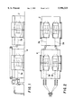
- FIG. 1 is a side view of an installation comprising four machines according to the invention and making it possible to obtain a cable that consists of four pairs of wires.
- FIG. 2 is a view of this machine from above.
- FIG. 3 is a view from above and in part section of the machine according to the invention.
- FIG. 4 is a view in perspective diagrammatically illustrating the path taken by the wires inside the machine.
- FIG. 1 depicts an installation comprising four machines grouped in pairs.
- the two groups of machines are aligned axially with respect to each other.
- Each machine 2 of a first group makes it possible to obtain a pair of wires 3a twisted together.
- These wires 3a pass over the group comprising the two machines 4.
- the two machines 4 supply two pairs of wires 3b which are guided parallel to the wires 3a to be twisted together with these wires at a station which has not been depicted in the drawings.
- Each machine comprises a bed 5 on which there are mounted so that they can pivot, by means of bearings 7, two coaxial hollow shafts.
- the hollow shafts are rotated by belts 8 off a drive shaft 9.
- the two hollow shafts 6 are connected by a bent piece 10 forming a lyre, equipped with means for guiding wires and twisting them together.
- Mounted on the hollow shafts 6 with the insertion of bearings 13 is a large cradle 12 placed inside the volume defined by the large lyre 10 as it rotates.
- the large cradle 12 does not rotate about its axis.
- This large cradle 12 has at least one.
- each small lyre 15 is mounted via two coaxial supports 16 on the large cradle 12 and on the cross member 14 thereof respectively, with the insertion of rolling bearings 17.
- Each small lyre 15 is rotated off a hollow shaft 6 using a first belt 18 passing around the hollow shaft and driving a secondary shaft 19 which itself drives a belt 20 fixed to a support 16 of the small lyre.
- Placed inside each small lyre 15 is a small cradle 22.
- Each small cradle is mounted on the supports 16 of the corresponding small lyre 15 with the insertion of rolling bearings 23.
- Each small cradle 22 is used to mount a reel 24.
- the small cradle has a stationary spike on one side, over which the reel is engaged, and on the other side has a spike 25 which can be shifted axially by means of a pinion 26 meshing with a rack in order either to cause the reel to be clamped by the spike 25 or, on the other hand, to retract this same spike.
- each reel 24 is offset with respect to the axis common to the hollow shafts, the large cradle, the small lyres and the small cradles. Power is supplied to each electric motor 27, and the movement of each reel is controlled, by means of commutators 30 mounted on the rotating parts and rubbing on brushes secured to the stationary parts opposite them.
- each wire starting from a reel 24 is as follows: the wire 31 passes over a wire-guiding roller 32 then over pulleys 33 which lead the wire axially and outward over a small lyre 15.
- the wire follows this small lyre and is twisted, bearing in mind the rotation of this small lyre, in such a way that it leaves axially inward.
- the two wires paid out from the two reels pass over parallel pulleys 34, then over jumping-jack mechanisms 35 that regulate the tension of the wire, and are guided in parallel over pulleys 36 secured to the large cradle.
- the two parallel wires emerge axially from the large cradle 12 and are then taken up by the large lyre 10 which they follow along its entire length, before re-emerging axially at the other end of the machine.
- the movement of the two wires as they travel along, combined with the rotational movement of the large lyre causes these two wires to be twisted together.
- the small lyre 15 lying in the compartment on the right-hand side of the drawing rotates in the opposite direction to the large lyre, while the small lyre 15 lying in the compartment on the left-hand side rotates in the same direction as the large lyre.
- the invention provides a great improvement to the existing state of the art by providing a machine which allows twisted-together wires to be obtained in a single operation, with it being possible for the torsion of these wires to be removed before they are twisted together.
- the invention is not limited merely to the embodiment of this machine which has been described hereinabove by way of example; on the contrary, it encompasses all alternative forms thereof.
- the shape of the lyres, the layout of the reels could be different, or alternatively, the means of driving the small lyres could be different, without this in any way departing from the scope of the invention.
Landscapes
- Engineering & Computer Science (AREA)
- Manufacturing & Machinery (AREA)
- Mechanical Engineering (AREA)
- Processes Specially Adapted For Manufacturing Cables (AREA)
- Manufacturing Of Electrical Connectors (AREA)
- Ropes Or Cables (AREA)
- Wire Processing (AREA)
Applications Claiming Priority (2)
| Application Number | Priority Date | Filing Date | Title |
|---|---|---|---|
| FR9701241 | 1997-01-30 | ||
| FR9701241A FR2758902B1 (fr) | 1997-01-30 | 1997-01-30 | Machine d'assemblage par torsion de cables conducteurs |
Publications (1)
| Publication Number | Publication Date |
|---|---|
| US5996325A true US5996325A (en) | 1999-12-07 |
Family
ID=9503305
Family Applications (1)
| Application Number | Title | Priority Date | Filing Date |
|---|---|---|---|
| US09/015,401 Expired - Fee Related US5996325A (en) | 1997-01-30 | 1998-01-29 | Machine for twisting conductor cables together |
Country Status (8)
| Country | Link |
|---|---|
| US (1) | US5996325A (de) |
| EP (1) | EP0858083A1 (de) |
| KR (1) | KR19980070834A (de) |
| CN (1) | CN1193802A (de) |
| CA (1) | CA2228327C (de) |
| FR (1) | FR2758902B1 (de) |
| SG (1) | SG60188A1 (de) |
| TW (1) | TW411644B (de) |
Cited By (2)
| Publication number | Priority date | Publication date | Assignee | Title |
|---|---|---|---|---|
| US20050034443A1 (en) * | 2003-08-14 | 2005-02-17 | Cook Thomas Christopher | Optical fibers twinning apparatus and process |
| CN113161073A (zh) * | 2021-02-25 | 2021-07-23 | 通盈电业(深圳)有限公司 | 电缆对绞机 |
Families Citing this family (3)
| Publication number | Priority date | Publication date | Assignee | Title |
|---|---|---|---|---|
| US6167687B1 (en) * | 1998-02-11 | 2001-01-02 | Nextrom Ltd. | Group twinner for single and double conductor bobbins and method of making communication cables |
| FR2884036B1 (fr) * | 2005-04-01 | 2007-05-18 | Eurocopter France | Outillage pour la fabrication de harnais rigides a grosses sections |
| CN110550498A (zh) * | 2018-12-29 | 2019-12-10 | 上海理工大学 | 自动拉卷分切毛条机设备 |
Citations (7)
| Publication number | Priority date | Publication date | Assignee | Title |
|---|---|---|---|---|
| CH450232A (fr) * | 1963-04-12 | 1968-01-15 | Delore Sa Geoffroy | Procédé de câblage à double torsion et installation pour la mise en oeuvre de ce procédé |
| DE2052705A1 (de) * | 1969-10-27 | 1971-05-13 | Akachi Hisateru | Kabel und Vorrichtung und Verfahren zur Herstellung eines Kabels |
| US3791131A (en) * | 1972-03-27 | 1974-02-12 | R Scott | Method of making a concentric wire rope on a double twist strander |
| US3867809A (en) * | 1972-10-02 | 1975-02-25 | Morgan Construction Co | Double twist wire stranding machine with removable creel assembly |
| CH608254A5 (en) * | 1977-02-02 | 1978-12-29 | Maillefer Sa | Stranding machine comprising a cable regulating device and a cradle |
| US5564268A (en) * | 1994-04-08 | 1996-10-15 | Ceeco Machinery Manufacturing Ltd. | Apparatus and method for the manufacture of uniform impedance communication cables for high frequency use |
| US5622039A (en) * | 1994-04-08 | 1997-04-22 | Ceeco Machinery Manufacturing Limited | Apparatus and method for the manufacture of uniform impedance communications cables for high frequency use |
-
1997
- 1997-01-30 FR FR9701241A patent/FR2758902B1/fr not_active Expired - Fee Related
-
1998
- 1998-01-23 SG SG1998000166A patent/SG60188A1/en unknown
- 1998-01-24 KR KR1019980002262A patent/KR19980070834A/ko not_active Application Discontinuation
- 1998-01-26 TW TW087101070A patent/TW411644B/zh not_active IP Right Cessation
- 1998-01-26 CN CN98106188A patent/CN1193802A/zh active Pending
- 1998-01-28 EP EP98420018A patent/EP0858083A1/de not_active Withdrawn
- 1998-01-29 CA CA002228327A patent/CA2228327C/fr not_active Expired - Fee Related
- 1998-01-29 US US09/015,401 patent/US5996325A/en not_active Expired - Fee Related
Patent Citations (7)
| Publication number | Priority date | Publication date | Assignee | Title |
|---|---|---|---|---|
| CH450232A (fr) * | 1963-04-12 | 1968-01-15 | Delore Sa Geoffroy | Procédé de câblage à double torsion et installation pour la mise en oeuvre de ce procédé |
| DE2052705A1 (de) * | 1969-10-27 | 1971-05-13 | Akachi Hisateru | Kabel und Vorrichtung und Verfahren zur Herstellung eines Kabels |
| US3791131A (en) * | 1972-03-27 | 1974-02-12 | R Scott | Method of making a concentric wire rope on a double twist strander |
| US3867809A (en) * | 1972-10-02 | 1975-02-25 | Morgan Construction Co | Double twist wire stranding machine with removable creel assembly |
| CH608254A5 (en) * | 1977-02-02 | 1978-12-29 | Maillefer Sa | Stranding machine comprising a cable regulating device and a cradle |
| US5564268A (en) * | 1994-04-08 | 1996-10-15 | Ceeco Machinery Manufacturing Ltd. | Apparatus and method for the manufacture of uniform impedance communication cables for high frequency use |
| US5622039A (en) * | 1994-04-08 | 1997-04-22 | Ceeco Machinery Manufacturing Limited | Apparatus and method for the manufacture of uniform impedance communications cables for high frequency use |
Cited By (3)
| Publication number | Priority date | Publication date | Assignee | Title |
|---|---|---|---|---|
| US20050034443A1 (en) * | 2003-08-14 | 2005-02-17 | Cook Thomas Christopher | Optical fibers twinning apparatus and process |
| CN113161073A (zh) * | 2021-02-25 | 2021-07-23 | 通盈电业(深圳)有限公司 | 电缆对绞机 |
| CN113161073B (zh) * | 2021-02-25 | 2022-09-02 | 通盈电业(深圳)有限公司 | 电缆对绞机 |
Also Published As
| Publication number | Publication date |
|---|---|
| SG60188A1 (en) | 1999-02-22 |
| CA2228327A1 (fr) | 1998-07-30 |
| CN1193802A (zh) | 1998-09-23 |
| EP0858083A1 (de) | 1998-08-12 |
| FR2758902A1 (fr) | 1998-07-31 |
| TW411644B (en) | 2000-11-11 |
| KR19980070834A (ko) | 1998-10-26 |
| CA2228327C (fr) | 2001-07-10 |
| FR2758902B1 (fr) | 1999-04-09 |
Similar Documents
| Publication | Publication Date | Title |
|---|---|---|
| US3715877A (en) | Communication cable | |
| US5996325A (en) | Machine for twisting conductor cables together | |
| CN209785645U (zh) | 一种电缆芯捻合装置 | |
| CN112875420A (zh) | 一种纤维加捻收卷装置 | |
| US4704855A (en) | Wire twisting device | |
| US2941348A (en) | Manufacture of wire strands, bunches, and cables | |
| US4214432A (en) | Apparatus for forming S-Z twisted strand units | |
| US1988586A (en) | Quad stranding machine | |
| US4590754A (en) | Forming cable core units | |
| US4604862A (en) | Manufacture of telecommunications cable cores | |
| US3413793A (en) | Sheave capstan assembly for cable takeup apparatus | |
| CN211237825U (zh) | 一种高速绞线机 | |
| JP5004287B2 (ja) | 撚線機およびそれを用いた撚線の製造方法 | |
| US5161359A (en) | Cable stranding apparatus | |
| KR102129180B1 (ko) | 전선 트위스트 장치 | |
| SU1589326A1 (ru) | Устройство дл разнонаправленной скрутки проволок или проводов | |
| EP0461844A2 (de) | Verbesserungen an Vorseilmaschinen | |
| CA1217395A (en) | Forming cable core units | |
| JPH0438914Y2 (de) | ||
| US1981134A (en) | Apparatus for twisting strands | |
| EP0147071B1 (de) | Herstellung von Nachrichtenkabelseelen | |
| CN118136342A (zh) | 一种用于汽车线束的均匀缠带装置 | |
| WO1999063147A1 (en) | Cable twist setting method and apparatus | |
| JPS6110928B2 (de) | ||
| CA1217251A (en) | Core unit for a telecommunications cable |
Legal Events
| Date | Code | Title | Description |
|---|---|---|---|
| AS | Assignment |
Owner name: SOCIETE NOUVELLE SETIC SA ZONE INDUSTRIELLE DE MAT Free format text: ASSIGNMENT OF ASSIGNORS INTEREST;ASSIGNORS:GAUDER, EDGAR;BAYARD, PHILIPPE;PERRIER, SERGE;AND OTHERS;REEL/FRAME:009133/0936;SIGNING DATES FROM 19980227 TO 19980306 |
|
| REMI | Maintenance fee reminder mailed | ||
| LAPS | Lapse for failure to pay maintenance fees | ||
| FP | Lapsed due to failure to pay maintenance fee |
Effective date: 20031207 |
|
| STCH | Information on status: patent discontinuation |
Free format text: PATENT EXPIRED DUE TO NONPAYMENT OF MAINTENANCE FEES UNDER 37 CFR 1.362 |