EP0461844A2 - Verbesserungen an Vorseilmaschinen - Google Patents
Verbesserungen an Vorseilmaschinen Download PDFInfo
- Publication number
- EP0461844A2 EP0461844A2 EP91305231A EP91305231A EP0461844A2 EP 0461844 A2 EP0461844 A2 EP 0461844A2 EP 91305231 A EP91305231 A EP 91305231A EP 91305231 A EP91305231 A EP 91305231A EP 0461844 A2 EP0461844 A2 EP 0461844A2
- Authority
- EP
- European Patent Office
- Prior art keywords
- flyer
- path
- guide
- rotate
- axis
- Prior art date
- Legal status (The legal status is an assumption and is not a legal conclusion. Google has not performed a legal analysis and makes no representation as to the accuracy of the status listed.)
- Granted
Links
Images


Classifications
-
- D—TEXTILES; PAPER
- D07—ROPES; CABLES OTHER THAN ELECTRIC
- D07B—ROPES OR CABLES IN GENERAL
- D07B3/00—General-purpose machines or apparatus for producing twisted ropes or cables from component strands of the same or different material
- D07B3/08—General-purpose machines or apparatus for producing twisted ropes or cables from component strands of the same or different material in which the take-up reel rotates about the axis of the rope or cable or in which a guide member rotates about the axis of the rope or cable to guide the rope or cable on the take-up reel in fixed position and the supply reels are fixed in position
- D07B3/10—General-purpose machines or apparatus for producing twisted ropes or cables from component strands of the same or different material in which the take-up reel rotates about the axis of the rope or cable or in which a guide member rotates about the axis of the rope or cable to guide the rope or cable on the take-up reel in fixed position and the supply reels are fixed in position with provision for imparting more than one complete twist to the ropes or cables for each revolution of the take-up reel or of the guide member
- D07B3/103—General-purpose machines or apparatus for producing twisted ropes or cables from component strands of the same or different material in which the take-up reel rotates about the axis of the rope or cable or in which a guide member rotates about the axis of the rope or cable to guide the rope or cable on the take-up reel in fixed position and the supply reels are fixed in position with provision for imparting more than one complete twist to the ropes or cables for each revolution of the take-up reel or of the guide member characterised by the bow construction
-
- D—TEXTILES; PAPER
- D07—ROPES; CABLES OTHER THAN ELECTRIC
- D07B—ROPES OR CABLES IN GENERAL
- D07B3/00—General-purpose machines or apparatus for producing twisted ropes or cables from component strands of the same or different material
- D07B3/08—General-purpose machines or apparatus for producing twisted ropes or cables from component strands of the same or different material in which the take-up reel rotates about the axis of the rope or cable or in which a guide member rotates about the axis of the rope or cable to guide the rope or cable on the take-up reel in fixed position and the supply reels are fixed in position
- D07B3/10—General-purpose machines or apparatus for producing twisted ropes or cables from component strands of the same or different material in which the take-up reel rotates about the axis of the rope or cable or in which a guide member rotates about the axis of the rope or cable to guide the rope or cable on the take-up reel in fixed position and the supply reels are fixed in position with provision for imparting more than one complete twist to the ropes or cables for each revolution of the take-up reel or of the guide member
-
- D—TEXTILES; PAPER
- D07—ROPES; CABLES OTHER THAN ELECTRIC
- D07B—ROPES OR CABLES IN GENERAL
- D07B7/00—Details of, or auxiliary devices incorporated in, rope- or cable-making machines; Auxiliary apparatus associated with such machines
- D07B7/02—Machine details; Auxiliary devices
Definitions
- This invention concerns improvements in and relating to stranding machines and more especially to such a machine for production of cable which is of complex section and/or large dimension at higher speed than has hitherto been possible.
- the elements of the cable or rope can be fed from separate supply bobbins to a stranding head at which they are laid up to form the cable or rope, a twist or "lay” being imparted to the cable or rope by the rotation of an appropriate haul-off device.
- the fact that the cable leaving the haul-off device is rotating about its longitudinal axis requires that the final storage bobbin or reel upon which the cable or rope is to be wound must be rotated at the same speed.
- This system has the advantage that a perfectly formed cable can be produced.
- the so-called "double-twist" stranding machine In the second system, the so-called "double-twist" stranding machine, the path of the cable is led along a rotary flyer carrying the cable to a winding bobbin which is inside the envelope of the rotating flyer.
- This bobbin is rotated only about its own axis for winding, but is otherwise stationary and thus does not cause the above mentioned stresses and limitations due to the rotating masses.
- double-twist stranding machine is not applicable to the production of cables of high quality and/or of complex section, because the second twist disorders the sectional shape of the cable that has been formed in the first.
- the present invention is based on the concept that it would be desirable to combine the features of the two systems referred to, so that the cable section and lay is formed by a rotating haul-off die, as in the single twist machine, with the haul-off providing the pulling force required in the stranding operation, and an in-line double twist -machine serving solely as a means for taking up the cable onto a stationary winding bobbin.
- the present invention is further based upon the appreciation by the present applicants that in order to effect a practical combination of such devices, some means must be provided to enable the flyer of the double twist machine to rotate at substantially one half the speed of the haul-off device without the normal cable guides thereof exerting a back-twist on the cable, so that the cable can continue to rotate at the speed of the haul-off device without the lay thereof tending to become disturbed by the tangential friction between the cable and the guides of the flyer.
- a method of transporting an elongate element through a flyer arranged to rotate about an axis coinciding with a longitudinal path of said element externally of the flyer characterised in that the said element is driven to rotate about its own axis relatively to the flyer, at at least one point on its path within said flyer, in order substantially to maintain that section of said element guided within the flyer at the same relative angular position about its own axis as a section thereof that is located on said longitudinal path.
- the said flyer is arranged to rotate around a bobbin or reel onto which said element is to be wound and the path of the said element is turned through 180° within said flyer, whereby rotation of said element on said longitudinal path is cancelled at the point at which it is led to the bobbin or reel.
- the invention further provides an apparatus for carrying out the method of the invention, comprising a flyer arranged to rotate around about a predetermined axis, guide means extending within said flyer and arranged to guide an elongate element along a path therein and means for driving said guide means to rotate relatively to the flyer in order to cause corresponding rotation of said element.
- the arrangement is such that said element is transported via said flyer from an axial path externally of said flyer and about which it is arranged to rotate, to a bobbin or reel located within said flyer, along a path extending therein through an angle of 180°, the said guide means and the flyer being arranged to rotate at such relative speeds that the rotation of the element is cancelled at the point at which it is led from the flyer to the bobbin.
- the haul-off device 1 is driven to rotate about the axis of the path 4 at a rotary speed to which the linear speed of the finished rope must be related in such a manner as to introduce into the rope the desired length of lay.
- the device 6 incorporates a storage bobbin or reel indicated diagrammatically at 7 which is arranged to rotate about its own axis 8 as required to take up the finished rope, but is otherwise stationary.
- the finished rope passes from its axial path 4, along which it leaves the rotating haul-off device 1, to the reel 7 along a path indicated diagrammatically at 9, proceeding in the direction indicated by the arrow heads 10.
- the rope passes through a flyer indicated diagrammatically at 11 in Fig.1, held by supports 23 and 24 arranged to rotate in mountings indicated at 12 in Fig.1.
- a flyer indicated diagrammatically at 11 in Fig.1, held by supports 23 and 24 arranged to rotate in mountings indicated at 12 in Fig.1.
- the path 9 of the rope it will be seen that as the rope passes through the flyer 11 it is diverted from its linear path 4 at the point 9A, passes through the flyer along a part 9B of the path 9 radially spaced from the rotational axis of the flyer 11 and is then turned through 180° in a region 9C before exiting from the flyer 11 at a point 9D.
- reel 7 and the path of the rope thereto is shown only diagrammatically in Fig.1, it will be appreciated that the bobbin 7 and an associated means for guiding and layering the rope onto the bobbin or reel can be supported by appropriate means 11 in such a manner that the flyer 11 can rotate around the bobbin or reel 7 whilst the latter and the associated guide means remain stationary.
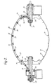
- the flyer 11 is of the so-called "bow" type. That is to say that the portion of the flyer carrying the rope is formed as a flexible strap or bow 20, ends 21 and 22 of which are anchored to hubs 23 and 24 that are mounted for rotation in bearings 26 of the mountings 12.
- the bow 20 carries on its internal surface a series of ball races 27 within which are mounted tubes 28 for supporting guide rollers 29 for receiving the rope.
- the tubes 28 and the guide rollers 29 may be free to rotate with the rope, or may be driven by means not shown to rotate at the same speed as the rope.
- the bow 20 is counterbalanced by a matching bow 30 carrying balancing weights 31 having a mass corresponding to that of the elements 27, 28, 29 of the bow 20.
- the hub 23 at the left hand end of the flyer in Fig. 2 carries a rope guide means in the form of a shaft 32 the left hand end 33 of which is mounted coaxially within the hub 23 and the right hand end 34 of which is linked to the hub 23 at a point adjacent the bow 20 in such a manner as to allow rotation of the shaft about its own axis.
- the hollow shaft 32 is articulated by means of universal joints in such a manner that the whole shaft can be driven for rotation from its left hand end, in order to transmit corresponding rotation to the rope sliding within the shaft via rollers 35 carried in the segments of the shaft.
- the right hand hub 24 of the flyer 11 likewise carries a hollow shaft 36 that is articulated in a similar manner to the shaft 32 and which also has a series of rollers.
- the shaft 36 like the shaft 32, is mounted in the hub 24 so that it can rotate relatively thereto about its own axis, but its extremity 37 is nevertheless fixed to the stationary support of the take up bobbin 7 and cannot rotate.
- the rope passes from the shaft 36 to the take up bobbin along the path shown in Fig 1.
- the drive to the various elements of the device includes a main drive motor 40 which is arranged to drive the haul-off device 1, the shaft 32 and the hubs 23 and 24 of the flyer 6 from a common shaft via gear trains 41, 42 and 43 respectively, the ratio of the trains 42 and 43 being one half of that of the train 41 so that the flyer 6 is rotated at the appropriate speed.
- a motor 45 drives the capstans 2 and 3 in known manner.
- Motors 46 and 47 of a common take-up unit not illustrated in detail and held stationary on bearings coaxial with the bearings of the flyer 6 by means of a counterweight, serve to rotate the bobbin 7 and to drive a traverse for layering the cable on to the bobbin.
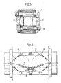
- Fig.6. is shown furthermore how the tendency of the cable to leave the haul-off capstan, due to the centrifugal force, can be prevented.
- a set of rollers or a pre-tensioned continous belt 52 press the cable against the capstan; sets of rollers 53, 54 prevent the cable moving away from the right path.
- the shaft 32 could be extended over the full axial length of the cradle to point 37 and fixed at that extremity with respect to the bobbin or the shaft 36 could be extended to point 33 and, at that point, be left free to rotate.
Landscapes
- Ropes Or Cables (AREA)
- Glass Compositions (AREA)
- Disintegrating Or Milling (AREA)
- Preparation Of Compounds By Using Micro-Organisms (AREA)
- Braiding, Manufacturing Of Bobbin-Net Or Lace, And Manufacturing Of Nets By Knotting (AREA)
Applications Claiming Priority (4)
| Application Number | Priority Date | Filing Date | Title |
|---|---|---|---|
| GB9013006 | 1990-06-11 | ||
| GB909013006A GB9013006D0 (en) | 1990-06-11 | 1990-06-11 | Improvements in and relating to stranding machines |
| GB9019746 | 1990-09-10 | ||
| GB909019746A GB9019746D0 (en) | 1990-09-10 | 1990-09-10 | Improvements in and relating to stranding machines |
Publications (3)
| Publication Number | Publication Date |
|---|---|
| EP0461844A2 true EP0461844A2 (de) | 1991-12-18 |
| EP0461844A3 EP0461844A3 (en) | 1992-07-15 |
| EP0461844B1 EP0461844B1 (de) | 1996-12-11 |
Family
ID=26297188
Family Applications (1)
| Application Number | Title | Priority Date | Filing Date |
|---|---|---|---|
| EP91305231A Expired - Lifetime EP0461844B1 (de) | 1990-06-11 | 1991-06-11 | Verbesserungen an Vorseilmaschinen |
Country Status (5)
| Country | Link |
|---|---|
| EP (1) | EP0461844B1 (de) |
| AT (1) | ATE146237T1 (de) |
| DE (1) | DE69123491T2 (de) |
| ES (1) | ES2098324T3 (de) |
| IT (1) | IT1261027B (de) |
Cited By (4)
| Publication number | Priority date | Publication date | Assignee | Title |
|---|---|---|---|---|
| EP0564921A1 (de) * | 1992-04-07 | 1993-10-13 | ALCATEL CAVI S.p.A. | Rotor für Kabelverseilmaschine |
| FR2703081A1 (fr) * | 1993-03-22 | 1994-09-30 | Rollin Pere Fils | Ensemble rotatif d'entraînement d'un toron ou câble, destiné à une installation de câblage et/ou de rubannage en ligne ou de fabrication de cordage. |
| US5540041A (en) * | 1994-09-13 | 1996-07-30 | Southwire Company | Method of and apparatus for stress relieving multistranded cable |
| EP1441063A1 (de) * | 2003-01-24 | 2004-07-28 | Officine Meccaniche di Lesmo S.p.A. | Doppelschlagverseilmaschine |
Citations (4)
| Publication number | Priority date | Publication date | Assignee | Title |
|---|---|---|---|---|
| DE543939C (de) * | 1929-10-29 | 1932-02-11 | Stadtgemeinde Olpe | Schnellverseilmaschine |
| DE2118967A1 (de) * | 1971-04-20 | 1972-10-26 | Kraft, Anton, 5960 Olpe | Vielfachschlag , insbesondere Doppelschlag Verseilmaschine |
| GB2088921A (en) * | 1980-12-05 | 1982-06-16 | Redaelli Tecna Spa | Stranding machine |
| DE3802631A1 (de) * | 1988-01-29 | 1989-08-10 | Sevastopol Priborostroit Inst | Verfahren zur herstellung von metallischen verseilten erzeugnissen |
-
1991
- 1991-06-11 ES ES91305231T patent/ES2098324T3/es not_active Expired - Lifetime
- 1991-06-11 AT AT91305231T patent/ATE146237T1/de not_active IP Right Cessation
- 1991-06-11 EP EP91305231A patent/EP0461844B1/de not_active Expired - Lifetime
- 1991-06-11 DE DE69123491T patent/DE69123491T2/de not_active Expired - Fee Related
- 1991-06-11 IT ITMI911599A patent/IT1261027B/it active IP Right Grant
Patent Citations (5)
| Publication number | Priority date | Publication date | Assignee | Title |
|---|---|---|---|---|
| DE543939C (de) * | 1929-10-29 | 1932-02-11 | Stadtgemeinde Olpe | Schnellverseilmaschine |
| DE668371C (de) * | 1929-10-29 | 1938-12-01 | Stadtgemeinde Olpe | Schnellverseilmaschine |
| DE2118967A1 (de) * | 1971-04-20 | 1972-10-26 | Kraft, Anton, 5960 Olpe | Vielfachschlag , insbesondere Doppelschlag Verseilmaschine |
| GB2088921A (en) * | 1980-12-05 | 1982-06-16 | Redaelli Tecna Spa | Stranding machine |
| DE3802631A1 (de) * | 1988-01-29 | 1989-08-10 | Sevastopol Priborostroit Inst | Verfahren zur herstellung von metallischen verseilten erzeugnissen |
Cited By (4)
| Publication number | Priority date | Publication date | Assignee | Title |
|---|---|---|---|---|
| EP0564921A1 (de) * | 1992-04-07 | 1993-10-13 | ALCATEL CAVI S.p.A. | Rotor für Kabelverseilmaschine |
| FR2703081A1 (fr) * | 1993-03-22 | 1994-09-30 | Rollin Pere Fils | Ensemble rotatif d'entraînement d'un toron ou câble, destiné à une installation de câblage et/ou de rubannage en ligne ou de fabrication de cordage. |
| US5540041A (en) * | 1994-09-13 | 1996-07-30 | Southwire Company | Method of and apparatus for stress relieving multistranded cable |
| EP1441063A1 (de) * | 2003-01-24 | 2004-07-28 | Officine Meccaniche di Lesmo S.p.A. | Doppelschlagverseilmaschine |
Also Published As
| Publication number | Publication date |
|---|---|
| EP0461844A3 (en) | 1992-07-15 |
| ATE146237T1 (de) | 1996-12-15 |
| ITMI911599A1 (it) | 1992-12-11 |
| DE69123491D1 (de) | 1997-01-23 |
| DE69123491T2 (de) | 1997-06-12 |
| IT1261027B (it) | 1996-05-08 |
| ES2098324T3 (es) | 1997-05-01 |
| ITMI911599A0 (it) | 1991-06-11 |
| EP0461844B1 (de) | 1996-12-11 |
Similar Documents
| Publication | Publication Date | Title |
|---|---|---|
| US3715877A (en) | Communication cable | |
| US3884024A (en) | Twisting device for the SZ twisting of electrical cables | |
| US5263309A (en) | Method of and apparatus for balancing the load of a cabling apparatus | |
| US3828538A (en) | High-speed double twist twisting apparatus mainly adapted to twist steel wires | |
| US3431718A (en) | Method and machines for twisting together strands of material | |
| US3091074A (en) | Apparatus for producing communication cables | |
| US4704855A (en) | Wire twisting device | |
| US5400579A (en) | Apparatus and method for the manufacture of telephone cables | |
| EP0461844B1 (de) | Verbesserungen an Vorseilmaschinen | |
| US3138914A (en) | Wire closing machine | |
| US3388543A (en) | Manufacture of wire strands | |
| US4300339A (en) | System for stranding and cabling elongate filaments | |
| US6286294B1 (en) | Wire stranding machine | |
| US4570428A (en) | Twin track buncher | |
| US4549394A (en) | Stranding device for stranding machines, particularly a pre-twist and drafting device | |
| CA2044352A1 (en) | Stranding machines | |
| CA2461601C (en) | Flyer bow apparatus with traveling carrier strip | |
| US3271942A (en) | Apparatus for the making of strands, ropes, cables and the like | |
| AU589572B2 (en) | Double twist bow buncher | |
| CN111952012B (zh) | 双臂高速绞线机 | |
| US1906543A (en) | Stranding | |
| GB2052585A (en) | Stranding Apparatus for Manufacturing Multi-layer Steel Cables, Particularly Steel Cord | |
| CA1283023C (en) | Wire twisting equipment | |
| CA1227705A (en) | Apparatus and method of making metallic cord | |
| JPS5921467Y2 (ja) | 撚線機 |
Legal Events
| Date | Code | Title | Description |
|---|---|---|---|
| PUAI | Public reference made under article 153(3) epc to a published international application that has entered the european phase |
Free format text: ORIGINAL CODE: 0009012 |
|
| AK | Designated contracting states |
Kind code of ref document: A2 Designated state(s): AT BE CH DE DK ES FR GB IT LI NL SE |
|
| PUAL | Search report despatched |
Free format text: ORIGINAL CODE: 0009013 |
|
| AK | Designated contracting states |
Kind code of ref document: A3 Designated state(s): AT BE CH DE DK ES FR GB IT LI NL SE |
|
| 17P | Request for examination filed |
Effective date: 19921223 |
|
| 17Q | First examination report despatched |
Effective date: 19950317 |
|
| ITCL | It: translation for ep claims filed |
Representative=s name: FRANCO CICOGNA |
|
| GRAG | Despatch of communication of intention to grant |
Free format text: ORIGINAL CODE: EPIDOS AGRA |
|
| GRAH | Despatch of communication of intention to grant a patent |
Free format text: ORIGINAL CODE: EPIDOS IGRA |
|
| GRAH | Despatch of communication of intention to grant a patent |
Free format text: ORIGINAL CODE: EPIDOS IGRA |
|
| GRAA | (expected) grant |
Free format text: ORIGINAL CODE: 0009210 |
|
| AK | Designated contracting states |
Kind code of ref document: B1 Designated state(s): AT BE CH DE DK ES FR GB IT LI NL SE |
|
| PG25 | Lapsed in a contracting state [announced via postgrant information from national office to epo] |
Ref country code: NL Free format text: LAPSE BECAUSE OF FAILURE TO SUBMIT A TRANSLATION OF THE DESCRIPTION OR TO PAY THE FEE WITHIN THE PRESCRIBED TIME-LIMIT Effective date: 19961211 Ref country code: LI Effective date: 19961211 Ref country code: DK Effective date: 19961211 Ref country code: CH Effective date: 19961211 Ref country code: AT Effective date: 19961211 |
|
| REF | Corresponds to: |
Ref document number: 146237 Country of ref document: AT Date of ref document: 19961215 Kind code of ref document: T |
|
| ITF | It: translation for a ep patent filed |
Owner name: DOTT. FRANCO CICOGNA |
|
| REF | Corresponds to: |
Ref document number: 69123491 Country of ref document: DE Date of ref document: 19970123 |
|
| ET | Fr: translation filed | ||
| PG25 | Lapsed in a contracting state [announced via postgrant information from national office to epo] |
Ref country code: SE Effective date: 19970311 |
|
| NLV1 | Nl: lapsed or annulled due to failure to fulfill the requirements of art. 29p and 29m of the patents act | ||
| REG | Reference to a national code |
Ref country code: ES Ref legal event code: FG2A Ref document number: 2098324 Country of ref document: ES Kind code of ref document: T3 |
|
| REG | Reference to a national code |
Ref country code: CH Ref legal event code: PL |
|
| K2C3 | Correction of patent specification (complete document) published |
Effective date: 19961211 |
|
| PLBE | No opposition filed within time limit |
Free format text: ORIGINAL CODE: 0009261 |
|
| STAA | Information on the status of an ep patent application or granted ep patent |
Free format text: STATUS: NO OPPOSITION FILED WITHIN TIME LIMIT |
|
| 26N | No opposition filed | ||
| REG | Reference to a national code |
Ref country code: GB Ref legal event code: IF02 |
|
| PGFP | Annual fee paid to national office [announced via postgrant information from national office to epo] |
Ref country code: GB Payment date: 20040525 Year of fee payment: 14 |
|
| PGFP | Annual fee paid to national office [announced via postgrant information from national office to epo] |
Ref country code: BE Payment date: 20040528 Year of fee payment: 14 |
|
| PG25 | Lapsed in a contracting state [announced via postgrant information from national office to epo] |
Ref country code: IT Free format text: LAPSE BECAUSE OF NON-PAYMENT OF DUE FEES;WARNING: LAPSES OF ITALIAN PATENTS WITH EFFECTIVE DATE BEFORE 2007 MAY HAVE OCCURRED AT ANY TIME BEFORE 2007. THE CORRECT EFFECTIVE DATE MAY BE DIFFERENT FROM THE ONE RECORDED. Effective date: 20050611 Ref country code: GB Free format text: LAPSE BECAUSE OF NON-PAYMENT OF DUE FEES Effective date: 20050611 |
|
| PGFP | Annual fee paid to national office [announced via postgrant information from national office to epo] |
Ref country code: FR Payment date: 20050629 Year of fee payment: 15 Ref country code: ES Payment date: 20050629 Year of fee payment: 15 |
|
| PG25 | Lapsed in a contracting state [announced via postgrant information from national office to epo] |
Ref country code: BE Free format text: LAPSE BECAUSE OF NON-PAYMENT OF DUE FEES Effective date: 20050630 |
|
| PGFP | Annual fee paid to national office [announced via postgrant information from national office to epo] |
Ref country code: DE Payment date: 20050630 Year of fee payment: 15 |
|
| GBPC | Gb: european patent ceased through non-payment of renewal fee |
Effective date: 20050611 |
|
| PG25 | Lapsed in a contracting state [announced via postgrant information from national office to epo] |
Ref country code: ES Free format text: LAPSE BECAUSE OF NON-PAYMENT OF DUE FEES Effective date: 20060612 |
|
| PG25 | Lapsed in a contracting state [announced via postgrant information from national office to epo] |
Ref country code: DE Free format text: LAPSE BECAUSE OF NON-PAYMENT OF DUE FEES Effective date: 20070103 |
|
| REG | Reference to a national code |
Ref country code: FR Ref legal event code: ST Effective date: 20070228 |
|
| REG | Reference to a national code |
Ref country code: ES Ref legal event code: FD2A Effective date: 20060612 |
|
| BERE | Be: lapsed |
Owner name: *CORTINOVIS S.P.A. Effective date: 20050630 |
|
| PG25 | Lapsed in a contracting state [announced via postgrant information from national office to epo] |
Ref country code: FR Free format text: LAPSE BECAUSE OF NON-PAYMENT OF DUE FEES Effective date: 20060630 |