US5941837A - Health management device and exercise support device - Google Patents
Health management device and exercise support device Download PDFInfo
- Publication number
- US5941837A US5941837A US08/894,457 US89445797A US5941837A US 5941837 A US5941837 A US 5941837A US 89445797 A US89445797 A US 89445797A US 5941837 A US5941837 A US 5941837A
- Authority
- US
- United States
- Prior art keywords
- exercise
- user
- value
- pulse
- indicator
- Prior art date
- Legal status (The legal status is an assumption and is not a legal conclusion. Google has not performed a legal analysis and makes no representation as to the accuracy of the status listed.)
- Expired - Lifetime
Links
- 230000036541 health Effects 0.000 title claims abstract description 95
- 230000001133 acceleration Effects 0.000 claims abstract description 130
- 230000008859 change Effects 0.000 claims description 49
- 238000011156 evaluation Methods 0.000 claims description 39
- 230000033001 locomotion Effects 0.000 claims description 37
- 238000010183 spectrum analysis Methods 0.000 claims description 20
- 230000003595 spectral effect Effects 0.000 claims description 12
- 238000005259 measurement Methods 0.000 abstract description 51
- 238000012549 training Methods 0.000 description 38
- 238000000034 method Methods 0.000 description 37
- 230000006854 communication Effects 0.000 description 29
- 238000004891 communication Methods 0.000 description 29
- 238000012545 processing Methods 0.000 description 29
- 230000000875 corresponding effect Effects 0.000 description 28
- QVGXLLKOCUKJST-UHFFFAOYSA-N atomic oxygen Chemical compound [O] QVGXLLKOCUKJST-UHFFFAOYSA-N 0.000 description 27
- 239000001301 oxygen Substances 0.000 description 27
- 229910052760 oxygen Inorganic materials 0.000 description 27
- 230000036772 blood pressure Effects 0.000 description 22
- 238000009532 heart rate measurement Methods 0.000 description 21
- 230000000284 resting effect Effects 0.000 description 18
- 230000006872 improvement Effects 0.000 description 17
- 238000012986 modification Methods 0.000 description 17
- 230000004048 modification Effects 0.000 description 17
- 238000001514 detection method Methods 0.000 description 15
- 230000007423 decrease Effects 0.000 description 13
- 230000000694 effects Effects 0.000 description 13
- 230000006870 function Effects 0.000 description 13
- 239000004973 liquid crystal related substance Substances 0.000 description 13
- 208000006011 Stroke Diseases 0.000 description 12
- 238000010586 diagram Methods 0.000 description 12
- 239000008280 blood Substances 0.000 description 10
- 210000004369 blood Anatomy 0.000 description 10
- 210000000707 wrist Anatomy 0.000 description 10
- 208000037265 diseases, disorders, signs and symptoms Diseases 0.000 description 9
- 230000008569 process Effects 0.000 description 9
- 238000004458 analytical method Methods 0.000 description 8
- 230000006866 deterioration Effects 0.000 description 7
- 201000010099 disease Diseases 0.000 description 7
- 230000008602 contraction Effects 0.000 description 6
- 238000013461 design Methods 0.000 description 6
- 238000001228 spectrum Methods 0.000 description 6
- 210000001367 artery Anatomy 0.000 description 5
- 210000001002 parasympathetic nervous system Anatomy 0.000 description 5
- 230000036285 pathological change Effects 0.000 description 5
- 231100000915 pathological change Toxicity 0.000 description 5
- 238000011160 research Methods 0.000 description 5
- 230000004044 response Effects 0.000 description 5
- 210000002820 sympathetic nervous system Anatomy 0.000 description 5
- 230000007704 transition Effects 0.000 description 5
- 238000013459 approach Methods 0.000 description 4
- 235000019577 caloric intake Nutrition 0.000 description 4
- 208000026106 cerebrovascular disease Diseases 0.000 description 4
- 238000012937 correction Methods 0.000 description 4
- 230000002354 daily effect Effects 0.000 description 4
- 238000012423 maintenance Methods 0.000 description 4
- 238000012544 monitoring process Methods 0.000 description 4
- 230000029058 respiratory gaseous exchange Effects 0.000 description 4
- 210000001519 tissue Anatomy 0.000 description 4
- 206010020772 Hypertension Diseases 0.000 description 3
- 230000037396 body weight Effects 0.000 description 3
- 230000001276 controlling effect Effects 0.000 description 3
- 230000003247 decreasing effect Effects 0.000 description 3
- 238000003745 diagnosis Methods 0.000 description 3
- 210000000624 ear auricle Anatomy 0.000 description 3
- 238000000605 extraction Methods 0.000 description 3
- 235000015097 nutrients Nutrition 0.000 description 3
- 230000003287 optical effect Effects 0.000 description 3
- 210000000056 organ Anatomy 0.000 description 3
- 230000004962 physiological condition Effects 0.000 description 3
- 238000005070 sampling Methods 0.000 description 3
- 206010008190 Cerebrovascular accident Diseases 0.000 description 2
- 206010042434 Sudden death Diseases 0.000 description 2
- 230000004872 arterial blood pressure Effects 0.000 description 2
- 210000003403 autonomic nervous system Anatomy 0.000 description 2
- 230000008901 benefit Effects 0.000 description 2
- 230000002490 cerebral effect Effects 0.000 description 2
- HVYWMOMLDIMFJA-DPAQBDIFSA-N cholesterol Chemical compound C1C=C2C[C@@H](O)CC[C@]2(C)[C@@H]2[C@@H]1[C@@H]1CC[C@H]([C@H](C)CCCC(C)C)[C@@]1(C)CC2 HVYWMOMLDIMFJA-DPAQBDIFSA-N 0.000 description 2
- 238000010276 construction Methods 0.000 description 2
- 206010012601 diabetes mellitus Diseases 0.000 description 2
- 208000035475 disorder Diseases 0.000 description 2
- 238000005401 electroluminescence Methods 0.000 description 2
- 238000005516 engineering process Methods 0.000 description 2
- 208000019622 heart disease Diseases 0.000 description 2
- 230000001771 impaired effect Effects 0.000 description 2
- 230000000977 initiatory effect Effects 0.000 description 2
- JVTAAEKCZFNVCJ-UHFFFAOYSA-N lactic acid Chemical compound CC(O)C(O)=O JVTAAEKCZFNVCJ-UHFFFAOYSA-N 0.000 description 2
- WABPQHHGFIMREM-UHFFFAOYSA-N lead(0) Chemical compound [Pb] WABPQHHGFIMREM-UHFFFAOYSA-N 0.000 description 2
- 208000031225 myocardial ischemia Diseases 0.000 description 2
- 210000005036 nerve Anatomy 0.000 description 2
- 208000033808 peripheral neuropathy Diseases 0.000 description 2
- 238000011176 pooling Methods 0.000 description 2
- 238000002360 preparation method Methods 0.000 description 2
- 238000003825 pressing Methods 0.000 description 2
- 239000011347 resin Substances 0.000 description 2
- 229920005989 resin Polymers 0.000 description 2
- 210000003462 vein Anatomy 0.000 description 2
- 210000000264 venule Anatomy 0.000 description 2
- 230000003442 weekly effect Effects 0.000 description 2
- 206010002383 Angina Pectoris Diseases 0.000 description 1
- 208000032041 Hearing impaired Diseases 0.000 description 1
- 206010019280 Heart failures Diseases 0.000 description 1
- 208000001953 Hypotension Diseases 0.000 description 1
- 206010049565 Muscle fatigue Diseases 0.000 description 1
- 208000002193 Pain Diseases 0.000 description 1
- 206010039897 Sedation Diseases 0.000 description 1
- 208000004350 Strabismus Diseases 0.000 description 1
- 206010047571 Visual impairment Diseases 0.000 description 1
- 230000004913 activation Effects 0.000 description 1
- 230000032683 aging Effects 0.000 description 1
- 230000037007 arousal Effects 0.000 description 1
- 230000006399 behavior Effects 0.000 description 1
- 230000007175 bidirectional communication Effects 0.000 description 1
- 230000005540 biological transmission Effects 0.000 description 1
- 230000000740 bleeding effect Effects 0.000 description 1
- 210000004204 blood vessel Anatomy 0.000 description 1
- 238000004364 calculation method Methods 0.000 description 1
- 230000001413 cellular effect Effects 0.000 description 1
- 238000006243 chemical reaction Methods 0.000 description 1
- 239000002131 composite material Substances 0.000 description 1
- 230000002596 correlated effect Effects 0.000 description 1
- 125000004122 cyclic group Chemical group 0.000 description 1
- 230000001419 dependent effect Effects 0.000 description 1
- 230000000994 depressogenic effect Effects 0.000 description 1
- 238000011161 development Methods 0.000 description 1
- 230000018109 developmental process Effects 0.000 description 1
- 238000009826 distribution Methods 0.000 description 1
- 230000005611 electricity Effects 0.000 description 1
- 230000037149 energy metabolism Effects 0.000 description 1
- 230000003203 everyday effect Effects 0.000 description 1
- 238000002474 experimental method Methods 0.000 description 1
- 239000007789 gas Substances 0.000 description 1
- 239000011521 glass Substances 0.000 description 1
- 230000036449 good health Effects 0.000 description 1
- 230000005802 health problem Effects 0.000 description 1
- 230000010365 information processing Effects 0.000 description 1
- 235000014655 lactic acid Nutrition 0.000 description 1
- 239000004310 lactic acid Substances 0.000 description 1
- 230000007774 longterm Effects 0.000 description 1
- 208000012866 low blood pressure Diseases 0.000 description 1
- 239000000463 material Substances 0.000 description 1
- 230000002503 metabolic effect Effects 0.000 description 1
- 230000004060 metabolic process Effects 0.000 description 1
- 239000002207 metabolite Substances 0.000 description 1
- 210000003205 muscle Anatomy 0.000 description 1
- 208000010125 myocardial infarction Diseases 0.000 description 1
- 230000007935 neutral effect Effects 0.000 description 1
- 230000035790 physiological processes and functions Effects 0.000 description 1
- 238000005086 pumping Methods 0.000 description 1
- 230000001105 regulatory effect Effects 0.000 description 1
- 230000000241 respiratory effect Effects 0.000 description 1
- 230000000630 rising effect Effects 0.000 description 1
- 230000036280 sedation Effects 0.000 description 1
- 230000035807 sensation Effects 0.000 description 1
- 239000011359 shock absorbing material Substances 0.000 description 1
- 230000003068 static effect Effects 0.000 description 1
- 238000003860 storage Methods 0.000 description 1
- 230000035882 stress Effects 0.000 description 1
- 230000002459 sustained effect Effects 0.000 description 1
- 230000002889 sympathetic effect Effects 0.000 description 1
- 208000024891 symptom Diseases 0.000 description 1
- 208000029257 vision disease Diseases 0.000 description 1
- 230000004393 visual impairment Effects 0.000 description 1
Images


Classifications
-
- A—HUMAN NECESSITIES
- A61—MEDICAL OR VETERINARY SCIENCE; HYGIENE
- A61B—DIAGNOSIS; SURGERY; IDENTIFICATION
- A61B5/00—Measuring for diagnostic purposes; Identification of persons
- A61B5/68—Arrangements of detecting, measuring or recording means, e.g. sensors, in relation to patient
- A61B5/6801—Arrangements of detecting, measuring or recording means, e.g. sensors, in relation to patient specially adapted to be attached to or worn on the body surface
- A61B5/6813—Specially adapted to be attached to a specific body part
- A61B5/6822—Neck
-
- A—HUMAN NECESSITIES
- A61—MEDICAL OR VETERINARY SCIENCE; HYGIENE
- A61B—DIAGNOSIS; SURGERY; IDENTIFICATION
- A61B5/00—Measuring for diagnostic purposes; Identification of persons
- A61B5/02—Detecting, measuring or recording pulse, heart rate, blood pressure or blood flow; Combined pulse/heart-rate/blood pressure determination; Evaluating a cardiovascular condition not otherwise provided for, e.g. using combinations of techniques provided for in this group with electrocardiography or electroauscultation; Heart catheters for measuring blood pressure
- A61B5/024—Detecting, measuring or recording pulse rate or heart rate
- A61B5/02416—Detecting, measuring or recording pulse rate or heart rate using photoplethysmograph signals, e.g. generated by infrared radiation
-
- A—HUMAN NECESSITIES
- A61—MEDICAL OR VETERINARY SCIENCE; HYGIENE
- A61B—DIAGNOSIS; SURGERY; IDENTIFICATION
- A61B5/00—Measuring for diagnostic purposes; Identification of persons
- A61B5/02—Detecting, measuring or recording pulse, heart rate, blood pressure or blood flow; Combined pulse/heart-rate/blood pressure determination; Evaluating a cardiovascular condition not otherwise provided for, e.g. using combinations of techniques provided for in this group with electrocardiography or electroauscultation; Heart catheters for measuring blood pressure
- A61B5/024—Detecting, measuring or recording pulse rate or heart rate
- A61B5/02438—Detecting, measuring or recording pulse rate or heart rate with portable devices, e.g. worn by the patient
-
- A—HUMAN NECESSITIES
- A61—MEDICAL OR VETERINARY SCIENCE; HYGIENE
- A61B—DIAGNOSIS; SURGERY; IDENTIFICATION
- A61B5/00—Measuring for diagnostic purposes; Identification of persons
- A61B5/22—Ergometry; Measuring muscular strength or the force of a muscular blow
- A61B5/221—Ergometry, e.g. by using bicycle type apparatus
- A61B5/222—Ergometry, e.g. by using bicycle type apparatus combined with detection or measurement of physiological parameters, e.g. heart rate
-
- A—HUMAN NECESSITIES
- A61—MEDICAL OR VETERINARY SCIENCE; HYGIENE
- A61B—DIAGNOSIS; SURGERY; IDENTIFICATION
- A61B5/00—Measuring for diagnostic purposes; Identification of persons
- A61B5/02—Detecting, measuring or recording pulse, heart rate, blood pressure or blood flow; Combined pulse/heart-rate/blood pressure determination; Evaluating a cardiovascular condition not otherwise provided for, e.g. using combinations of techniques provided for in this group with electrocardiography or electroauscultation; Heart catheters for measuring blood pressure
- A61B5/024—Detecting, measuring or recording pulse rate or heart rate
- A61B5/0255—Recording instruments specially adapted therefor
-
- A—HUMAN NECESSITIES
- A61—MEDICAL OR VETERINARY SCIENCE; HYGIENE
- A61B—DIAGNOSIS; SURGERY; IDENTIFICATION
- A61B5/00—Measuring for diagnostic purposes; Identification of persons
- A61B5/103—Detecting, measuring or recording devices for testing the shape, pattern, colour, size or movement of the body or parts thereof, for diagnostic purposes
- A61B5/11—Measuring movement of the entire body or parts thereof, e.g. head or hand tremor, mobility of a limb
-
- A—HUMAN NECESSITIES
- A61—MEDICAL OR VETERINARY SCIENCE; HYGIENE
- A61B—DIAGNOSIS; SURGERY; IDENTIFICATION
- A61B5/00—Measuring for diagnostic purposes; Identification of persons
- A61B5/40—Detecting, measuring or recording for evaluating the nervous system
- A61B5/4029—Detecting, measuring or recording for evaluating the nervous system for evaluating the peripheral nervous systems
- A61B5/4035—Evaluating the autonomic nervous system
-
- A—HUMAN NECESSITIES
- A61—MEDICAL OR VETERINARY SCIENCE; HYGIENE
- A61B—DIAGNOSIS; SURGERY; IDENTIFICATION
- A61B5/00—Measuring for diagnostic purposes; Identification of persons
- A61B5/72—Signal processing specially adapted for physiological signals or for diagnostic purposes
- A61B5/7235—Details of waveform analysis
- A61B5/7239—Details of waveform analysis using differentiation including higher order derivatives
Definitions
- the present invention relates to a device for measuring physical state in a patient based on the condition of circulation. More specifically, the present invention relates to a health management device for monitoring the user's state of health based on information obtained from the condition of circulation in the user's body, and to an exercise support device which provides appropriate suggestions and guidance to the user, or provides an exercise plan deemed appropriate to create a state of health in the user.
- acceleration pulse waveforms can be useful as an indicator of the quality of circulation.
- circulation basically involves the heart pumping out blood, which flows through the arteries to the capillaries of the tissues and organs, and then returns through the veins.
- the supply of oxygen and nutrients takes place at the capillaries, so that the quality of circulation is correlated to the behavior of the blood in the smallest vessels. Accordingly, transitions in the amount of blood contained in the capillaries may be viewed to serve as a good measure of circulation. Namely, a slight difference in arterial and venal blood pressure give rise to fine differences in nutrient supply and gas exchange at the capillary level. It is for this reason that it is believed that organic pathological changes may occur in tissues and organs if the difference in arterial and venal blood pressure expands over a long period of time.
- one widely used method for observing changes over time in the amount of blood contained in the capillaries is the examination of the fingertip plethysmogram.
- the fingertip plethysmogram itself displays a gently undulating waveform. Accordingly, it was considered difficult to interpret very fine changes in the waveform. Further, there has also been the problem that changes in circulation are very small, and are sensitive to changes in the organism s environment.
- FIG. 14(a) is one example of the original waveform obtained at the fingertip plethysmogram;
- FIG. 14(b) shows the waveform of the velocity plethysmogram obtained by taking the first derivative of the waveform shown in FIG. 14(a);
- FIG. 14(c) shows the waveform of the acceleration plethysmogram obtained by taking the second derivative of the waveform shown in FIG. 14(a).
- FIG. 15 shows an example in which one waveform of a typical acceleration plethysmogram has been extracted.
- the waveform is roughly flat from peak e until the next peak a. Further, if peak a is excluded, then each point does not form a peak or valley, but rather simply becomes a point of inflection.
- peak a is a signal that the blood pumped out from the heart has reached the capillaries in the fingertip.
- Valley b relates to the heart's stroke volume. The larger the stroke volume the deeper valley b falls.
- Peak c is related to venal return, and, from the view of circulation, indicates whether or not there is excessive pooling of blood by appropriate contraction of venules.
- peak c is near or above the base line.
- peak c ceases to rise, but rather falls below valley b.
- Valley d is related to the load on the heart. When the load on the heart is increasing, valley d falls sharply. Peak e corresponds to the position of the rise in the fingertip plethysmogram after a contraction, however the concrete significance of this is not yet understood.
- Japanese Patent Application First Publication No. Hei 8-10234 (Title: Device for Measuring Exercise Quantity) may be cited as one example of a technology which applies the above-described acceleration plethysmograms in exercise.
- This reference cites the use of a treadmill or bicycle ergometer for performing exercise to increase the health of the patient, with the exercise's effect on the patient measured.
- waveform representative values which are calculated from the acceleration plethysmogram waveform, are measured before and after exercise, and the difference in these waveform representative values is displayed. Further, during exercise, the waveform representative values at each point in time are compared to predetermined waveform representative values. When the difference in the measured and predetermined waveform representative values reaches a value which is the patient's load limit, for example, then exercise is halted.
- Japanese Patent Application First Publication No. 57-93036 may be cited as one example of an invention which attempts to determine circulation quality in a patient by analyzing the acceleration plethysmograms.
- Various sites such as the fingertip, earlobe, and the like may be considered for measuring the plethysmogram.
- the aforementioned reference specifically measures the fingertip plethysmogram. This is because the movement of blood from the arteries to the veins can be obtained at the fingertip, and because this is the site where the capillaries are most developed and the amount of blood contained therein is great.
- the fingertip is ordinarily exposed, so that it may be freely brought near the plethysmogram measurement device. Accordingly, this enables a more simplified structure for the device.
- FIG. 16 The structure of the acceleration plethysmograph according to the invention in the above-cited reference is shown in FIG. 16.
- This device is formed by means of the cascade connection of a fingertip plethysmogram pick-up 200, pre-amplifier 201, operational amplifier 202, characteristic extraction circuit 203 which has two analog differentiating circuits utilizing CR circuits, and an oscillograph 204.
- Fingertip plethysmogram pick-up 200 is comprised of an opening 206 into which the patient inserts his finger, a light source 207, and a photoelectric element 208.
- the plethysmogram waveform, and the first and second derivative waveforms of the plethysmogram which are calculated by characteristic extraction circuit 203. Accordingly, based on the acceleration plethysmograms shown on oscillograph 204, it is possible to determine the quality of circulation in the patient.
- the acceleration plethysmogram waveform is typed according to the depths of valleys b and d into three categories: valley b>valley d, valley b ⁇ valley d, or valley b ⁇ valley d.
- the thus-type patterns are further typed into three categories based on the height of peak c relative to the base line.
- the measured acceleration plethysmogram waveform is then set to whichever of these patterns it most closely resembles.
- a second method of determination makes use of the height of peak c and the depth of peak d from the base line.
- the depth of valley b is divided into four equal parts, for example, with the each partitioned area assigned a number 0, 1, . . . 5, in order from the base line.
- the number of points corresponding to the height of peak c, the depth of peak d, etc., are then determined from the positions thereof. In this way, the quality of circulation in the patient can be rendered as a numeric value.
- This reference provides several working examples, including: 1) a device wherein, in place of a CR circuit, the measured value of the plethysmogram is digitalized using an A/D converter, and the acceleration plethysmogram is calculated by means of digital processing using a microcomputer; 2) a device wherein the third derivative waveform is obtained by taking the derivative of the acceleration plethysmogram waveform, and a microcomputer is used to obtain the position of the valleys and peaks; and 3) a device which corrects for fluctuations in the time interval of the plethysmogram due to respiratory action, by carrying out statistical processing, such as obtaining the arithmetic average for pairs of corresponding peaks and valleys, on the repeating waveform of a plurality of individual plethysmograms.
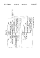
- plethysmogram detector 300 includes a lamp 301 which is provided opposite the center of a concavity into which the fingertip is inserted, and a light detector comprising a photoelectric element 302.
- Photoelectric element 302 is formed of resistors 303 to 306 and a bridge circuit. The output from this bridge circuit is amplified by differential amplifier 307. Further, the brightness of lamp 301 can be adjusted with a switch S so that the bridge circuit is balanced.
- the symbol V is the voltage of the electric source.
- the output of differential amplifier 307 is amplified further by amplifier 308.
- Waveform correcting circuit 309 modifies the amplified output to a rectangular waveform by clipping voltages which exceed a prefixed standard voltage.
- This output is differentiated at differentiating circuit 310, with micropulses generated in the negative direction by rectifier 311 to trigger one-shot multivibrator 312. As a result, a rectangular wave of duration T 0 is obtained in the output of one-shot multivibrator 312.
- the output of differential amplifier 307 passes through gate circuit 313 during an interval of the aforementioned duration T 0 .
- the output signal of gate circuit 313 passes through differentiating circuits 314, 315, with the output of the second derivative of the plethysmogram signal obtained in the output of differential circuit 315.
- Waveform correcting circuit 316 generates a sampling pulse for the output at each point in time where a valley b, peak c, and valley d appear.
- sampling circuit 317 samples the output from differential circuit 315, which has passed through delay circuit 318, and stores the result in successive recording circuit 319.
- Maximum value detection circuit 320 reads out the contents of successive recording circuit 319, and records the maximum value from among the amplitudes for valley b, peak c, and valley d. The output of maximum value detection circuit 320 is divided at voltage dividing circuit 321, with each divided voltage then output.
- Control circuit 322 successively outputs the voltages of valley b, peak c, and valley d, which are the output of successive recording circuit 319.
- This output is input into pulse height analyzer 323 which employs the output value of the voltage dividing circuit 321 as a comparison voltage, and, based on the voltages of valley b, peak c, and valley d, outputs values in which these voltages have been standardized (for example, ratios c/b, d/b, or ratios b/a, c/a, d/a, etc.) to output terminal OP.
- a microcomputer or similar device determines which waveform pattern from among the pre-typed acceleration plethysmogram waveforms the waveform output at output terminal OP is associated with, and displays this result.
- the measured plethysmogram is typed as one of the aforementioned patterns, based on the respective size relationship, and on the vertical relationship with respect to the base line of valley b, peak c, and valley d, to make a determination of the quality of circulation.
- the present invention was conceived in consideration of the aforementioned circumstances, and has as its first objective the provision of a device for accurately measuring conditions in a patient based on the circulation state and body movement.
- the present invention is characterized in the provision of a pulse wave measuring means which measures the user's pulse waves, and a body movement measuring means which measurers the movement of the user's body.
- the present invention composes a pulse wave measuring means for measuring the user's pulse waves, a body movement measuring means which measures the user's body movement, a calculating means which obtains an indicator showing the state of circulation in the user from the pulse waveform when the measured results of the body movement measuring means are below a prespecified value, and a notifying means which notifies the user of the aforementioned indicator.
- this embodiment composes a pulse wave measuring means for measuring the user's pulse waveforms, a pulse wave measurement directive detection means which detects a directive by the user to measure pulse waves, a calculating means which obtains an indicator showing the state of circulation in the user from the pulse waveform during the time that a plethysmogram measurement directive is being output, and a notifying means which notifies the user of the aforementioned indicator.
- the aforementioned calculating means obtains the acceleration plethysmogram pulse waveform, selects two peaks and valleys from among the plurality of peaks and valleys appearing in the acceleration plethysmogram, obtains an amplitude ratio for the selected peaks and valleys, and defines this ratio as the aforementioned indicator.
- notification of the state of circulation is provided to the user based on the measurement of his pulse waves. Accordingly it is possible for the user to know the state of his own circulation at all times, with the exception of during exercise. Thus, advanced notice of such diseases as ischemic heart disease or cerebrovascular disease can be obtained.
- the aforementioned indicator is defined as the value obtained by dividing the amplitude value of the second valley by the amplitude value of the first peak in the acceleration pulse waves.
- the amplitude value of the spectral component obtained from a spectral analysis of change across the time period of adjacent pulse waves is defined as the indicator.
- the ratio of the amplitudes of the low frequency and high frequency spectral components which are obtained from spectral analysis on changes over the time interval between adjacent pulse waves is defined as the indicator. Therefore, variation in the indicator which arises due to differences between individuals can be eliminated. Thus, in addition to managing the state of health, it is possible to provide objective data for determination.
- the number of times the amount of change in the time interval between adjacent pulse waves exceeds a prespecified time is set as the indicator.
- health state can be ascertained and managed based on a indicator which well expresses conditions of arousal or sedation in the body.
- the time interval between adjacent pulse waves is calculated, and the number of time in which the amount of change in continuous time intervals exceeds a prespecified time is defined as the indicator.
- the health management device has a pulse measurement means for measuring the pulse rate of the user.
- the notifying means notifies the user of the measured pulse rate.
- This health management device is provided with an evaluation means which measures an indicator when the measured result of the body movement measuring means is below a prespecified value, and measures the indicator again after the measured result of the body movement measuring means exceeds the prespecified value and then again returns below that prespecified value.
- the evaluation means then carries out an evaluation of the exercise performed by the user based on the difference in these indicators. Thereafter, the notifying means notifies the user of the results of this evaluation.
- the user is informed of his pulse rate while he is exercising.
- it is possible to adjust the amount of exercise appropriately, so that a more desirable training effect can be achieved.
- a pulse measuring means for measuring the user's pulse rate, and a pulse measurement directive detection means, for detecting a directive from the user to measure pulse rate are provided.
- the notifying means notifies the user of the pulse rate measurement result during the time that a pulse measurement directive is being output.
- an evaluation means which takes up the indicator obtained when the user issued a pulse measurement directive prior to the start of exercise, and the indicator obtained when the user issued a pulse measurement directive after the completion of exercise, and then carries out an evaluation of the exercise performed by the user based on the difference in these indicator values. Thereafter, the notifying means notifies the user of the results of this evaluation.
- the structure of the device can be simplified.
- Another embodiment is characterized in the provision of a body movement measuring means, which measures the user's body movement, and a body movement detection means, which detects that the measured result of body movement has exceeded a prespecified value.
- a body movement measuring means which measures the user's body movement
- a body movement detection means which detects that the measured result of body movement has exceeded a prespecified value.
- the notifying means provides a warning to the user when the body movement measurement exceeds a prespecified value during the time that the pulse wave measurement directive is being output.
- the user's movement during the measurement of the pulse waves is monitored, and a warning is provided when movement in excess of a prespecified value is detected. Therefore, the user is informed when his movement presents a hindrance to the accurate measurement of the pulse waves, and is prompted to carry out the measurement of the pulse wave again.
- the exercise to be performed by the user consists of a plurality of stages.
- This embodiment is characterized in the provision of a recording means in which indicator target values which are to be reached at each stage of exercise are prestored at each stage of exercise; and a comparing means which compares the indicator calculated by the calculating means and the target value corresponding to each exercise stage, at the point in time when the user completes each exercise stage.
- the notifying means notifies the user to proceed to the next stage of exercise.
- Another embodiment is characterized in the provision of a recording means which records indicators obtained at prespecified times and the moving average for indicators obtained over a past prespecified time interval; and a control means which reads out from the recording means past indicators which were obtained at the same clock time as the present time, calculates the moving average of the past indicator and the current indicator, stores this result in the recording means together with the current time, determines the difference between the moving average of the indicators obtained over a past prespecified time interval and the current indicator, and compares this difference to a prespecified value. If this difference exceeds the prespecified value, the notifying means provides a warning to the user.
- the user is provided with a warning when the difference between the current indicator and the moving average for indicators obtained over a prespecified period of time in the past exceeds a prespecified value, it is possible to provide the user with rapid notification in the case where his health state as observed from circulation has worsened compared to its usual state. Thus, the user is able to make active efforts to maintain his health by promptly consulting with a medical professional.
- Another embodiment is characterized in the provision of a device having a target setting means for setting the user's exercise target, a target correction means for correcting the target value based on the user's physical condition, and a first communications means; and a portable device having a notifying means for notifying the user, a measuring means for measuring the user's physical condition, and a second communicating means which can communicate in either direction with the first communications means.
- a device having a target setting means for setting the user's exercise target, a target correction means for correcting the target value based on the user's physical condition, and a first communications means; and a portable device having a notifying means for notifying the user, a measuring means for measuring the user's physical condition, and a second communicating means which can communicate in either direction with the first communications means.
- This embodiment is further characterized in that the target indicators and physical condition are sent and received by the first and second communications means.
- the user is notified of the exercise target values which have been set, and the target values are corrected as necessary based on the physical condition obtained from the user.
- the necessary information can be relayed between the two devices using the first and second communications means, processing which requires high speed calculations or large amounts of memory can be performed by a device which is provided external to the portable device.
- the portable device can have a simpler structure.
- the target value mentioned here is at least one from among exercising pulse rate, exercise duration per session, and frequency of exercise.
- this embodiment is also characterized in the provision of a pulse measuring means for measuring the user's pulse rate; and a guidance means which provides guidance to the user during the time that a pulse rate measurement directive is being received from the user, so that the pulse rate measured by the pulse measuring means is within prespecified limits which include the exercising pulse rate target value.
- the target setting means set the initial target value based on age and sex information provided by the user.
- the measuring means is provided with a pulse wave detection means which detects pulse wave in the user, with the measuring means then extracting the physical condition from these pulse waves.
- physical state is, for example, the amplitude value of the spectral component obtained from performing spectral analysis of change over the time interval between adjacent pulse wave.
- the ratio of the amplitude value of the low frequency spectral component and the amplitude value of the high frequency spectral component obtained from spectral analysis of change over the time interval between adjacent pulse waves may also be used.
- the physical state may also be equated to the number of times that the amount of change over the time interval between adjacent pulse waves exceeds a prespecified time.
- an acceleration pulse wave calculating means may also be provided for calculating the pulse wave's acceleration pulse wave.
- the physical state is the amplitude ratio between two peaks or valleys which are selected from among the plurality of peaks and valleys appearing in an acceleration pulse wave.
- the physical state prefferably be the amplitude ratio obtained when the amplitude value of the second valley is divided by the amplitude value of the first peak appearing in the acceleration pulse wave.
- an exercise quantity calculating means may be provided for calculating the amount of exercise performed by the user.
- the target correction means evaluates changes in the user's state due to exercise, based on the quantity of exercise and the amplitude ratio, and then corrects the exercise target values based on the results of this evaluation.
- the measurement means is provided with a sensor for measuring physical state.
- a first connection member for attaching the sensor to the portable device, and a second connection member for attaching the second communication means to the portable device are attached in a freely releasable manner to a connector which is provided to the portable device.
- connection members for respectively attaching the sensor and the second communication means to the portable device can be freely attached to and released from the connector which is provided to the portable device.
- the connector can be made compact, while the sensor and the second communication means can be used as necessary by connecting to the portable device.
- a means can be provided for newly setting the initial value of the exercise target value, based on the user's exercise capacity which is re-evaluated each time the user's performs exercise over a prespecified period of time.
- 601 is a pulse wave measuring means which is realized, for example, by the pulse wave sensor 4 and sensor interface 6 shown in FIG. 1.
- 602 is a body movement measuring means which is realized, for example, by acceleration sensor 5 and sensor interface 6.
- 603 is a calculating means which is realized by CPU1, for example.
- 604 is a recording means which is realized by RAM3, for example.
- 605 is a control means and 606 is an evaluation means, these being realized by CPU1, for example.
- 608 is a notifying means which is realized by display device 7 and display control circuit 8.
- 607 is a pulse wave measurement directive detection means which is realized by the operational portion 506 shown in FIG. 19, for example.
- FIG. 1 is a block diagram showing the structure of the health management device according to one embodiment of the present invention.
- FIG. 2(a) shows various arrangements of the acceleration plethysmogram of the fingertip plethysmogram.
- FIG. 2(b) shows the ranges for amplitude ratios d/a and c/a for each of the patterns in FIG. 2(b).
- FIGS. 3(a) and 3(b) show the same device incorporated in a wristwatch.
- FIG. 4 is a level view showing the structure of the wristwatch in greater detail, in the case where the device is incorporated in a wristwatch.
- FIGS. 5(a) and 5(b) show another arrangement for the case where the device is incorporated in a wristwatch.
- FIG. 6 shows the case where the device is incorporated in a necklace.
- FIG. 7 shows the case where the device is incorporated in a pair of eyeglasses.
- FIG. 8 is a view showing the relationship between the amount of exercise performed by the user and the rate of change in amplitude ratio d/a measured before and after exercise.
- FIG. 9 shows the relationship between an electrocardiogram and the RR interval.
- FIG. 10 shows the relationship between an electrocardiogram and the pulse wave.
- FIG. 11(a) shows the relationship between change in the RR interval and the frequency component which composes the change.
- FIG. 11(b) shows the results of spectral analysis of change in the RR interval.
- FIGS. 12(a) through 12(c) show the original waveform of a typical pulse wave, wherein FIG. 12(a) is a normal wave, FIG. 12(b) is a smooth wave, and FIG. 12(c) is a violent wave.
- FIG. 13 is a diagram for explaining the characteristics of the pulse waveform, over a single beat in the pulse wave.
- FIGS. 14(a) through 14(c) show the waveform of the fingertip plethysmogram, wherein FIG. 14(a) is the measured original waveform, FIG. 14(b) is the velocity plethysmogram, and FIG. 14(c) is the acceleration plethysmogram.
- FIG. 15 shows the extraction of a portion of the waveform of the acceleration plethysmogram in the fingertip plethysmogram.
- FIG. 16 is a block diagram showing the structure of a conventional acceleration plethysmograph.
- FIG. 17 shows the division of an acceleration plethysmogram waveform which is carried out when a measured acceleration plethysmogram is typed.
- FIG. 18 is a block diagram showing the structure of another conventional acceleration plethysmograph.
- FIG. 19 is a block diagram showing the structure of an exercise support device according to one embodiment of the present invention.
- FIG. 20 is a diagram showing the target value for the maximal oxygen uptake quantity.
- FIG. 21 is a diagram showing the required amount of exercise necessary to create a state of health.
- FIGS. 22(a) and 22(b) are diagrams showing how the maximal oxygen uptake quantity transitions together with duration of training, in the case where training is carried out at an exercise intensity corresponding to 50% of the maximal oxygen uptake quantity.
- FIG. 23 is a diagram showing the slight adjustment in the exercise target value in response to the user's physical condition.
- FIG. 24 is a diagram showing the mechanical connection between portable portion 70 and stationary portion 80 of the device.
- FIG. 25 is an upper view in which the wristwatch shown in FIG. 24 is enlarged.
- FIG. 26 is a perspective view of connector 500 on the wristwatch.
- FIGS. 27(a) and 27(b) are perspective views of connector piece 230 which attaches to the wristwatch.
- FIGS. 28(a) and 28(b) are perspective views of connector cover 260 which attaches to the wristwatch.
- FIGS. 29(a) and 29(b) are perspective views of connector cover 280 which attaches to the wristwatch
- FIGS. 30(a) and 30(b) are perspective views of connector piece 503 which attaches to the wristwatch.
- FIG. 31 is a view showing another embodiment for connecting portable portion 70 and stationary portion 80.
- FIG. 32 shows an example of the structure of the present invention.
- FIG. 2(a) shows acceleration pulse waveforms of a variety of types.
- a waveform is observed in which valley b falls significantly with respect to peak a, peak c rises to around the base line, and valley d falls only a small amount (see 1 or 2 in figure).
- valley b and valley d fall to about the same extent (see 3 in figure).
- the waveform may deform to one in which valley d falls below valley b (see 4 in figure), one in which peak c is positioned about on par with valley b (see 5 in figure), or one in which peak c is lower than valley b (see 6 in figure).
- an approach may be considered using the ratio of the amplitude of peak a and the amplitude of another peak or a valley.
- a value for d/a of within 10% indicates pattern (1); 10-35% indicates pattern (2); 35-60% indicates pattern (3); and 60-100% indicates patterns (4) through (6).
- amplitude ratio c/a when the ratio of the amplitude of peak c to the amplitude of peak a, i.e. amplitude ratio c/a, is employed as the standard, then a value for c/a of within -10% indicates pattern (1); 10-15% indicates pattern (2); within -15% indicates pattern (3); 0-20% indicates pattern (4); 20-40% indicates pattern (5); and above 40% indicates pattern (6). Since, the range for patterns (2) through (4) overlap, this approach may be used to categorize patterns (4) through (6) only, or may be used in combination with the value of the amplitude ratio d/a.
- the amplitude ratio may be a negative value, indicating that peak c or valley d are located above the base line.
- the more closely the waveform of his acceleration pulse wave resembles the pattern (1) type waveform the better the user's state of health.
- the more closely the waveform of his acceleration pulse wave resembles a pattern (6) type waveform the worse the state of his health tends to be.
- this may be considered useful for predicting the occurrence of ischemic heart disease (myocardial infarction, angina pectoris) or cerebrovascular disease (cerebral apoplexy, arachnoideal bleeding).
- maximal oxygen uptake quantity can serve as a measure of the state of health, and serves an important function in setting the level of intensity in exercise.
- Maximal oxygen uptake quantity which is defined as the maximum amount of oxygen which can be taken in one minute, can serve as an absolute index for evaluating an individual's exercise capacity.
- the value for the maximal oxygen uptake quantity is typically employed after converting to a per kilogram body weight value.
- this target value is determined based on sex and age, as shown in FIG. 20, for example (source: Research Related to Application Methods for Required Amount of Exercise and Measurement of Effects Thereof and Research Related to the Use of Exercise Duration, Intensity and Frequency to Create a State of Health, 1989, 1991, and 1992 subsidies for Public Welfare and Science Research No. 00209065, No. 00264886, No. 00464607; and Industry Committee to Research Development of Physical Health).
- Aerobic exercise which generates energy as oxygen is taken in through respiration during exercise is suitable for safely reaching and maintaining this maintenance target value.
- To maintain aerobic exercise it is necessary to maintain exercise intensity below 70% of the maximal oxygen uptake quantity.
- this level of exercise is not hard and leaves the user psychological leeway while exercising.
- this level is more appropriate to activation of fat metabolism as compared to more intense exercise.
- an oxygen shortage to the heart is not likely to occur, so that this level of exercise is highly safe and free from the concern that blood pressure will rise to an extent which is dangerous.
- fourth, at this level of exercise there is almost no pain in the leg muscles and joints, and little generation of lactic acid, a metabolite of muscle fatigue, so that exercise can be continued for a long period of time.
- the targeted amount of exercise i.e., the desired amount of exercise needed to create a state of health
- FIG. 21 shows the total number of minutes of exercise to be carried out in one week and the targeted heart rate.
- the maximal oxygen uptake quantity reaches the targeted value of 37 ml/kg/min (male) or 31 ml/kg/min (female) for a person in their sixties (see FIG. 20).
- the achievable level of the maximal oxygen uptake quantity is directly proportional to the number of minutes of exercise per week.
- each exercise session in order for the body to respond to aerobic exercise, it is necessary to continue exercising for at least 10 minutes or more. Also, it is preferable to exercise a total of 20 minutes or more per day, and three or more times per week (but preferably every day).
- FIGS. 22(a)-22(c) show the transition in exercise intensity from training carried out under the standards described above (source: same as above).
- FIG. 22(a) shows the change in % Vo 2max /wt, where the training period is plotted on the horizontal axis and the % Vo 2max /wt value is plotted on the vertical axis.
- % Vo 2max is the maximal oxygen uptake quantity
- % Vo 2max is the proportion of the oxygen uptake quantity at each point in time with respect to the maximal oxygen uptake quantity.
- % Vo 2max /wt is the value obtained when % Vo 2max is converted to a per kilogram body weight value.
- FIG. 22(b) shows the change over time in the maximal oxygen uptake quantity per unit body weight VO 2max /wt and training intensity as a result of training.
- the training period is plotted on the horizontal axis and the absolute exercise intensity is plotted on the vertical axis.
- the units for the vertical axis are mets (metabolic equivalents), which can be employed as a unit for absolute evaluation of energy metabolism.
- the patients were male, and exercise of an intensity corresponding to 50% of the maximal oxygen uptake quantity was carried out for 180 minutes per week.
- the present invention consists of a continuous cycle of:
- the required amount of exercise as described above is a standard value based on an average person. In reality, the amount of exercise required for a given individual will vary depending on age, sex, degree of health, and other physiological conditions.
- the present invention makes it possible to prescribe an exercise plan which takes into consideration individual differences and conditions by evaluating a person's state of health using physiological conditions obtained from the acceleration pulse wave and the like, and then adjusting the target value for exercise based on the results of this evaluation, so that the user is guided to perform exercise which is suitable to creating a state of health.
- FIGS. 22(a)-22(c) show as an example, as a general rule training is carried out for 10 weeks without receiving any guidance from a doctor or coach, so that exercise is carried out in accordance with the fixed target value indicated for that period.
- fine adjustments are made in the time, intensity and frequency target values after taking into consideration the patient's or athlete's physical condition. Accordingly, from the short term perspective, every 10 weeks, for example, the device of the present invention carries out a continuous cycle of:
- the target value will change as shown in FIG. 23 in response to the quality of the individual's physical condition. This is also true for the case of exercise intensity and exercise frequency. Moreover, this fine adjustment is of course carried out weekly and daily, but may also be carried out any number of times when training is performed in a single day, for example, at each 15 or 20 minute training session, to finely adjust the next exercise target.
- FIG. 1 is a block diagram showing the structure of this device.
- CPU1 central processing unit
- CPU1 central processing unit
- the function of CPU1 will be explained below under the section covering operation.
- ROM2 read-only memory
- ROM2 also stores the target value for exercise duration, the values of the upper and lower limits for exercise intensity, and the target value for exercise intensity (average exercise intensity), for realizing desirable exercise corresponding to the pattern of the user's health state, i.e., amplitude ratio d/a, etc.
- Random access memory RAM3 is employed as an operational area when CPU1 is carrying out operations (for example, the area for storing the total exercise amount while the user is exercising). In addition, RAM3 also stores the measured values and operational results from a variety of sensors which will be explained below.
- Pulse wave sensor 4 is an optical pulse wave detection sensor which is attached to the user's first finger, for example.
- This pulse wave sensor 4 is composed of a light emitting diode and a light sensor employing a phototransistor or the like, for example. Light radiated from the light emitting diode is received by the light sensor after being reflected via the blood vessels under the skin, and undergoes photoelectric conversion, to obtain a pulse wave pulse wave detection signal as a result. Where consideration is given to the signal noise ratio, it is acceptable to employ a diode which emits blue light.
- Acceleration sensor 5 is a body movement sensor which senses movement of the user's body. It may be attached to the same location, for example the finger, as pulse wave sensor 4.
- Sensor interface 6 uptakes the output of pulse wave sensor 4 and acceleration sensor 5 at specified intervals, converts the analog signal taken up into a digital signal and outputs it.
- Display device 7 displays a variety of information such as messages and the like to the user and may, for example, be a liquid crystal display provided to a wristwatch.
- Display control circuit 8 receives display information from CPU1, converts the display information to the format employed by display device 7, and carries out the display of the information on display device 7.
- watch circuit 9 In addition to having the ordinary functions associated with a watch, watch circuit 9 also sends out an interrupt signal to CPU1 at clock times which have been preset by CPU1, or after the elapse of a time period which has been preset by CPU1.
- a number of arrangements may be considered as a method for attaching a health management device to the body as a portable device.
- a health management device to the body as a portable device.
- One example of these is described below, however, other arrangements with a variety of other portable devices are of course possible.
- an embodiment may be proposed in which the health management device is incorporated into a wristwatch such as shown in FIGS. 3(a) and 3(b).
- the health management device of this embodiment is formed of a device main body 100 having a wristwatch structure, a cable 101 connected to device main body 100, and a sensor unit 102 provide to the end of cable 101.
- a wristband 103 is attached to device main body 100 which wraps around the user's wrist from the 12 o'clock position and affixes at the 6 o'clock position of the wristwatch.
- Device main body 100 can be freely attached and removed from the user's wrist by means of this wristband 103.
- Sensor unit 102 is blocked from light by band 104 employed for fixing the sensor in place, and is attached between the base and second joint of the user's index finger.
- band 104 employed for fixing the sensor in place
- cable 101 can not only be made shorter, but will not present an interference to the user during exercise.
- sensor unit 102 it is known that when the temperature distribution from the palm to the tip of the finger is measured, the temperature at the tip of the finger drops markedly in the case where the temperature of the surrounding environment is low, whereas the temperature at the base of the finger falls comparatively little. Accordingly, if sensor unit 102 is attached to the base of the finger, it is possible to accurately measure pulse rate and the like, even in the case where exercising outdoors during cold weather.
- a connector 105 is provided at the 6 o'clock position on the face of the wristwatch.
- a connector piece 106 which is provided to the end of cable 101, is releasably attached to connector 105. By releasing connector piece 106 from connector 105, the device may be used as an ordinary wristwatch or stopwatch. Also, in order to protect connector 105, a specific connector cover is attached when cable 101 and sensor unit 102 are released from connector 105. With the exception of an electrode component, this connector cover may be formed of parts formed in the same way as connector piece 106.
- connector 105 is disposed toward the user, facilitating its manipulation.
- connector 105 does not extend out from device main body 100 in the 3 o'clock position, the user can freely move his wrist during exercise. Thus, even if the user falls during exercise, the back of the hand will not impact connector 105.
- FIG. 3 The other parts shown in FIG. 3 will now be explained in greater detail with reference given to FIG. 4.
- FIG. 4 shows the device main body 100 of this embodiment in detail, with cable 101 and wristband 103 detached.
- parts which are equivalent to those shown in FIGS. 3(a) and 3(b) have been assigned the same numeric symbol and an explanation thereof has been omitted.
- device main body 100 is provided with a watch case 107 made of a resin.
- a liquid crystal display 108 is provided to the face of watch case 107 which displays in digital form the current time and date, as well as pulse information such as pulse rate and the like.
- LCD device 108 is comprised of first, second, and third segment display regions 108-1, 108-2, and 108-3, respectively, and a dot display region 108-D.
- First segment display region 108-1 is positioned at the upper left area of the display panel;
- second segment display region 108-2 is positioned at the upper right area of the display panel;
- third segment display region 108-3 is positioned at the lower right area of the display panel; and dot display region 108-D is positioned at the lower left area of the display panel.
- the date, day of the week and current time are displayed in first segment region 108-1, while the passage of time when carrying out various time measurements is displayed in second segment region 108-2.
- Pulse rate and the like measured during the measurement of pulse wave pulse waves are displayed in third segment region 108-3.
- various information can be graphically displayed in dot display region 108-D, in addition to a variety of other displays such as a mode display, which indicates which mode the device is in at a particular time, the pulse waveform's original waveform/velocity pulse waveform/acceleration pulse waveform display, a bar graph display which shows change in the pulse rate over time, and the like.
- mode refers to a variety of modes such as a mode for using the device as a health management device, a mode for setting the time and date, a mode for using the device as a stop watch, and the like.
- a controller 109 for carrying out signal processing for displaying changes in pulse rate or the like on LCD device 108 is housed inside watch case 107.
- Controller 109 includes a watch circuit for carrying out watch functions.
- an ordinary clock time display may be used for LCD device 108, however, live time or split time displays for use when the device is operated as a stop watch are also possible.
- Button switches 111-117 are provided to the outer periphery and surface of watch case 107.
- button switch 111 which is at the 2 o'clock position on the wristwatch, is pressed, an alarm is set to sound one hour thereafter.
- Button switch 112 which is at the 4 o'clock position on the wristwatch, is provided for directing switching of the various modes the device has when functioning as an ordinary wristwatch.
- Button switch 114 which is at the 8 o'clock position on the wristwatch, switches between the various graphic displays which are to be displayed on dot display region 108-D.
- button switch 115 which is at the 7 o'clock position on the wristwatch, the form of time and date display (i.e., time displayed in seconds/minutes/hours, 12 or 24 hour display, etc.) can be switched in the day and date correction mode.
- Button switch 116 which is positioned below LCD display 108, can be used when correcting time or date, by decreasing the setting by one. Additionally, when timing a lap, button switch 116 can be used as a switch for informing CPU1 of the completion each lap.
- Button switch 117 which is positioned above LCD 108, is employed for indicating the initiation or termination of operation of the health management device. In addition to being used to increase the time and date setting by one, button switch 117 can also be used to indicate the initiation or termination of a variety of time elapse measurements.
- a button-shaped battery 118 is housed in watch case 107 and serves as an power source for the device.
- Cable 101 shown in FIG. 3 supplies electric power from battery 118 to sensor unit 102, and sends the detection results from sensor unit 102 to controller 109.
- a horizontally long watch case 107 is employed which is longer in the horizontal, (i.e., 3 o'clock to 9 o'clock) direction, than in the vertical (i.e., 6 o'clock to 12 o'clock) direction.
- wrist band 103 is connected to a watch case 107 at a position shifted toward the 3 o'clock side of the watch.
- a large overhang 119 is present on the 9 o'clock side the wristwatch, but is absent from the 3 o'clock side of the watch. Accordingly, the user can bend his wrist when using or carrying the horizontally long watch case 107. Further, even if the user falls, he will not hit the watch case with the back of his hand.
- a flat piezo element 120 used as a buzzer is disposed inside the watch case 107, at the 9 o'clock position with respect to the battery 118.
- Battery 118 is heavier than piezo element 120, such that the position of the weight center of device main body 100 shifts toward the 3 o'clock side.
- wrist band 103 is connected to the side of the main body 100 toward which the weight center has shifted.
- device main body 100 can be attached to the arm in a stable manner.
- battery 118 and piezo element 120 are disposed in the planar direction, device main body 100 may be made thinner. By providing a battery cover to the rear surface of the wristwatch, the user can easily change the battery.
- the correspondence between the parts in FIG. 1 and those in FIGS. 3(a), 3(b) and 4 is as follows.
- the controller 109 in FIG. 4 is equivalent to CPU1, ROM2, RAM3, sensor interface 6, display control circuit 8 and watch circuit 9 in FIG. 1.
- sensor unit 102 in FIGS. 3(a), 3(b) is equivalent to pulse wave sensor 4 and acceleration sensor 5 in FIG. 1, while the liquid crystal display 108 in FIGS. 3 and 4 is equivalent to display device 7 in FIG. 1.
- the user presses button switch 117 to activate the functioning of the device.
- the pulse waveform and the acceleration value are then sent to the sensor interface 6 from pulse wave sensor 4 and acceleration sensor 5, respectively, and converted to a digital signal.
- CPU1 sends the pulse wave pulse waveform taken up to display control circuit 8, after which the pulse waveform is displayed on display device 7.
- the user can observe as a graphic display the pulse wave pulse waveform, which is changing over time, on the dot display area of 108-D of the liquid crystal display 108 shown in FIG. 4, for example.
- CPU1 is designed to measure the resting pulse rate just once prior to the start of exercise after the user has pressed button switch 117. In this case, CPU1 determines whether or not the user is moving (i.e., whether or not the user is in a state or repose) according to whether or not the movement of pulse wave sensor 4 accompanying movement of the user is to an extent which will impair detection of the pulse wave. In other words, if the output value of acceleration sensor 5 exceeds a prespecified value (0.1 G, for example), then CPU1 determines that the user is moving (i.e., not in a state of repose). Since detection of the pulse wave cannot be accurately carried out in this case, CPU1 displays a message on display device 7 alerting the user not to move.
- a prespecified value 0.1 G, for example
- CPU1 determines that the user is not moving (i.e., is in a state of repose).
- the pulse waveforms are then taken up for a prespecified period of time only from sensor interface 6, and stored in RAM3.
- the pulse waveforms taken up during this time period are then separated into wavelength units, and the number of wavelengths is counted. This is then converted to a per minute value to calculate the pulse rate.
- the thus calculated pulse rate is then stored in RAM3 as the resting pulse rate.
- CPU1 reads out a single wavelength segment from the pulse waveform stored in RAM3, and then differentiates this waveform twice with respect to time, to obtain an acceleration pulse waveform such as shown in FIG. 15.
- CPU1 determines peak a, valley b, peak c and valley d by obtaining the inflection points of the acceleration pulse waveform. The value of the amplitude at each of these inflection points is then obtained.
- These inflection points can be obtained by the typical methods, such as by taking the time derivative of the acceleration pulse wave.
- the calculated acceleration pulse waveform, and the velocity pulse waveform which was obtained in the process of obtaining the acceleration pulse waveform may be graphically displayed on display device 7.
- CPU1 calculates values in which each of the amplitude values of valley b, peak c and valley d are normalized by the amplitude value of peak a, i.e., the amplitude ratios b/a, c/a, and d/a, and stores the calculated results in RAM3. From among these, amplitude ratio d/a is most useful as an indicator which expresses the state of circulation. Therefore, as a general rule, the explanation of the embodiments of the present invention which follows hereinafter will employ just amplitude ratio d/a. Further, while strictly speaking, it is preferable to employ both amplitude ratios d/a and c/a, the following discussion of determination will employ only amplitude ratio d/a as the most convenient method.
- CPU1 guides the user as to what degree of exercise should be performed.
- CPU1 determines which pattern (1) through (6) is associated with the user's acceleration pulse waveform prior to exercise, based on the amplitude ratio d/a obtained as above and the table shown in FIG. 2(b).
- the pattern type is stored in RAM3 as the pattern of the user's acceleration pulse waveform prior to exercise, and is displayed on display device 7.
- the pulse waveform is found to be a pattern (3) type waveform, then a supplementary message such as "health state beginning to deteriorate" is displayed on display device 7.
- the exercise intensity target value, the upper and lower limit values for exercise intensity, and the exercise duration target value corresponding to the obtained pulse wave pattern are read out from ROM2 and stored in RAM3, and displayed on display device 7 as target values for the user during exercise.
- CPU1 When the user starts to exercise, the output value from acceleration sensor 5 gradually increases as the movement of the body becomes more rigorous. When the output value of the acceleration sensor exceeds the aforementioned prespecified value at some point in time onward, CPU1 recognizes that the user has begun to exercise. CPU1 then reads out the clock time from watch circuit 9 and stores this as the exercise-start time in RAM3. At the same time, CPU1 sets watch circuit 9 to generate an interrupt signal when the targeted time for exercise duration has elapsed. Also, in order to calculate the total amount of exercise during the exercise session, CPU1 initializes the memory area provided in RAM3 at 0!.
- CPU1 then measures the user's pulse rate and exercise amount, and provides guidance as the user is exercising.
- CPU1 first reads out the pulse waveform from sensor interface 6 at prespecified time intervals, and calculates the user's pulse rate. This pulse rate is converted to display information, sent to display control circuit 8, and then displayed on display device 7.
- CPU1 calculates the amount of exercise, which, in this case, is displayed in the form of calories. Since calories burned are approximated as the product of pulse rate and exercise duration, CPU1 multiplies the pulse rate obtained as described above by the time which has elapsed from the immediately preceding pulse rate measurement to the current pulse rate measurement. When calculating the exercise amount, it is typically the case that the immediately preceding pulse rate will differ from the current pulse rate. Therefore, it is acceptable to employ the average of the two values. CPU1 obtains the total exercise amount by adding the current exercise quantity to the total amount of exercise calculated through the immediately preceding pulse rate measurement. The total exercise amount since the beginning of the exercise session, and the exercise amount from the previous pulse rate measurement through the current pulse rate measurement, are stored in RAM3, and displayed on display device 7.
- the amount of exercise may be obtained as the product of exercise intensity and exercise duration. Accordingly, it is also acceptable to display the exercise amount obtained as this product in place of the calorie display.
- the measured pulse rate and the exercise intensity satisfy the following well-known Karvonen equation, so that exercise intensity can be calculated from the resting pulse rate which was prestored in RAM3 and the pulse rate which is measured during exercise, to obtain the amount of exercise.
- CPU1 checks whether or not the exercise intensity calculated from the measured pulse rate using formula (1) is outside the range determined by the aforementioned upper and lower limit values for exercise intensity. If exercise intensity exceeds the upper limit value, then CPU1 guides the user to exercise a bit more moderately, while if exercise intensity falls below the lower limit, CPU1 guides the user to slightly increase the intensity of exercise.
- the user can increase or decrease the exercise being performed.
- excessive or ineffective exercise is avoided. In this way, monitoring is carried out to ensure that exercise of the appropriate intensity is performed.
- CPU1 When an interrupt from watch circuit 9 is generated after the elapse of the targeted exercise duration, CPU1 outputs a directive to the user to stop exercising. The user either stops immediately, or continues until reaching a more convenient stopping point. Accordingly, the output value of acceleration sensor 5 gradually decreases. Meanwhile, since CPU1 is monitoring the output value of acceleration sensor 5, it detects that the output value has again fallen below the prespecified value described above, and thereby recognizes that the user has suspended exercise.
- CPU1 calculates the amplitude ratio d/a following the same procedure as performed prior to starting exercise, and reads out the current clock time from watch circuit 9, which it records in RAM3 as the exercise-stop time.
- CPU1 then calculates the total exercise duration based on the exercise-start time and the exercise-stop time, and stores this in RAM3 in the same manner.
- CPU1 displays the pre-exercise amplitude ratio d/a, the post-exercise amplitude ratio d/a, the total exercise amount, and the total exercise duration on display device 7 in accordance with the manipulation of a button switch by the user.
- CPU1 obtains the target exercise amount from the exercise intensity target value and the exercise duration target value, and determines whether or not the total exercise amount measured is within a prespecified range centered around this target value. If the exercise amount is not correct, then CPU1 notifies the user of this fact, together with the targeted value for the exercise amount, so that the user is made aware that exercise was not carried out as directed.
- CPU1 also carries out the same processing with respect to exercise duration, and alerts the user when a notable difference is found between the targeted value and the actual measured value.
- CPU1 determines which of the patterns shown in FIG. 2(b) is associated with the amplitude ratio d/a measured after exercise, and displays the post-exercise pattern type on display device 7. If a comparison of the pre-exercise and post-exercise patterns reveals that there was an improvement toward a type (1) pattern, then a message such as "health state improved" is displayed on display device 7. On the other hand, a comparison may reveal a deterioration toward a type (6) pattern. Since further exercise may not be desirable in this case, the user is cautioned not to exercise, and to consult a physician if necessary.
- this post-exercise exercise pattern i.e., amplitude ratio d/a
- amplitude ratio d/a is set as the pre-exercise pattern (amplitude ratio d/a) for the exercise which is to be performed from that point on.
- a new target value is set from this pattern (amplitude ratio d/a), and exercise guidance is continued.
- CPU1 determines that exercise has ended, and terminates further exercise guidance.
- the user's health state is moved toward a better condition by providing guidance to the user to carry out appropriate exercise.
- the following may be considered as one method for evaluating the exercise performed by the user.
- FIG. 8 shows an example of the relationship between the amount of exercise performed by the user and the rate of change in amplitude ratio d/a before and after exercise.
- the rate of change in amplitude ratio d/a is small, with a value of +5% or less generally obtained (region I in FIG. 8).
- the rate of change in amplitude ratio d/a gradually increases above +5%.
- the rate of change begins to fall after a certain point, until it again is around +5% (region II in FIG. 8).
- the rate of change in amplitude ratio d/a falls further, dropping below +5% to around -10% (region III in FIG. 8).
- a further increase in the amount of exercise leads to a further decline in the rate of change in amplitude ratio d/a, to below -10% (region IV in FIG. 8).
- CPU1 carries out an evaluation of exercise based on the relationship between the amount of exercise and the rate of change in amplitude ratio d/a. In order to do this, CPU1 determines the difference between the post-exercise amplitude ratio d/a and the pre-exercise amplitude ratio d/a and divides this difference by the pre-exercise amplitude ratio d/a, thereby calculating the rate of change in amplitude ratio d/a. The rate of change in the obtained amplitude ratio d/a and the measured amount of exercise are plotted on the graph in FIG. 8, and CPU1 then makes an evaluation of the exercise performed by the user according to which region I-IV this plot is positioned in.
- the preceding embodiment described a case employing the amplitude ratio d/a only.
- an evaluation method which uses both amplitude ratio d/a and c/a, it is possible to carry out an evaluation of exercise which is even more accurate. Namely, if, for example, the value of the amplitude ratio is 20%, then a determination can be made that the waveform of the acceleration pulse wave is associated with a pattern (2) type waveform.
- the value of amplitude ratio d/a is 80%, then it is possible to specify that the acceleration pulse waveform is associated with one of patterns 4 through 6. Reference is then made to the value of the amplitude ratio c/a to determine which is the pattern from among these. If the value of amplitude ratio c/a is 30%, for example, then, from FIG. 2(b) it is possible to determine that the acceleration pulse waveform is associated with a pattern (5) type waveform.
- Calorie consumption may be cited as one example.
- CPU1 sets the targeted value for calorie consumption prior to beginning exercise, and calculates calorie consumption each time the pulse rate is measured during exercise.
- CPU1 calculates the total calorie consumption from the start of exercise and stores this value in RAM3. When this value exceeds the set target value, CPU1 provides notification to the user.
- Information such as the power spectrum obtained from heartbeat variation has begun to be used in the diagnosis and treatment of various ailments such as heart disease, central nerve disorders, peripheral nerve disorders, diabetes, high blood pressure, cerebrovascular disease, sudden death and the like in recent years. Accordingly, this embodiment obtains the LF (low frequency), HF (high frequency) and RR50 indicators from an analysis of the pulse tidal wave, which corresponds to the tidal wave in heartbeat variation, and employs these as indicators of the user's physical state. We will first explain the significance of these indicators.
- the interval between the R wave of one heart beat and the R wave of the next heart beat is referred to as the RR interval.
- This RR interval is a numerical value which serves as an indicator of the functioning of the autonomic nervous system in the human body.
- FIG. 9 shows heartbeat and the RR interval obtained from the waveform of this heartbeat in an electrocardiogram. As may be understood from this figure, an analysis of the measured results in an electrocardiogram reveals that the RR interval varies over time.
- variation in blood pressure measured at the radius artery or the like is defined as the variation in blood pressure at each beat from contraction to relaxation of the heart, and corresponds to variation in the RR interval in an electrocardiogram.
- FIG. 10 shows the relationship between the electrocardiogram and blood pressure.
- the blood pressure during each contraction and relaxation in a heart beat can be measured as the maximum value of arterial pressure, and the minimum value immediately preceding this maximum value in each RR interval.
- the variations are composed of waves having a plurality of frequencies. These may be classified into the following three types of variation components.
- FIG. 11(a) shows the waveform of variation in the RR interval of a measured pulse wave and the waveform of each of the components of variation in the case where the waveform of variation is segregated into the three frequency components noted above.
- FIG. 11(b) shows the results of spectral analysis on the waveform of variation in the RR interval shown in FIG. 11(a).
- peaks are apparent at two frequencies near 0.07 Hz and 0.25 Hz.
- the former frequency value is the LF component, while the latter is the HF component.
- the trend component cannot be read in the figure because it is below the limit for measurement.
- the LF component is related to the activity of the sympathetic nervous system. The larger this component, the greater the increase in tension.
- the HF component is related to the activity of the parasympathetic nervous system. The larger the amplitude of this component, the more relaxed the state.
- LF/HF which is the ratio of the amplitudes of the LF and HF components
- RR50 is defined by the fixed number at which the absolute value of the pulse wave interval corresponding to the RR interval for two consecutive heart beats varies by 50 milliseconds or more, when measurements of pulse wave are carried out over a prespecified period of time. The larger the value of RR50, the more sedate the subject is, while the smaller the value of RR50, the more aroused the subject is.
- the HF component or the LF/HF value increase or decrease from a value indicating a state of tension to a value indicating a state of relaxation. Accordingly, it may be hypothesized that by observing not only the HF component and LF/HF value, but also the LF component and the RR55 value, it is possible to judge whether or not the body state is good by observing the increase and decrease in the values in each of the indicators. Accordingly, these indicators may be used in place of amplitude value d/a.
- the acceleration pulse waveform was divided into 6 patterns in the preceding embodiment.
- the indicators are divided into a number of grades according to the value thereof.
- An exercise intensity target value, upper and lower limit values for exercise intensity, and a target value for exercise duration have been preset in ROM2 corresponding to each of these grades.
- CPU1 checks the output value of acceleration sensor 5 and, after confirming whether or not the user is in a state of repose, measures the resting pulse rate once, and stores this value in RAM3. Next, CPU1 takes up the pulse waveform, and calculates the four indicators based on this pulse waveform. The processing which follows thereafter will now be explained in detail below.
- CPU1 calculates the time derivative of the pulse waveform, and obtains all the clock times at which there is pole in the waveform by determining the where the time derivative is zero.
- CPU1 determines whether each pole is a maximum or minimum, from the slope of the waveform in the vicinity the pole (i.e., the time derivative). In other words, for a given pole, CPU1 calculates the moving average of the slope of the waveform over a fixed time interval preceding the pole. If this moving average is positive, then the pole is a maximum, while if the value is negative, the pole is a minimum.
- CPU1 determines the minimum point present immediately preceding the maximum point.
- the pulse wave amplitudes at the maximum and minimum points are read out from RAM3, and the difference between them is determined. If this difference exceeds a prespecified value, then the clock time of that maximum point is designated as a peak in the pulse wave. After carrying out this peak detection processing on all the pulse waveforms taken up, the time interval between two adjacent pulse wave peaks is calculated based on the clock time at which these peaks occur (corresponding to the RR interval between heartbeats).
- the value of the obtained RR interval is discrete along the time axis. Accordingly, a curved line such as shown in FIG. 11(a) is obtained by interpolation between neighboring RR intervals using a suitable interpolation method. Next, a spectrum such as shown in FIG. 11(b) is obtained by carrying out FFT processing on the interpolated curved line. Processing to determine maximums is carried out in the same manner as performed on the pulse waveform, to obtain the frequencies in the spectrum corresponding to the aforementioned maximum and maximum values.
- the maximum value obtained in the low frequency region is defined as the LF component
- the maximum value obtained in the high frequency region is defined as the HF component.
- the amplitudes of these components are obtained and the amplitude ratio LF/HF is calculated.
- the time difference in neighboring RR intervals is sequentially obtained based on the RR interval obtained above. Next, a check is made of each of these time differences to confirm whether or not the time difference exceeds 50 milliseconds, and the fixed number of time differences exceeding 50 milliseconds is counted and set as RR50.
- CPU1 directs the user regarding the exercise to be carried out. First, CPU1 determines the grade to which the index value obtained as above is associated. The determined grade and the value of the index are stored in RAM3, and displayed on display device 7. The exercise intensity target value, the upper and lower limit values for exercise intensity, and the target value for exercise duration are read out from ROM2, stored in RAM3 and displayed on display device 7, so that the user is presented with these exercise target values.
- CPU1 recognizes this, and stores this as the exercise-start time in RAM3, and sets the targeted exercise duration in watch circuit 9. Then, in the same manner as in Embodiment 1, CPU1 measures the user's pulse rate and exercise amount during exercise, and provides guidance to the user as he exercises. In other words, CPU1 calculates the user's pulse rate and the amount of exercise from the previous pulse rate measurement to the current pulse rate measurement, thereby determining the total amount of exercise since the user started to exercise. These values are stored in RAM3, and displayed on display device 7. CPU1 checks whether or not the exercise intensity calculated from equation (1) is within the range determined by the upper and lower limit values for exercise intensity, and outputs directive relating to the appropriate exercise intensity to the user.
- CPU1 directs the user to end exercise when an interrupt from watch circuit 9 is generated after the targeted exercise duration has elapsed.
- CPU1 observes the output of acceleration sensor 5 and waits for the user to actually stop exercising.
- CPU1 calculates each indicator in the same way as prior to the start of exercise, and reads out the exercise-stop time from watch circuit 9 to calculate the total exercise duration.
- CPU1 then stores all these values in RAM3, and displays them on display device 7.
- CPU1 determines whether the total amount and duration of the exercise just performed are within the prespecified limits based on the respective target values. When exercise has not been carried out as directed, then CPU1 notifies the user of this fact.
- CPU1 determines the grade to which the index value after exercise is associated, and displays the obtained grade and index value on display device 7.
- CPU1 compares the index values before and after exercise. If an improvement in physical state is observed, then a message to that effect is displayed on display device 7, while if a deterioration in physical state is observed, then a warning is provided to stop exercise and consult a physician.
- the grade obtained after exercise is set as the pre-exercise grade for the exercise to performed from that point on.
- a new target value is obtained based on this grade, and CPU1 continues exercise guidance.
- Embodiment 1 Part of the health management device described in Embodiment 1 is modified in this embodiment. Namely, in the Embodiment 1, the device (or more specifically, CPU1) automatically determined whether or not the user was in a state of repose based on the measured result from acceleration sensor 5. In contrast, in this embodiment, the user himself determines whether or not he is in a state of repose, and provides direction of this fact to the device.
- the device or more specifically, CPU1
- the device automatically determined whether or not the user was in a state of repose based on the measured result from acceleration sensor 5.
- the user himself determines whether or not he is in a state of repose, and provides direction of this fact to the device.
- the operational mode in the first embodiment was composed of two modes, namely, one mode in which the device functions as a health management device, and another mode in which the device is used as a stop watch or an ordinary watch in which time and date is set.
- the operational mode is divided into three types of modes.
- the device In the first mode, the device has no function as a health management device, but serves as an ordinary wristwatch when incorporated in a timepiece. In the remaining two modes, the device functions as a health management device. Namely, the second mode is a pulse wave measurement mode which carries out measurement and analysis of the user's pulse waves before or after exercise, based on the assumption that the user is in a state of repose. The third mode is a pulse measurement mode for measuring the pulse rate while the user is exercising, and providing exercise guidance.
- button switch 117 The user carries out switching between these three modes using button switch 117.
- button switch 117 was a switch for starting or terminating the operation of the device as a health management device.
- button switch 117 serves as a button switch for cyclic switching between the three modes described above. Namely, each time button switch 117 is pressed, the device cycles from mode 1 through mode 3 (mode 1 ⁇ mode 2 ⁇ mode 3 ⁇ mode 1). Further, the device is designed not to fix the mode while mode switching is being carried out. Rather, the user continues pressing button switch 117 until the desired mode appears.
- the user himself makes the determination that he is in a state of repose, whereas in the first embodiment the determination was made using acceleration sensor 5. Accordingly, in this embodiment, an acceleration sensor 5 is not needed.
- CPU1 reads out a portion of the pulse waveform, determines the acceleration pulse waveform, sets peak a, valley b, peak c and valley d, calculates amplitude ratio d/a, and determines the acceleration pulse waveform pattern from this amplitude ratio d/a.
- CPU1 then stores these values in RAM3.
- CPU1 reads out the exercise target values corresponding to this pattern from ROM2, stores them in RAM3, and displays these values on display device 7, along with a message stating that pre-exercise pulse wave measurement is completed.
- CPU1 directs the user to end exercise when an interrupt from watch circuit 9 is generated.
- exercise is terminated in accordance with this directive, the user again switches the device to pulse wave measurement mode by manipulating button switch 117.
- CPU1 reads out the exercise-stop time, calculates the total exercise duration, and stores this in RAM3.
- CPU1 recognizes that the current pulse wave measurement mode is for measuring the post-exercise pulse wave. Then, following the same procedure employed prior to the start of exercise, CPU1 calculates the amplitude ratio d/a from the pulse waveforms taken up, determines the acceleration pulse wave pattern, and stores these values in RAM3.
- CPU1 displays the pre-exercise amplitude value d/a, post-exercise amplitude value d/a, and total exercise amount during the session on display device 7, and checks whether or not the amount and duration of exercise was correct, providing a warning to the user as necessary. Also, CPU1 checks the change in the acceleration pulse waveform before and after exercise, and carries out the appropriate direction to the user according to the degree of improvement or deterioration therein.
- an acceleration sensor 5 may be employed. Namely, when measuring the pulse waves before and after exercise, CPU1 regularly reads the output of acceleration sensor 5. If CPU1 detects that the user's body is moving, a warning message may be displayed on display device 7, or a warning may be generated by means of an alarm housed inside the device.
- the device of the present embodiment was explained as an application to the first embodiment. However, if LF, HF, LF/HF and RR50 are substituted for the amplitude ratio d/a, then this device may of course be applied to the second embodiment as well.
- a rehabilitation process is ordinarily comprised of a number of steps, with the process moving toward more intense exercise as the treatment proceeds, so that the patient's condition improves.
- exercise guidance is automatically provided to a patient undergoing rehabilitation, without the intervention of an additional person.
- Standard target values for the amplitude ratio d/a or the like for each step of the rehabilitation process are stored in the ROM2 shown in FIG. 1.
- an exercise intensity target value, the upper and lower limit values for exercise intensity, and the target value for exercise duration which are deemed appropriate so that the body will reach a state having the targeted amplitude ratio d/a are also set in ROM2.
- CPU1 takes up the patient's pulse waves, obtains the acceleration pulse wave, and determines each amplitude ratio.
- CPU1 also calculates the resting pulse rate. As will be explained below, these values indicate the state of the patient who is to undergo rehabilitation on that day.
- the standard target value for the amplitude ratio stored in ROM2 is corrected using the resting pulse rate value and the measured amplitude ratio.
- the targeted amplitude ratio coinciding with the patient's physical state at the start of rehabilitation is calculated, and stored in RAM3.
- the exercise intensity target value, the upper and lower limit values for exercise intensity, and the target value for exercise duration, corresponding to this targeted amplitude ratio are read out from ROM2, and are reported to the user along with the targeted amplitude ratio.
- both the measured amplitude ratio and the pulse rate may be used, or just one of these may be used.
- CPU1 displays a message on message display 7 prompting the user to begin rehabilitation.
- the patient starts first-stage exercise.
- CPU1 measures the patient's pulse rate during exercise, and calculates the exercise intensity from the measured pulse rate.
- CPU1 checks whether or not exercise intensity is within the upper and lower limit values described above, and directs the patient as appropriate to maintain the correct exercise intensity.
- CPU1 also obtains the exercise amount at fixed intervals of time, and adds this to the total exercise amount since the start of rehabilitation.
- CPU1 After the elapse of the targeted exercise duration, CPU1 directs the patient to stop exercising. Once the patient stops exercising, CPU1 again takes up the pulse waves, calculates the post-exercise amplitude ratio, and checks whether or not this amplitude ratio has reached the target value for that exercise stage in the rehabilitation process. If the measured value has not reached the targeted value, then CPU1 directs the patient to continue exercise until the measured value reaches the target value.
- CPU1 displays a message on display device 7 prompting the patient to move on to the next exercise stage.
- the new standard target value for the amplitude ratio is read out from ROM2, and corrected in the same manner as described above. Then, a new exercise intensity target value, new upper and lower limit values for exercise intensity, and a new target value for exercise duration, corresponding to the corrected amplitude ratio target value, are displayed.
- the patient terminates first stage exercise and moves on to second stage exercise. In this way, the patient proceeds through the rehabilitation menu by stages.
- CPU1 displays a message on display device 7 indicating rehabilitation is complete. Accordingly, the patient ends rehabilitation.
- CPU1 takes up pulse waves from sensor interface 6 daily, at times preset for this measurement. In this embodiment, measurements are carried out every two hours. Amplitude ratio d/a is calculated by the same process as employed in the first embodiment, and stored in RAM3 together with the clock time read out from watch circuit 9. If the user is exercising at the time for pulse wave measurement, the amplitude ratio cannot be calculated. Accordingly, in this case, CPU1 is designed to monitor the output of an acceleration sensor 5 and wait until exercise is completed, after which it carries out the measurement of the amplitude ratio.
- CPU1 When it is time for pulse wave measurement (for example, 2 o'clock), CPU1 reads out from RAM3 amplitude ratios which were obtained at the same time (i.e., 2 o'clock) over a past interval of time (one week in this embodiment). The moving average between the current amplitude ratio and these past amplitude ratio values is obtained, and is stored in RAM3 together with the current amplitude ratio and the clock time at which the measurement was conducted.
- the value of the moving average calculated at the same time on the prior day i.e., 2 o'clock on the previous day
- RAM3 the value of the moving average calculated at the same time on the prior day
- a check is made to see if the difference between these two values exceeds a prespecified value. If the difference exceeds this value, then a warning message is displayed on display device 7, so that the user is made aware and provide with a warning that his current state deviates from his average state at that time over the past week.
- the amplitude ratio obtained from the pulse wave was used without modification.
- the acceleration sensor 5 is viewed as an activity monitor, then it is possible to obtain the correlation between the user's body movement and the acceleration pulse wave.
- the value of the measured amplitude ratio may be corrected using this correlation information and the output value of acceleration sensor 5.
- the transitions in the amplitude ratio over an interval of time in the past (one week, one month, one year, etc.), which are stored in RAM3, are displayed as a graph on display device 7. In this way, it is possible for the user to be informed of changes in the state of circulation.
- FIG. 19 is a block diagram showing the structure of this device.
- the device is roughly divided into two blocks.
- the first block is a portable portion 70, which is incorporated in a portable device such as a watch.
- Portable portion 70 cooperates with a stationary portion 80, which will be explained below, to measure the acceleration pulse wave before and after exercise, measure the pulse rate during exercise, and provide guidance to the user to carry out the appropriate exercise.
- stationary portion 80 is a so-called personal computer.
- Stationary portion 80 carries out analysis of the pulse waves and various processing, such as forming the exercise plan, which is too great for portable portion 70 to handle. Further, as shown in FIGS. 19 or 24, portable portion 70 and stationary portion 80 are connected in a freely detachable manner by a communications cable CB.
- Portable portion 70 and stationary portion 80 are connected and a measurement of the acceleration pulse wave is made prior to exercise. Processing to determine the exercise plan to be subsequently performed by the user is carried out by stationary portion 80. Next, stationary portion 80 is detached during exercise, so that portable portion 70 alone is used to measure the pulse rate and provide appropriate guidance to the user so that the planned exercise is executed faithfully. After performance of exercise, portable portion 70 and stationary portion 80 are again connected, and the acceleration pulse waves are measured. In addition, the data measured by portable portion 70 during exercise is sent to stationary portion 80. Stationary portion 80 then evaluates the user's health state based on this data. Based on the results of this evaluation, adjustment of the exercise plan is carried out as necessary.
- RAM3 stores the measurement data taken up from pulse wave sensor 4, the clock time at which the measurement data was taken up, the pulse rate calculated from the pulse wave taken up, and the total exercise amount since the user began exercising.
- Pulse wave sensor 4 is an optical sensor which is attached to the user's finger. As in the first embodiment, pulse wave sensor 4 may be composed of a light-emitting diode and a light sensor using a photo transistor, for example.
- Sensor interface 505 takes up the output of pulse wave sensor 4 over a prespecified art interval of time, converts the obtained analog signal into a digital signal, and outputs this digital signal.
- Operational portion 506 is used by the user to direct portable portion 70 to carry out measurement of the acceleration pulse wave, pulse rate or the like. It may comprise a button switch or the like attached to a wristwatch, for example.
- Display device 7 is a liquid crystal display provided to a wristwatch, for example. In addition to displaying the measured pulse rate and the total exercise amount, display device 7 also displays the details of the exercise plan to be carried out from that point on. For this purpose, display control circuit 8 receives display information from CPU1, converts it to a suitable format for display device 7, and displays it thereon.
- External interface 509 is a circuit for carrying out data exchange between portable portion 70 and stationary portion 80 which is external to portable portion 70.
- external interface 509 may compose an exchange circuit which mutually exchanges serial data and parallel data.
- Watch circuit 10 has the ordinary functions associated with a watch. The output thereof is employed as clock time at which data was measured. This watch circuit 10 also sends out an interrupt signal to CPU1 at clock times which have been preset by CPU1, or after the elapse of a time period which has been preset by CPU1.
- CPU11 central processing unit
- CPU11 central processing unit
- CPU11 central processing unit
- control programs executed by CPU11 and the various control data are housed in ROM12.
- target values which form the standard for realizing desirable exercise are also stored in ROM12.
- RAM13 random access memory
- RAM13 provides an operational area for CPU11.
- the various data uploaded from portable portion 70 is stored in RAM13 over a prespecified interval of time. Accordingly, RAM13 is formed of a memory element which has a larger capacity than the RAM3 which is provided in portable portion 70.
- Keyboard 16 is an input device by which the user inputs commands to stationary portion 80.
- Display device 17 is an output device which is capable of graphic display. It displays various data measured by portable portion 70 and stationary portion 80, as well as various messages. In the same manner as display control circuit 18, display control circuit 18 is a controller for display device 17.
- External interface 19 is a circuit for carrying out the exchange of data with portable portion 70, and has the same circuit structure as external interface 509.
- FIG. 24 shows the connection between portable portion 70 and stationary portion 80, however, a connector (not pictured) is provided to the personal computer composing stationary portion 80 for connecting communications cable CB.
- FIG. 24 shows the case where the wristwatch shown in FIG. 3 is employed as portable portion 70, however, arrangements such as shown in FIGS. 5(a) through 7, which will be discussed below, are also possible.
- portable portion 70 When incorporating portable portion 70 in a portable device, a number of arrangements may be considered. One example of these will be discussed below, however, the combination of portable portion 70 with a variety of other portable devices is of course possible.
- portable portion 70 in this arrangement is composed of a device main body 100 which has the structure of a wristwatch, a cable 101 connected to the device main body 100, and a sensor unit 102 which is provided to the end of cable 101. Further, a wristband 103, which is wrapped around the wrist of the user from the 12 o'clock position and fixed in place at the 6 o'clock position of the wristwatch is attached to the device main body 100.
- This device main body 100 is designed to be freely detachable from the arm of the user by means of wrist band 103.
- sensor unit 102 is blocked from light by a band 104 for fixing the sensor in place, and is attached between the base and the second joint of the index finger.
- a connector 105a and connector 105b are provided to the surface of the wristwatch at the 6 o'clock position.
- Unit sensor 102 is connected to connector 105a via cable 101, while connector 105b is connected to stationary portion 80 via communications cable CB.
- Connector pieces 106a and 106b which are provided to an end of cable 101 and communications cable CB, are attached to connectors 105a and 105b respectively, so as to be freely detachable. By releasing connector pieces 106a,106b from connectors 105a,105b, portable portion 70 may be used as a regular wristwatch or stopwatch.
- a prespecified type of connector cover may be attached when cable 101 and cable CB are released from connectors 105a,105b.
- a component formed in the same way as connector pieces 106a,106b may be employed for the connector cover, with the exception that electrodes and the like are omitted from this connector cover component.
- the user can freely move his wrist during exercise. Moreover, even if the user falls during exercise, the back of the hand does not hit connectors 105a,105b.
- a liquid crystal display 108 for the digital display of date, time, pulse rate and exercise quantity are provided to the surface of watch case 107 which is formed of a resin material.
- a number of button switches are provided to the outer periphery and surface of watch case 107. From among these, button switch 114, which is located at the 6 o'clock position on the wristwatch, is pressed when the user starts or completes exercise, and is for directing the start or stop of pulse rate measurement.
- Button switch 117 which is located at the 12 o'clock position of liquid crystal display 108 is a button switch for directing measurement of the acceleration pulse wave from portable portion 70 to stationary portion 80.
- a button-shaped battery (not shown) is housed in watch case 107 and serves as an power source for the watch. Cable 101 supplies electric power from the battery to sensor unit 102, and sends the detection results from sensor unit 102 to device main body 100.
- the CPU1, ROM502, RAM3, sensor interface 505, display control circuit 8, external interface 509, and watch circuit 10 in FIG. 19 are all incorporated inside watch case 107.
- the sensor unit 103, various button switches, and liquid crystal display 108 shown in FIG. 3 respectively correspond to the pulse wave sensor 4, operational portion 506, and display device 7 in FIG. 19.
- processing is first carried out prior to the start of exercise to measure the acceleration pulse wave and analyze the pulse waves, so that the effect of the exercise subsequently carried out may be observed.
- the user attaches portable portion 70 to stationary portion 80 using communications cable CB, and, after confirming that he is in a state of repose such that the measurement of the pulse waves will not be impaired, presses button switch 117 to initiate measurement.
- the following processing is carried out by portable portion 70.
- pulse waveforms detected by pulse wave sensor 4 are sent to sensor interface 505 and converted to a digital signal.
- CPU1 reads out the pulse waveforms from sensor interface 505 for a prespecified period of time only, and sequentially stores this data in RAM3.
- CPU1 divides the pulse waveforms taken up in RAM3 into pulse units, and counts the pulse rate. The counted value is converted to a per minute value, and the thus-obtained value is stored in RAM3 as the resting pulse rate.
- the user's age and sex are necessary to prescribe an exercise plan.
- a message is displayed on display device 7 prompting the input of this information.
- the user operates the button switches provided to the wristwatch, and sequentially inputs his age and sex via operational portion 506.
- CPU1 sequentially stores the input values in RAM3.
- CPU1 reads out the resting pulse rate, age, sex, and measured pulse waveform data from RAM3 via external interface 509, and sends this data to stationary portion 80.
- CPU11 then sequentially stores this data, which has been sent via external interface 19, in RAM13.
- CPU11 then reads out one beat component from the pulse waveform stored in RAM13, and takes the second derivative of this waveform with respect to time. In this manner, the acceleration pulse waveform shown in FIG. 15 is obtained. Next, CPU11 obtains the inflection points of the acceleration pulse waveform, and determines peak a, valley b, peak c, and valley d. CPU11 then determines the amplitude values for each of these inflection points. These inflection points may be determined using a typical method such as taking the time derivative of the acceleration pulse wave. Additionally, it is also acceptable to send the waveform data of the calculated acceleration pulse waveform and the velocity pulse waveform obtained during the process of determining the acceleration pulse waveform to display control circuit 18, and display a graph of these waveforms on display device 17.
- CPU11 calculates the values when each of the amplitude values of valley b, peak c and valley d are normalized by the amplitude value of peak a, i.e., the amplitude ratios b/a, c/a, and d/a, and stores the calculated results in RAM13. From among these, amplitude ratio d/a is most useful as an indicator showing the state of circulation. Therefore, as a general rule, the embodiments of the present invention explained hereinafter will be explained using amplitude ratio d/a only. Additionally, we note here that, while it is preferable to employ both amplitude ratios d/a and c/a, the discussion hereinafter will employ only the amplitude ratio d/a as the most convenient method.
- CPU11 determines which pattern (1) through (6) is associated with the acceleration pulse waveform, based on the amplitude ratio d/a obtained as above and the table shown in FIG. 2(b). This pattern type is stored in RAM13 as the pattern of the user's acceleration pulse waveform. In cooperation with CPU1, CPU11 displays the pattern type on display device 7. However, it would be difficult for the user to interpret the significance if just the pattern type was displayed. Accordingly, if, for example, the pulse waveform is found to be a pattern (3) type waveform, then a supplementary message such as "health state beginning to deteriorate" is sent to portable portion 70, and CPU1 displays this message on display device 7.
- a supplementary message such as "health state beginning to deteriorate" is sent to portable portion 70, and CPU1 displays this message on display device 7.
- CPU11 prescribes the exercise plan to be carried out by the user from that point.
- the standard target values stored in RAM12 are employed. Namely, assuming, for example, that the user is a 51 year old male, which is determined by the age and sex input by the user, then CPU11 reads out a total exercise duration for one week of 150 minutes and a target heart rate of 115. If the exercise capacity of the individual user, i.e., his maximal oxygen uptake quantity, can be ascertained, then the initial target settings may of course be carried out by a physician or other specialist, with the set value indicated to the user.
- CPU11 determines the frequency of exercise and the exercise duration per session from the targeted value for the total exercise duration for one week. In this case, for example, CPU11 determines that exercise will be carried out twice a day for five days. Accordingly, the preceding conditions are satisfied by having the user exercise 15 minutes each time, for a total of 30 minutes per day.
- CPU11 calculates the upper and lower limit values for pulse rate by determining limits in which it will not be a problem if the measured pulse rate during exercise deviates from the targeted heart rate just determined.
- CPU11 stores the exercise duration per session, the heart rate and its upper and lower limit values, and the frequency of exercise (5 times per week, twice daily) in RAM13, and then sends these values to portable portion 70. As a result, CPU1 then sequentially stores the relayed data in RAM3.
- CPU11 When all of the processing above is completed, CPU11 notifies portable portion 70 that all of the pre-settings for exercise performance are completed. CPU1 displays this message on display device 7. In addition, CPU1 also displays the details of the exercise to be performed (i.e., exercise to be performed five days a weeks, as two 15 minute daily sessions) on display device 7.
- the use carries out the indicated exercise.
- the user pushes button switch 114 of portable portion 70 to notify the device that he is starting exercise.
- the depression of this button is communicated to CPU1 via operational portion 506.
- CPU1 then reads out the clock time from watch circuit 10, and stores this as the exercise-start time in RAM3.
- CPU1 also sets watch circuit 10 to generate an interrupt after the elapse of the targeted exercise duration per session which is indicated by stationary portion.
- CPU1 sets the watch circuit 10 to generate an interrupt at prespecified time intervals (one minute, for example).
- prespecified time intervals one minute, for example.
- the pulse rate and exercise quantity per minute are measured, and exercise guidance is provided to the user. This processing will now be explained in greater detail.
- CPU1 initializes the memory area provided in RAM3 at 0!.
- CPU1 takes up the pulse waves over a prespecified period only from sensor interface 505 and stores them in RAM3.
- the pulse rate is then calculated by the same procedure as described above.
- CPU1 calculates the amount of exercise, which is displayed in the form of calories. Since calories are approximated as the product of pulse rate and exercise duration, CPU1 multiplies the pulse rate obtained as described above by the time which has elapsed from the immediately preceding pulse rate measurement to the current pulse rate measurement. In this way, the exercise quantity is obtained.
- the exercise amount it is typically the case that the immediately preceding pulse rate will differ from the current pulse rate. Therefore, it is acceptable to employ the average of these values.
- CPU1 reads out the details stored in the area of RAM3 for storing total exercise amount, determines the total exercise amount since the user began exercising by adding the exercise amount just obtained, and writes this information back to the aforementioned storage area.
- CPU1 stores the pulse rate obtained as described above, the total exercise amount through the current point in time, and the time of measurement which is read out from watch circuit 10, together in RAM3. These values are then displayed on display device 7.
- the amount of exercise may be obtained as the product of exercise intensity and exercise duration. Accordingly, it is also acceptable to display the exercise amount obtained as this product in place of calories.
- the measured pulse rate and the exercise intensity satisfy the following well-known Karvonen equation, so that exercise intensity can be calculated from the pulse rate measured during exercise, the user's age and the resting pulse rate which are stored in RAM3, to obtain the amount of exercise.
- CPU1 checks whether or not the measured pulse rate deviates from the range determined by the upper and lower limit values for target heart rate as described above. If the pulse rate exceeds the upper limit, then a directive is displayed on display device 7 for the user to exercise a bit more moderately, while if the pulse rate falls below the lower limit, the user is directed to somewhat increase the intensity of exercise.
- the user can increase or decrease the exercise being performed.
- the appropriate level of exercise since it is possible to check whether or not the appropriate level of exercise is being performed, excessive or ineffective exercise is avoided.
- monitoring is carried out to ensure that the intensity of exercise is appropriate.
- CPU1 When an interrupt from watch circuit 10 is introduced after the elapse of the preset exercise duration, CPU1 outputs a directive to the user to stop exercising. The user either stops immediately, or continues until he reaches a more convenient stopping point. Then, the user presses button switch 114 again to notify portable portion 70 that he has stopped exercising. As a result, CPU1 takes up the current clock time from watch circuit 10, stores this as the exercise-stop time in RAM3, and ends pulse rate measurement and exercise guidance.
- CPU1 In order to measure the post-exercise acceleration pulse waves, the user connects cellular portion 70 and stationary portion 90 via communications cable CB, and presses button switch 117.
- CPU1 then sequentially relays the pulse rates and total exercise amount from the start of exercise which were measured at each point in time and have been stored in RAM3, and the respective time of measurement, exercise-start times, and exercise-end times, to stationary portion 80.
- CPU11 writes the relayed data in detail in RAM13.
- CPU11 inspects in detail the pulse rate measured during exercise, and checks the degree to which the measured pulse rate deviates from the targeted heart rate and the upper and lower limits therefor.
- the total exercise time is then determined from the exercise-start time and exercise-stop time, and the degree to which this value deviates from the targeted exercise duration is checked.
- the user is informed of this fact so that he knows that exercise was not carried out as directed.
- the number of times the measured pulse rate deviated from the preset limits, the actual measured value of exercise duration, and the targeted value of exercise duration are each relayed to portable portion 70 and displayed on display device 7.
- CPU11 measures the acceleration pulse waves after exercise, following the same procedure as prior to exercise.
- the amplitude ratio d/a is calculated from this result, and stored in RAM13.
- the pattern type of the post-exercise amplitude ratio d/a is determined, stored in RAM13, and displayed on display device 7.
- CPU11 compares the pre-exercise and post-exercise patterns. If the comparison reveals an improvement toward a type (1) pattern, or that the pattern has been maintained without change, then a message such as "health state improved” or “health state maintained” is relayed to portable portion 70, and display on display device 7 Additionally, it should be noted that it is of course also acceptable to directly compare the values of the amplitude ratios d/a, rather than comparing the pattern types.
- CPU11 adjusts at least one of the preset conditions for target heart rate, weekly exercise frequency, and exercise duration per session, so that exercise is made more moderate.
- the exercise target value may shifted up one age level on the table of target values shown in FIG. 21.
- the target value may be shifted to the target value for a person in their sixties.
- the present invention may be designed to direct the user to consult with a physician, or, alternatively, to subsequently lower the total exercise duration per week by 10 minutes while decreasing the targeted heart rate by 5.
- the targeted total exercise duration per week may be increased 10 minutes each week and the targeted heart rate may be increased by 5. Since heart rate (pulse rate) and exercise intensity are related as defined by equation (1), lowering the targeted heart rate corresponds to reducing the exercise intensity.
- the three items (heart rate, frequency of exercise each week, exercise duration per session) described above may be suitably combined, and one target value from among these may be adjusted.
- processing for prescribing an exercise plan prior to the start of exercise based on the new exercise target value is repeatedly carried out.
- a physician or other specialist evaluates the user's exercise capacity. Based on the results of this evaluation, the initial values for new exercise target values are set in the device.
- display commands are input via keyboard 16, and CPU11 displays the various data stored in RAM13 on display device 17.
- This data includes the pre-exercise amplitude ratio d/a, post-exercise amplitude ratio d/a, pulse rate measured at each point in time, the total exercise amount from the time exercise started, total exercise duration, graph displays of the transition in pulse rate over time, and the pulse waveforms measured before and after exercise.
- FIG. 8 shows an example of the relationship between the total amount of exercise performed by the user since the exercise session began and the rate of change in amplitude ratio d/a before and after exercise.
- the rate of change in amplitude ratio d/a is small, with a value of about +5% or less obtained (region I in FIG. 8).
- the rate of change in amplitude ratio d/a gradually increases above +5%. Subsequently, the rate of change begins to fall after a certain point, until it again is around +5% (region II in FIG. 8).
- CPU11 carries out the exercise evaluation each time a measurement is made, based on the relationship between the total amount of exercise since the exercise session began and the rate of change in amplitude ratio d/a In order to do this, CPU11 determines the difference between the post-exercise amplitude ratio d/a and the pre-exercise amplitude ratio d/a, and divides this difference by the pre-exercise amplitude ratio d/a, thereby calculating the rate of change in amplitude ratio d/a. The thus-obtained rate of change in amplitude ratio d/a and the exercise amount measured during the session are plotted on the graph in FIG. 8. CPU11 then makes an evaluation of the exercise performed by the user according to which region I-IV this plot is positioned in.
- CPU11 determines that exercise was too moderate. If the plot is in region II, then CPU11 determines that exercise was appropriate. If the plot is in region III, then CPU11 determines that exercise was slightly in tense. And if the plot is in region IV, then CPU11 determines that exercise was too intense. Based on these results, CPU11 adjusts the target values for the exercise which is to be performed next, and carries out the following processing.
- the target values are shifted down one stage to a lower age category from the age categories shown in FIG. 21.
- the target values are shifted up one or two stages to a higher age category in the age categories shown in FIG. 21.
- CPU11 relays the messages "exercise too mild”, “exercise appropriate”, “exercise slightly too strenuous”, and “exercise too strenuous,” respectively, to portable portion 70.
- the message is then displayed on display device 7, so that the user is notified of the results of the exercise evaluation.
- the value of the amplitude ratio c/a determines which is the pattern from among these. For example, if the value of amplitude ratio c/a is 30%, then it is possible to determine from FIG. 2(b) that the acceleration pulse waveform is associated with a pattern (5) type waveform.
- Information such as the power spectrum obtained from heartbeat variation has begun to be used in the diagnosis and treatment of various ailments such as heart disease, central nerve disorders, peripheral nerve disorders, diabetes, high blood pressure, cerebrovascular disease, sudden death and the like in recent years. Accordingly, this embodiment obtains the LF (low frequency), HF (high frequency) and RR50 indicators from an analysis of the pulse tidal wave corresponding to the tidal wave in heartbeat variation, and employs these as indicators of the user's physical state in place of the indicators obtained from the acceleration pulse wave. An explanation will first be made of the significance of these indicators.
- the interval between the R wave of one heart beat and the R wave of the next heart beat is referred to as the RR interval.
- This RR interval is a numerical value which serves as an indicator of the functioning of the autonomic nervous system in the human body.
- FIG. 9 shows heartbeat and the RR interval obtained from the waveform of this heartbeat in an electrocardiogram. As may be understood from this figure, an analysis of the measured results in an electrocardiogram reveals that the RR interval varies over time.
- variation in blood pressure measured at the radius artery or the like is defined as the variation in blood pressure at each beat from contraction to relaxation of the heart, and corresponds to variation in the RR interval in an electrocardiogram.
- FIG. 10 shows the relationship between the electrocardiogram and blood pressure.
- the blood pressure during each contraction and relaxation in a heart beat can be measured as the maximum value of arterial pressure, and the minimum value immediately preceding this maximum value in each RR interval.
- the variations are composed of waves having a plurality of frequencies. These may be classified into the following three types of variation components.
- FIG. 11(a) shows the waveform of variation in the RR interval of a measured pulse wave and the waveform of each of the components of variation in the case where the waveform of variation is segregated into the three frequency components noted above.
- FIG. 11(b) shows the results of spectral analysis on the waveform of variation in the RR interval shown in FIG. 11(a).
- peaks are apparent at two frequencies near 0.07 Hz and 0.25 Hz.
- the former frequency value is the LF component, while the latter is the HF component.
- the trend component cannot be read in the figure because it is below the limit for measurement.
- the LF component is related to the activity of the sympathetic nervous system. The larger this component, the greater the increase in tension.
- the HF component is related to the activity of the parasympathetic nervous system. The larger the amplitude of this component, the more relaxed the state.
- LF/HF which is the ratio of the amplitudes of the LF and HF components
- RR50 is defined by the fixed number at which the absolute value of the pulse wave interval corresponding to the RR interval for two consecutive heart beats varies by 50 milliseconds or more, when measurements of pulse wave are carried out over a prespecified period of time. The larger the value of RR50, the more sedate the subject is, while the smaller the value of RR50, the more aroused the subject is.
- the HF component or the LF/HF value increase or decrease from a value indicating a state of tension to a value indicating a state of relaxation. Accordingly, it may be hypothesized that by observing not only the HF component and LF/HF value, but also the LF component and RR50 value, it is possible to judge whether or not the body state is good by observing the increase and decrease in the values in each of the indicators. Accordingly, these indicators may be used in place of amplitude value d/a.
- the acceleration pulse waveform was divided into 6 patterns in the sixth embodiment.
- the indicators are divided into a number of grades according to the value thereof.
- the indicator values may of course be used as is, without division into these grades.
- the user Prior to beginning exercise, the user connects portable portion 70 and stationary portion 80, and, after confirming that he is in a state of repose, presses button switch 117.
- CPU1 takes up the pulse waveform over a prespecified period of time, and calculates the resting pulse rate from the pulse waveform. If the user's age and sex have not yet been input, the user is directed to input these values. Then, the pulse waves over the specified time interval, the resting pulse rate, and the user's age and sex are each stored in RAM3. Next, CPU1 and CPU11 operate together to relay the data from RAM3 to RAM13.
- CPU11 begins processing to calculate the aforementioned four indicators based on the relayed pulse waveforms. An explanation of this processing follows below.
- CPU1 calculates the time derivative of the pulse waveform stored in RAM13, and obtains all times at which there is a pole in the waveform by determining the times where the time derivative is zero.
- CPU1 determines whether each pole is a maximum or minimum, from the slope of the waveform about the pole (i.e., the time derivative). In other words, for a given pole, CPU1 calculates the moving average of the waveform slope over a prespecified time interval preceding the pole. If this moving average is positive, then the pole is a maximum, while if the value is negative, the pole is a minimum.
- CPU11 determines the minimum point present immediately preceding it.
- the pulse wave amplitudes at the maximum and minimum points are read out from RAM13, and the difference between them is determined. If this difference exceeds a prespecified value, then the time at which this maximum point appeared is designated a pulse wave peak. After carrying out peak detection for all the pulse waveforms taken up, the time interval between two adjacent pulse wave peaks is calculated based on the time at which these peaks occur (corresponding to RR interval between heartbeats).
- the value of the obtained RR interval is discrete along the time access. Accordingly, a curved line such as shown in FIG. 11(a) is obtained by interpolation between neighboring RR intervals using a suitable interpolation method. Next, a spectrum such as shown in FIG. 11(b) is obtained by carrying out FFT processing on the interpolated curved line. Processing to determine maximums is carried out in the same manner as carried out on the pulse waveform, to obtain the frequencies in the spectrum corresponding to the aforementioned maximum and minimum values.
- the maximum value obtained in the low frequency region is defined as the LF component, while the maximum value obtained in the high frequency region is defined as the HF component. Further, the amplitudes of these components are obtained and the amplitude ratio LF/HF is calculated.
- the time difference in neighboring RR intervals is sequentially obtained based on the RR interval obtained above. Next, a check is made of each of these time differences to confirm whether or not the time difference exceeds 50 milliseconds, and the fixed number of time differences exceeding 50 milliseconds is counted and set as RR50.
- CPU11 determines the grade to which the index value obtained as above is associated. The determined grade and the value of the index are stored in RAM13, and displayed on display device 17. Next, in the same manner as in Embodiment 6, CPU11 carries out preparations for prescribing the subsequent exercise plan. Namely, CPU11 determines the exercise duration per session, the target heart rate and upper and lower limit values therefor, and the exercise frequency, and stores these in RAM13. Next, in cooperation with CPU1, CPU11 sends these values to RAM3.
- CPU11 sends notice that pre-setting is completed together with the details of the exercise plan to portable portion 70. These are displayed on display device 7. As a result, after separating portable portion 70 and stationary portion 80, the user presses button switch 14, notifying the device that exercise is beginning. Subsequent operations are carried out as in Embodiment 1. Namely, CPU1 calculates the user's pulse rate and the total amount of exercise from the start of the session, writes these together with the time at which the measurement were made in RAM3, and displays this information on display device 7. Additionally, CPU1 carries out exercise guidance based on the measured pulse rate, the targeted pulse rate, and the upper and lower limit values therefor.
- CPU1 directs the user to stop exercising, and ends measurement of the pulse rate, etc. and exercise guidance when the user pushes button switch 114.
- the user connects portable portion 70 and stationary portion 80, and presses button switch 117.
- CPU11 calculates the above indicators in the same way as prior to the start of exercise, determines a grade for the indicators, and stores the grade values and indicator values in RAM13.
- CPU11 uploads the data measured by portable portion 70 from RAM3 to RAM13.
- CPU11 determines whether the measured pulse rate and the total exercise duration deviate notably from their respective target values, and notifies the user in this event.
- CPU11 compares the index values before and after exercise, and notifies the user that his health state is improved, unchanged or worse.
- LF and LF/HF as standards for judging whether physical state has improved or deteriorated
- a decrease in the value due to exercise indicates improvement, while an increase indicates deterioration.
- HF or RR50 values are employed, a decrease indicates deterioration, while an increase indicates improvement.
- CPU11 adjusts the exercise plan so that more moderate exercise is performed. Thereafter, in the same manner as above, the exercise plan, guidance and diagnosis cycle is repeated.
- pulse waves were measured at the base of the user's finger.
- measurement of pulse waves in the present invention is not limited to this position.
- the pulse wave may be measured at the radius artery or in the vicinity thereof.
- FIGS. 5(a) and 5(b) an arrangement such as shown in FIGS. 5(a) and 5(b) may be considered in which a sensor unit 102 and band 104 for holding the sensor in place are attached to the fingertip, and the fingertip plethysmogram is measured.
- FIG. 6 a second arrangement such as shown in which the device is incorporated in an accessory such as a necklace may be considered.
- the parts of the device which are equivalent to those shown in FIGS. 3(a) and 3(b) have been assigned the same numeric symbol and will not be explained here.
- 31 is a sensor pad, and is comprised, for example, of a shock absorbing material such as a sponge.
- the pulse wave sensor 4/acceleration sensor 5 shown in FIG. 1 (or pulse wave sensor 4 shown in FIG. 19) are attached in the middle of sensor pad 31. As a result, when the necklace is worn around the neck, this sensor comes in contact with the skin surface on the back of the neck, to enable measurement of the pulse waves.
- the CPU1, ROM2, RAM3, sensor interface 6, display control circuit 8, and watch circuit 9 shown in FIG. 1 are incorporated inside a brooch-shaped case 32.
- a connector (not shown in the figures) is provided to the back of case 32 for attachment of communications cable CB, while a conductive wire, corresponding to cable 101 shown in FIG. 3, is embedded in chain 33.
- display device 7 may be composed of just dot display region 108-D which is capable of graphic display.
- FIG. 7 a third arrangement may be considered in which the device is incorporated into a pair of eye glasses such as shown in FIG. 7.
- the parts of the device which are the same as those pictured in FIGS. 3(a) through 6 have been assigned the same numeric symbol, and an explanation thereof will be omitted here.
- the main body of the device is attached to the stems 41 of a pair of eyeglasses.
- the main body of the device is divided into cases 42a and 42b which are connected via a lead wire embedded inside stems 41.
- the lead wire may also extended along the outside of stems 41.
- a liquid crystal panel 44 is provided across the entire lateral surface of the lens 43 side of case 42a.
- a mirror 45 is fixed at a specific angle at one edge of this lateral surface.
- a drive circuit for liquid crystal panel 44 which includes a light source (not shown) is incorporated in case 42a. The light emitted from this light source passes via liquid crystal panel 44, and is reflected at mirror 45 to incident on lens 43 of the eyeglasses. Accordingly, in this arrangement, lens 43 may be viewed to have the functions of the display device 7 shown in FIGS. 1 and 19.
- Pulse wave sensor 4 is housed in pads 46, 46, and is fixed to the ear by the holding of the earlobe between the pads. Accordingly, in this embodiment, the pulse wave at the earlobe is measured.
- buttons switches shown in FIGS. 3(a) and 3(b) are provided to the embodiments shown in FIGS. 6 through 7, and are used for inputting the user's age and sex, etc.
- physiological state is extracted from the pulse waves.
- the present invention is not limited this arrangement.
- heart rate pulse rate
- exercise intensity are related as indicated by Equation (1) above, it is acceptable to use exercise intensity in place of heart rate when carrying out the exercise plan.
- target pulse rate when performing an exercise plan, it is not necessary to use all of the parameters of target pulse rate, exercise duration per session and exercise frequency. Rather, it is acceptable to use one or a combination of two of these.
- the standard value for the exercise target value was determined based on age and sex, as shown in FIG. 21. However, it is also acceptable to take into consideration resting pulse rate and the like when determining the standard value for the exercise target value.
- portable portion 70 and stationary portion 80 were connected using a communications cable CB.
- all information displayed on display device 17 of stationary portion 80 is displayed on display device 7 of portable portion 70.
- the connection between portable portion 70 and stationary portion 80 is rendered wireless, thereby substantially reducing the burden on the user since there is no need to bother with connecting a cable.
- the personal computer may directly measure the acceleration pulse wave, rather than providing a pulse wave sensor to the personal computer and then sending pulse waveform data from portable portion 70 to stationary portion 80.
- each of the preceding embodiments employed the acceleration pulse wave.
- the reason for this is simply that the acceleration pulse wave is the most widely known, and is easy to analyze. Accordingly, it is of course acceptable to employ the pulse wave's original waveform, the first derivative thereof, or a derivative higher than the acceleration pulse wave, in the present invention.
- FIG. 12(a) and 12(b) shows a typical original waveform of a pulse wave.
- FIG. 12(a) is a so-called "normal wave,” characterized in having three peaks.
- P1-P5 in this figure indicate inflection points (peaks) in the pulse wave.
- FIG. 12(b) shows a so-called “smooth wave,” characterized in having two peaks.
- FIG. 12(c) is a so-called “violent wave.”
- the normal wave shown in FIG. 12(a) is typically seen prior to exercise. However, this wave may also be observed after completion of exercise, if the exercise carried out was too mild. In contrast, when exercise of the appropriate intensity is performed, then the smooth wave shown in FIG. 12(b) is typically seen after completion of exercise. On the other hand, when the exercise performed is excessive, then the violent wave shown in FIG. 12(c) is observed after the completion of exercise.
- an evaluation of the user's exercise may be carried out by determining whether the post-exercise pulse waveform is a normal, smooth or violent wave.
- CPU1 or CPU11 checks the results of the above operations, and sets inflection points where zero was output for the time derivative of the waveform. For each of these points, CPU1 or CPU11 then obtains the clock time at which the waveform was collected and the blood pressure (corresponding to blood pressures y 1 -y 5 ).
- each inflection point is determined to be a maximum or a minimum by referring to the slope information.
- the slope information obtained for a given inflection point is positive, then that inflection point is a maximum. Conversely, when the slope information is negative, the inflection point is a minimum.
- CPU1 or CPU11 determines the blood pressure at that inflection point and the blood pressure at the immediately preceding inflection point. The thus-obtained difference is stored in RAM13 as stroke information.
- CPU1 or CPU11 carry out processing to separate the pulse wave into single beats.
- CPU1 or CPU11 reads out the slope and stroke information for each inflection point from RAM13, and selects the positive stroke information from among the read out stroke information.
- CPU1 or CPU11 selects a prespecified number of stroke data. From among the selected stroke information, CPU1 or CPU11 then selects the stroke information corresponding to the middle of the range, and sets this as the rising portion of each beat in the pulse wave. As a result, the start time of this rise in the pulse wave can be obtained as the pulse wave start time t 0 .
- inflection points P1-P5 maximum/minimum discrimination corresponding to these inflection points, and blood pressures y 1 -y 5 at each of these inflection points are determined.
- elapsed time T 1 -T 5 can be calculated by determining the difference between the pulse wave start time t 0 and the waveform collection time at each inflection point.
- elapsed time T 6 for each beat in the pulse wave can be obtained by determining the difference between the pulse wave start times t 0 of beats in adjacent pulse waves.
- a modification may be considered in which the type or pitch of the sound generated is varied according to the results of the exercise evaluation or the type of directive given to the user, so that the user can recognize differences. It is also acceptable to employ messages and sound together.
- a modification which relies on sensation may be employed in place of messages or sounds.
- the user can be notified by means of a vibration, by providing a structure in which a vibration plate is attached to the back of a wristwatch and vibrated, or the entire wristwatch vibrates.
- a vibration plate is attached to the back of a wristwatch and vibrated, or the entire wristwatch vibrates.
- notification of a variety of states can then be accomplished in the same way as where messages or sounds are employed.
- acceleration sensor 5 was disposed near pulse wave sensor 4. In reality, however, acceleration sensor 5 may be attached anywhere on the user's body.
- cable 101 and cable CB were designed to be independently attachable to connectors 105a,105b on device main body 100.
- the arrangement for attaching these cables is not limited thereto.
- Other arrangements for the purpose of connecting these cables to the wristwatch connector will now be explained. Additionally, it should be noted that the structure of the connectors explained below represents an improvement to the connectors disclosed in Japanese Patent Application First Publication No.: Hei 7-166551 (Title: Wristwatch-Type Pulse wave Measuring Device and Pulse wave Information Processing Device) submitted earlier by the present inventors.
- FIG. 25 is an enlarged view of the wristwatch shown in FIGS. 3 through 5, as seen from the upper surface thereof. Parts which are in common between these figures have been assigned the same numeric symbol, and an explanation thereof has been omitted.
- the cables are shown in a state of release, with the numeral 200 indicating the connector.
- FIG. 26 is a squint view showing an enlarged view of connector 500. As shown in this figure, terminals 221,222 are provided to the upper surface 211 of connector 500 for electrically connecting the pulse wave sensor 4 and communications cable CB in FIG. 19 to portable portion 70.
- FIGS. 27(a) and 27(b) are perspective views of connector piece 230 which is attached to connector 500.
- Cable 101 is attached to connector piece 230.
- connector piece 230 To attach connector piece 230 to connector 500, connector piece 230 is pressed toward connector 500, and then slid in the direction indicated by arrow Q. As a result, terminals 221,222 are electrically connected with respect to electrodes 251,252. To remove connector piece 230 from connector 500, connector piece 230 is slid in the direction of arrow R, and then lifted up.
- FIGS. 28(a) and 28(b) show the structure of connector cover 260.
- Connector cover 260 attaches to connector 500 when connector piece 230 is removed from the connector and the device is employed as an ordinary wristwatch. Openings 271,272 are formed to the bottom surface 261 of connector cover 260, corresponding to the positions at which the terminals 221,222 of connector 500 are disposed.
- a connector cover 280 as shown in FIGS. 29(a) and 29(b) are attached to protect terminals 561 provided in connector piece 230.
- Pins 286 are formed in the four corners of the bottom surface 281 of connector cover 280. These pins are designed to attach in openings 266 of connector piece 230, so that even during exercise, connector cover 280 does not detach from connector piece 230. Openings 291 are also provided in the bottom surface 281 of connector cover 280. These openings engage with terminals 561 of connector piece 230.
- FIGS. 30(a) and 30(b) are perspective views of connector piece 503.
- Connector piece 503 is designed to be used by stacking on top of connector piece 230.
- cable CB is attached to connector piece 503.
- electrodes 511 are provided to the bottom surface 501 of connector piece 503. These electrodes are electrically connected to terminals 561 which are provided to connector piece 230.
- FIG. 31 shows the connection between portable portion 70 and stationary portion 80. Parts in this figure which are equivalent to those shown in FIGS. 19 through 30 have been assigned the same numeric symbol.
- FIG. 31 shows the case where cable 101 has been released from necklace 500, and band 103 is not attached to the terminal on connector 500.
- stationary portion 80 is housed in chassis 400, in place of the personal computer described above.
- a connector piece 401 is formed to chassis 400, and has a structure roughly equivalent to connector piece 230 shown in FIG. 27. The difference between these connector pieces is that connector piece 401 is not provided with electrode 251, terminals 561, and openings 266, since the connection of cable 101 is not necessary in the case of connector piece 401. Accordingly, a detailed explanation of connector piece 401 will be omitted.
- connector 500 is attached to connector piece 401 by gripping the wristwatch.
- Each of the preceding embodiments measured a patient's pulse rate, however, it is of course acceptable to measure heart rate.
- the user was notified of various information.
- This arrangement can be realized as follows. Namely, as shown in FIG. 24, a portable portion 70 (or device main body 100) and a stationary portion 80 are connected using communications cable CB. All of the information displayed on liquid crystal display 108 inside portable portion 70 (or device main body 100) is relayed to stationary portion 80 via communications cable CB. Display device 17 in stationary portion 80 can then be made to display this information.
- keys corresponding to button switches 111-117 on portable portion 70 may be provided to keyboard 16 on stationary portion 80.
- the information relating to which keys were pressed is relayed via communications cable CB, with the same processing carried out in portable portion 70 (or device main body 100) as performed when button switches 111-117 are operated.
- portable portion 70 and stationary portion 80 it is also acceptable to design portable portion 70 and stationary portion 80 to convert physiological conditions such as the pulse wave to encoded information using character coding or the like, and then carry out bi-directional communications using this encoded information.
- portable portion 70 uses one of the above-described methods to analyze pulse waveforms measured in the body, and determines whether the pulse wave type is normal, smooth or violent. This information is then encoded to a character code, for example, according to the type of pulse wave. The encoded information is then sent to stationary portion 80.
- Stationary portion 80 recognizes whether the wave is a normal, smooth or violent wave based on the encoded information relayed to it.
- the pulse waveform corresponding to the waveform type recognized by stationary portion 80 is read out from a ROM or the like in stationary portion 80, and displayed on display device 17.
- display device 17 may also be used to display the name corresponding to the classified waveform, i.e., normal, smooth, or violent, in letters. Alternatively, this information may be displayed using symbols or icons.
- communication using compressed information is realized between portable portion 70 and stationary portion 80, then the amount of information to be relayed can be decreased. It should be noted that communication involving compressed information is equivalent to the case where information such as target values is relayed from stationary portion 80 to portable portion 70.
- communication was carried out in both directions between portable portion 70 and stationary portion 80 via communications cable CB.
- the communications medium is not limited to a cable. Rather, wireless communication may also be employed by providing portable portion 70 and stationary portion 80 with a device for sending and receiving electric waves, light, ultrasonic waves, or the like.
Applications Claiming Priority (5)
| Application Number | Priority Date | Filing Date | Title |
|---|---|---|---|
| JP7-329232 | 1995-12-18 | ||
| JP32923295A JP3301294B2 (ja) | 1995-09-13 | 1995-12-18 | 健康状態管理装置 |
| JP8-55115 | 1996-03-12 | ||
| JP05511596A JP3582211B2 (ja) | 1996-03-12 | 1996-03-12 | 運動支援装置 |
| PCT/JP1996/003674 WO1997022295A1 (fr) | 1995-12-18 | 1996-12-18 | Dispositif de controle de l'etat de sante et dispositif d'assistance d'exercise |
Publications (1)
| Publication Number | Publication Date |
|---|---|
| US5941837A true US5941837A (en) | 1999-08-24 |
Family
ID=26395967
Family Applications (1)
| Application Number | Title | Priority Date | Filing Date |
|---|---|---|---|
| US08/894,457 Expired - Lifetime US5941837A (en) | 1995-12-18 | 1996-12-18 | Health management device and exercise support device |
Country Status (4)
| Country | Link |
|---|---|
| US (1) | US5941837A (de) |
| EP (1) | EP0809965B1 (de) |
| DE (1) | DE69634242T2 (de) |
| WO (1) | WO1997022295A1 (de) |
Cited By (134)
| Publication number | Priority date | Publication date | Assignee | Title |
|---|---|---|---|---|
| US6287262B1 (en) * | 1996-06-12 | 2001-09-11 | Seiko Epson Corporation | Device for measuring calorie expenditure and device for measuring body temperature |
| US20020019586A1 (en) * | 2000-06-16 | 2002-02-14 | Eric Teller | Apparatus for monitoring health, wellness and fitness |
| US20020029000A1 (en) * | 2000-09-07 | 2002-03-07 | Rie Ohsaki | Method for detecting physiological condition of sleeping patient based on analysis of pulse waves |
| WO2002039876A2 (en) * | 2000-11-14 | 2002-05-23 | Yale University | Detection and characterization of cholinergic oscillatory control in peripheral microvasculature |
| US6409663B1 (en) * | 1999-11-12 | 2002-06-25 | Steven F. Mercereau | Apparatus and method for monitoring the vital status of biological materials |
| US6449583B1 (en) * | 1999-08-10 | 2002-09-10 | Seiko Instruments Inc. | Portable measurement apparatus |
| US20020156386A1 (en) * | 2000-06-30 | 2002-10-24 | Dardik Irving I. | Systems and methods for assessing and modifying an individual's physiological condition |
| US20030065253A1 (en) * | 1999-10-18 | 2003-04-03 | John Stivoric | Wearable human physiological data sensors and reporting system therefor |
| US6616613B1 (en) | 2000-04-27 | 2003-09-09 | Vitalsines International, Inc. | Physiological signal monitoring system |
| US6648827B2 (en) * | 1999-10-13 | 2003-11-18 | Polar Electro Oy | Method of confirming performer of exercise |
| US20030236647A1 (en) * | 2002-03-16 | 2003-12-25 | Yoon Gil-Won | Diagnostic method and apparatus using light |
| US6675041B2 (en) * | 1999-05-18 | 2004-01-06 | Physi-Cal Enterprises Lp | Electronic apparatus and method for monitoring net calorie intake |
| US20040034289A1 (en) * | 2000-06-16 | 2004-02-19 | Eric Teller | System for monitoring health, wellness and fitness |
| WO2004016172A1 (en) | 2002-08-16 | 2004-02-26 | Firstbeat Technologies Oy | Procedure for detection of stress by segmentation and analysing a heart beat signal |
| US20040086060A1 (en) * | 2002-10-04 | 2004-05-06 | Keisuke Tsubata | Pulse wave detecting apparatus and fourier transform process apparatus |
| US20040116784A1 (en) * | 2002-12-13 | 2004-06-17 | Intercure Ltd. | Apparatus and method for beneficial modification of biorhythmic activity |
| US20040133081A1 (en) * | 2002-10-09 | 2004-07-08 | Eric Teller | Method and apparatus for auto journaling of continuous or discrete body states utilizing physiological and/or contextual parameters |
| EP1437576A2 (de) * | 2003-01-09 | 2004-07-14 | Seiko Instruments Inc. | Messeinrichtung und Datenanzeigeverfahren |
| WO2004107592A1 (en) * | 2003-06-03 | 2004-12-09 | Healthpia Co., Ltd. | Battery pack of a mobile communication terminal to be capable of measuring quantity of motion and body fat |
| US20050010139A1 (en) * | 2002-02-07 | 2005-01-13 | Kamiar Aminian | Body movement monitoring device |
| US20050026123A1 (en) * | 2003-07-31 | 2005-02-03 | Raniere Keith A. | Method and apparatus for improving performance |
| US20050064995A1 (en) * | 2002-05-07 | 2005-03-24 | Yasuhiro Shitan | Exercise support system |
| US20050106550A1 (en) * | 2003-11-14 | 2005-05-19 | Feel Fine Kabushiki Kaisha | Age assessment apparatus and age assessment method |
| US20050113703A1 (en) * | 2003-09-12 | 2005-05-26 | Jonathan Farringdon | Method and apparatus for measuring heart related parameters |
| US20050113650A1 (en) * | 2000-06-16 | 2005-05-26 | Christopher Pacione | System for monitoring and managing body weight and other physiological conditions including iterative and personalized planning, intervention and reporting capability |
| US6903657B2 (en) * | 2001-04-17 | 2005-06-07 | Lg Electronics Inc. | System and method of performing medical diagnosis in real time |
| US20050124463A1 (en) * | 2003-09-04 | 2005-06-09 | Samsung Electronics Co., Ltd. | Training control method and apparatus using biofeedback |
| US6921259B2 (en) | 2002-02-21 | 2005-07-26 | Mold-Masters Limited | Valve pin guide for a valve-gated nozzle |
| US6922592B2 (en) * | 2000-04-04 | 2005-07-26 | Medtronic, Inc. | Implantable medical device controlled by a non-invasive physiological data measurement device |
| US20050228244A1 (en) * | 2004-04-07 | 2005-10-13 | Triage Wireless, Inc. | Small-scale, vital-signs monitoring device, system and method |
| US20050228298A1 (en) * | 2004-04-07 | 2005-10-13 | Triage Data Networks | Device, system and method for monitoring vital signs |
| US20050248719A1 (en) * | 2003-10-09 | 2005-11-10 | Howell Thomas A | Event eyeglasses |
| US20050248717A1 (en) * | 2003-10-09 | 2005-11-10 | Howell Thomas A | Eyeglasses with hearing enhanced and other audio signal-generating capabilities |
| US20050264752A1 (en) * | 2003-10-09 | 2005-12-01 | Howell Thomas A | Eyewear supporting after-market electrical components |
| US20060020174A1 (en) * | 2004-07-21 | 2006-01-26 | Yoshihiro Matsumura | Physical activity measuring system |
| US20060030795A1 (en) * | 2004-08-03 | 2006-02-09 | Sportkat, Llc | System and method of moderation of vestibular disorders |
| US20060139166A1 (en) * | 2004-12-09 | 2006-06-29 | Christian Choutier | System and method for monitoring of activity and fall |
| US20060229519A1 (en) * | 2005-04-06 | 2006-10-12 | Konica Minolta Sensing, Inc. | Biological information processing apparatus and operation program product for the same |
| US20070038128A1 (en) * | 2005-08-15 | 2007-02-15 | Omron Healthcare Co. Ltd. | Electronic blood pressure monitor, and blood pressure measurement data processing apparatus and method |
| US20070046887A1 (en) * | 2003-10-09 | 2007-03-01 | Howell Thomas A | Eyewear supporting after-market electrical components |
| US20070078310A1 (en) * | 2005-09-07 | 2007-04-05 | Lg Electronics Inc. | Apparatus and method for measuring biological information |
| US20070135264A1 (en) * | 2005-12-09 | 2007-06-14 | Outland Research, Llc | Portable exercise scripting and monitoring device |
| US20070135690A1 (en) * | 2005-12-08 | 2007-06-14 | Nicholl Richard V | Mobile communication device that provides health feedback |
| US20070149870A1 (en) * | 2005-12-28 | 2007-06-28 | Futrex, Inc. | Systems and methods for determining an organism's pathology |
| US20070186330A1 (en) * | 2004-04-15 | 2007-08-16 | Howell Thomas A | Hat with a radiation sensor |
| US20070203423A1 (en) * | 1999-11-16 | 2007-08-30 | Bardy Gust H | System and method for managing respiratory insufficiency through remote patient care |
| US7286894B1 (en) * | 2000-01-07 | 2007-10-23 | Pasco Scientific | Hand-held computer device and method for interactive data acquisition, analysis, annotation, and calibration |
| US20070275826A1 (en) * | 2006-05-29 | 2007-11-29 | Polar Electro Oy | Method and wrist device |
| US20080032870A1 (en) * | 2006-08-02 | 2008-02-07 | Shen Yi Wu | Method and apparatus of counting steps for treadmill |
| US20080068559A1 (en) * | 2006-09-20 | 2008-03-20 | Howell Thomas A | Eyeglasses with activity monitoring and acoustic dampening |
| US20080108481A1 (en) * | 2003-12-05 | 2008-05-08 | Ilkka Limma | Method, System, Measurement Device and Receiving Device for Providing Feedback |
| US20080146416A1 (en) * | 2006-12-13 | 2008-06-19 | Motorola, Inc. | Generation of user activity feedback |
| US20080220940A1 (en) * | 2007-03-09 | 2008-09-11 | Fujitsu Limited | Exercise monitoring device, exercise monitoring program storage medium, and exercise monitoring method |
| US20090006028A1 (en) * | 2004-11-05 | 2009-01-01 | International Business Machines Corporation | Motion Detection Apparatus and Motion Detecting Method |
| US20090006457A1 (en) * | 2007-02-16 | 2009-01-01 | Stivoric John M | Lifeotypes |
| US7489979B2 (en) | 2005-01-27 | 2009-02-10 | Outland Research, Llc | System, method and computer program product for rejecting or deferring the playing of a media file retrieved by an automated process |
| US7519537B2 (en) | 2005-07-19 | 2009-04-14 | Outland Research, Llc | Method and apparatus for a verbo-manual gesture interface |
| US7534206B1 (en) | 2005-09-19 | 2009-05-19 | Garmin Ltd. | Navigation-assisted fitness and dieting device |
| US7542816B2 (en) | 2005-01-27 | 2009-06-02 | Outland Research, Llc | System, method and computer program product for automatically selecting, suggesting and playing music media files |
| US20090141233A1 (en) * | 2003-10-09 | 2009-06-04 | Howell Thomas A | Eyewear with monitoring capability |
| US20090149718A1 (en) * | 2007-12-10 | 2009-06-11 | Electronics And Telecommunications Research Institute | System for measuring bio-signals and method of providing health care service using the same |
| US7547282B2 (en) | 2003-01-15 | 2009-06-16 | Salutron, Inc. | Ultrasonic monitor for measuring heart and pulse rates |
| EP2087835A1 (de) * | 2008-02-08 | 2009-08-12 | Verhaert New Products And Services NV | Falldetektor |
| US7577522B2 (en) | 2005-12-05 | 2009-08-18 | Outland Research, Llc | Spatially associated personal reminder system and method |
| US7586032B2 (en) | 2005-10-07 | 2009-09-08 | Outland Research, Llc | Shake responsive portable media player |
| US7621634B2 (en) | 2003-10-09 | 2009-11-24 | Ipventure, Inc. | Tethered electrical components for eyeglasses |
| US20100015586A1 (en) * | 2006-09-29 | 2010-01-21 | Electronics And Telecommunications Research Institute | System for managing physical training and method thereof |
| US7677723B2 (en) | 2003-10-09 | 2010-03-16 | Ipventure, Inc. | Eyeglasses with a heart rate monitor |
| US7689437B1 (en) * | 2000-06-16 | 2010-03-30 | Bodymedia, Inc. | System for monitoring health, wellness and fitness |
| US20100145201A1 (en) * | 2006-06-14 | 2010-06-10 | Advanced Brain Monitoring, Inc. | Method for measuring central venous pressure or respiratory effort |
| US7792552B2 (en) | 2003-04-15 | 2010-09-07 | Ipventure, Inc. | Eyeglasses for wireless communications |
| US20100249619A1 (en) * | 2009-03-30 | 2010-09-30 | Fujitsu Limited | Physical fitness level determining apparatus, method and mobile terminal apparatus |
| US7806525B2 (en) | 2003-10-09 | 2010-10-05 | Ipventure, Inc. | Eyeglasses having a camera |
| US20110009712A1 (en) * | 2009-07-08 | 2011-01-13 | Fayram Timothy A | Methods and systems that monitor for an impending myocardial infarction |
| US20110034302A1 (en) * | 2009-08-04 | 2011-02-10 | Zlobinsky Rachel | System and method for supervised home care rehabilitation of stroke survivors |
| US20110032960A1 (en) * | 2009-08-04 | 2011-02-10 | Michael Schlosser | Handheld low-level laser therapy apparatus |
| US20110190646A1 (en) * | 2010-02-01 | 2011-08-04 | Seiko Epson Corporation | Biological information measuring device |
| US20110245691A1 (en) * | 2008-07-08 | 2011-10-06 | The Johns Hopkins University | Non-invasive methods and systems for assessing cardiac filing pressure |
| US8109629B2 (en) | 2003-10-09 | 2012-02-07 | Ipventure, Inc. | Eyewear supporting electrical components and apparatus therefor |
| US8185191B1 (en) * | 2003-12-29 | 2012-05-22 | Michael Evan Shapiro | Pulse monitoring and warning system for infants |
| US20120253156A1 (en) * | 2009-12-21 | 2012-10-04 | Koninklijke Philips Electronics N.V. | Method and apparatus for processing photoplethymograph signals |
| US8337013B2 (en) | 2004-07-28 | 2012-12-25 | Ipventure, Inc. | Eyeglasses with RFID tags or with a strap |
| US8465151B2 (en) | 2003-04-15 | 2013-06-18 | Ipventure, Inc. | Eyewear with multi-part temple for supporting one or more electrical components |
| US20130231574A1 (en) * | 2006-05-24 | 2013-09-05 | Bao Tran | Fitness monitoring |
| US8658878B2 (en) | 1999-07-06 | 2014-02-25 | Intercure Ltd. | Interventive diagnostic device |
| US8663106B2 (en) | 2002-08-22 | 2014-03-04 | Bodymedia, Inc. | Non-invasive temperature monitoring device |
| JP2014057694A (ja) * | 2012-09-18 | 2014-04-03 | Casio Comput Co Ltd | トレーニング支援装置、支援情報提供方法及びプログラム |
| US8770742B2 (en) | 2004-04-15 | 2014-07-08 | Ingeniospec, Llc | Eyewear with radiation detection system |
| US20150011898A1 (en) * | 2012-01-16 | 2015-01-08 | Valencell Inc. | Physiological Metric Estimation Rise and Fall Limiting |
| US8936552B2 (en) | 2008-05-14 | 2015-01-20 | Heartmiles, Llc | Physical activity monitor and data collection unit |
| US8961414B2 (en) | 2000-06-16 | 2015-02-24 | Aliphcom | Apparatus for monitoring health, wellness and fitness |
| US8968195B2 (en) | 2006-05-12 | 2015-03-03 | Bao Tran | Health monitoring appliance |
| US9028405B2 (en) | 2006-05-16 | 2015-05-12 | Bao Tran | Personal monitoring system |
| US9060683B2 (en) | 2006-05-12 | 2015-06-23 | Bao Tran | Mobile wireless appliance |
| US9168001B2 (en) | 2002-08-22 | 2015-10-27 | Bodymedia, Inc. | Adhesively mounted apparatus for determining physiological and contextual status |
| US9215980B2 (en) | 2006-05-12 | 2015-12-22 | Empire Ip Llc | Health monitoring appliance |
| US20160000343A1 (en) * | 2013-03-01 | 2016-01-07 | Union Tool Co. | Dozing prevention method, and dozing prevention device |
| US9405135B2 (en) | 2011-09-15 | 2016-08-02 | Ipventure, Inc. | Shutter eyewear |
| US20160283856A1 (en) * | 2015-03-25 | 2016-09-29 | Tata Consultancy Services Limited | System and method for determining psychological stress of a person |
| US9509269B1 (en) | 2005-01-15 | 2016-11-29 | Google Inc. | Ambient sound responsive media player |
| US20160367172A1 (en) * | 2014-03-12 | 2016-12-22 | Seiko Epson Corporation | Biological information measuring device and method of controlling biological information measuring device |
| US20170014089A1 (en) * | 2015-07-17 | 2017-01-19 | Panasonic Intellectual Property Management Co., Ltd. | Alert information presenting apparatus, alert information presenting method, and blood pressure information outputting method |
| US9553422B2 (en) | 2009-08-04 | 2017-01-24 | Medical Coherence Llc | Multiple aperture hand-held laser therapy apparatus |
| US20170079572A1 (en) * | 2015-09-23 | 2017-03-23 | Samsung Electronics Co., Ltd. | Method and apparatus for evaluating exercise capacity |
| US9610018B2 (en) * | 2014-09-29 | 2017-04-04 | Zyomed Corp. | Systems and methods for measurement of heart rate and other heart-related characteristics from photoplethysmographic (PPG) signals using collision computing |
| US9763581B2 (en) | 2003-04-23 | 2017-09-19 | P Tech, Llc | Patient monitoring apparatus and method for orthosis and other devices |
| US9865176B2 (en) | 2012-12-07 | 2018-01-09 | Koninklijke Philips N.V. | Health monitoring system |
| US9946082B2 (en) | 2013-04-30 | 2018-04-17 | Medical Coherence Llc | Handheld, low-level laser apparatuses and methods for low-level laser beam production |
| US20180137776A1 (en) * | 2016-11-14 | 2018-05-17 | International Business Machines Corporation | Contextual Nutrition Intake Recommendation Based on Athlete's Physical Activity |
| US9993204B2 (en) | 2013-01-09 | 2018-06-12 | Valencell, Inc. | Cadence detection based on inertial harmonics |
| US10042186B2 (en) | 2013-03-15 | 2018-08-07 | Ipventure, Inc. | Electronic eyewear and display |
| US10310296B2 (en) | 2003-10-09 | 2019-06-04 | Ingeniospec, Llc | Eyewear with printed circuit board |
| US10345625B2 (en) | 2003-10-09 | 2019-07-09 | Ingeniospec, Llc | Eyewear with touch-sensitive input surface |
| US10349844B2 (en) | 2012-01-16 | 2019-07-16 | Valencell, Inc. | Reduction of physiological metric error due to inertial cadence |
| US10610111B1 (en) | 2006-06-30 | 2020-04-07 | Bao Tran | Smart watch |
| US10624790B2 (en) | 2011-09-15 | 2020-04-21 | Ipventure, Inc. | Electronic eyewear therapy |
| US10777048B2 (en) | 2018-04-12 | 2020-09-15 | Ipventure, Inc. | Methods and apparatus regarding electronic eyewear applicable for seniors |
| US10849569B2 (en) | 2014-09-22 | 2020-12-01 | Kabushiki Kaisha Toshiba | Biological information measurement device and system |
| US11103747B1 (en) * | 2012-02-04 | 2021-08-31 | Thomas Chu-Shan Chuang | Athletic training optimization |
| CN113854976A (zh) * | 2021-10-26 | 2021-12-31 | 南京大学 | 一种脉搏信号中带潮汐波搏动波形的自动筛选方法 |
| US11217343B2 (en) | 2015-10-29 | 2022-01-04 | Samsung Electronics Co., Ltd. | Method for providing action guide information and electronic device supporting method |
| US11246501B2 (en) | 2016-04-15 | 2022-02-15 | Omron Corporation | Biological information analysis device, system, and program |
| US11246495B2 (en) | 2014-10-27 | 2022-02-15 | Vital Sines International Inc. | System and method for monitoring aortic pulse wave velocity and blood pressure |
| US11276488B2 (en) * | 2013-06-06 | 2022-03-15 | Omegawave Oy | System and method for functional state and / or performance assessment and training program adjustment |
| US11436907B2 (en) | 2011-06-22 | 2022-09-06 | Thinkware Corporation | Safety service system and method thereof |
| US11445921B2 (en) | 2015-03-30 | 2022-09-20 | Tohoku University | Biological information measuring apparatus and biological information measuring method, and computer program product |
| US11452910B1 (en) | 2012-02-04 | 2022-09-27 | Thomas C. Chuang | Athletic training optimization including lactate threshold |
| US11513371B2 (en) | 2003-10-09 | 2022-11-29 | Ingeniospec, Llc | Eyewear with printed circuit board supporting messages |
| US11630331B2 (en) | 2003-10-09 | 2023-04-18 | Ingeniospec, Llc | Eyewear with touch-sensitive input surface |
| US11644693B2 (en) | 2004-07-28 | 2023-05-09 | Ingeniospec, Llc | Wearable audio system supporting enhanced hearing support |
| US11733549B2 (en) | 2005-10-11 | 2023-08-22 | Ingeniospec, Llc | Eyewear having removable temples that support electrical components |
| US11730397B2 (en) | 2021-02-16 | 2023-08-22 | Health Sensing Co., Ltd. | Signal processing apparatus, signal processing system, and signal processing program |
| US11829518B1 (en) | 2004-07-28 | 2023-11-28 | Ingeniospec, Llc | Head-worn device with connection region |
| US11852901B2 (en) | 2004-10-12 | 2023-12-26 | Ingeniospec, Llc | Wireless headset supporting messages and hearing enhancement |
Families Citing this family (13)
| Publication number | Priority date | Publication date | Assignee | Title |
|---|---|---|---|---|
| US5752521A (en) | 1993-11-12 | 1998-05-19 | Dardik; Irving I. | Therapeutic exercise program |
| FI19992484A (fi) | 1999-11-22 | 2001-05-23 | Polar Electro Oy | Menetelmä sykemittausjärjestelyn toiminta-asetusten suorittamiseksi ja sykemittausjärjestely |
| EP1195136B1 (de) * | 2000-03-23 | 2008-10-29 | Seiko Epson Corporation | Vorrichtung zum auswerten biologischer informationen |
| EP1333755A4 (de) * | 2000-10-26 | 2005-03-09 | Healthetech Inc | Am körper getragenes aktivitäts- und zustandsüberwachungsgerät |
| US6702720B2 (en) | 2001-04-24 | 2004-03-09 | Lifewaves International, Inc. | Systems and methods for breathing exercise regimens to promote ischemic preconditioning |
| US6575912B1 (en) * | 2001-10-16 | 2003-06-10 | Pacesetter, Inc. | Assessing heart failure status using morphology of a signal representative of arterial pulse pressure |
| JP2006187469A (ja) * | 2005-01-06 | 2006-07-20 | Seiko Instruments Inc | 運動強度評価装置 |
| DE102006042715A1 (de) * | 2006-09-12 | 2008-03-27 | CardioX Partnerschaft für medizinische Forschung | Vorrichtung zum Bestimmen der kardiovaskulären Variabilität |
| DE102010009044A1 (de) | 2009-02-23 | 2011-01-05 | Niels Wessel | Verfahren und Vorrichtung zur kontinuierlichen Blutdruckmessung |
| CN103845038B (zh) * | 2012-12-04 | 2016-09-07 | 中国移动通信集团公司 | 一种体征信号采集方法和设备 |
| KR102548453B1 (ko) | 2016-04-04 | 2023-06-28 | 삼성전자주식회사 | 전자 장치 및 그 제어 방법 |
| US20210316184A1 (en) * | 2020-04-08 | 2021-10-14 | bOMDIC, Inc. | Method for monitoring exercise session with multiple schemes |
| FR3122983A1 (fr) | 2021-05-18 | 2022-11-25 | Age Impulse | Dispositif portable permettant de caractériser avec précision et d’une façon synthétique l’état de forme physique d’individus en activité ainsi que de calculer et détecter en temps réel et avec précision leurs seuils ventilatoires |
Citations (9)
| Publication number | Priority date | Publication date | Assignee | Title |
|---|---|---|---|---|
| JPS5793036A (en) * | 1980-11-29 | 1982-06-09 | Hiroshi Osanai | Acceleration pulse meter and diagnosis by using same |
| JPS63212327A (ja) * | 1987-02-27 | 1988-09-05 | 松下電器産業株式会社 | 加速度脈波計 |
| JPH023927A (ja) * | 1988-06-20 | 1990-01-09 | Nec Ic Microcomput Syst Ltd | 半導体集積回路装置 |
| JPH0255035A (ja) * | 1988-08-22 | 1990-02-23 | Hiroshi Osanai | 加速度脈波計 |
| JPH06105829A (ja) * | 1992-09-24 | 1994-04-19 | Masao Sakaguchi | 可搬型適正運動量指示装置 |
| JPH0788092A (ja) * | 1993-09-28 | 1995-04-04 | Seiko Epson Corp | 脈波検出装置および運動強度測定装置 |
| JPH07213499A (ja) * | 1994-02-03 | 1995-08-15 | Omron Corp | 脈拍測定装置 |
| US5479939A (en) * | 1990-03-09 | 1996-01-02 | Matsushita Electric Industrial Co., Ltd. | Sleep detecting apparatus |
| JPH0810234A (ja) * | 1994-07-04 | 1996-01-16 | Matsushita Electric Ind Co Ltd | 運動量測定装置 |
Family Cites Families (5)
| Publication number | Priority date | Publication date | Assignee | Title |
|---|---|---|---|---|
| US4450843A (en) * | 1980-11-24 | 1984-05-29 | Texas Instruments Incorporated | Miniature biofeedback instrument |
| US5007430A (en) * | 1986-11-05 | 1991-04-16 | Dardik Irving I | Rhythmic biofeedback technique |
| JPH023927U (de) * | 1988-06-17 | 1990-01-11 | ||
| JP2816944B2 (ja) * | 1993-12-20 | 1998-10-27 | セイコーインスツルメンツ株式会社 | 脈拍計 |
| JP3498360B2 (ja) * | 1994-05-30 | 2004-02-16 | カシオ計算機株式会社 | 測定装置 |
-
1996
- 1996-12-18 DE DE69634242T patent/DE69634242T2/de not_active Expired - Lifetime
- 1996-12-18 WO PCT/JP1996/003674 patent/WO1997022295A1/ja active IP Right Grant
- 1996-12-18 US US08/894,457 patent/US5941837A/en not_active Expired - Lifetime
- 1996-12-18 EP EP96942556A patent/EP0809965B1/de not_active Expired - Lifetime
Patent Citations (10)
| Publication number | Priority date | Publication date | Assignee | Title |
|---|---|---|---|---|
| JPS5793036A (en) * | 1980-11-29 | 1982-06-09 | Hiroshi Osanai | Acceleration pulse meter and diagnosis by using same |
| US4432374A (en) * | 1980-11-29 | 1984-02-21 | Hiroshi Osanai | Plethysmographic acceleration pulse wave meter |
| JPS63212327A (ja) * | 1987-02-27 | 1988-09-05 | 松下電器産業株式会社 | 加速度脈波計 |
| JPH023927A (ja) * | 1988-06-20 | 1990-01-09 | Nec Ic Microcomput Syst Ltd | 半導体集積回路装置 |
| JPH0255035A (ja) * | 1988-08-22 | 1990-02-23 | Hiroshi Osanai | 加速度脈波計 |
| US5479939A (en) * | 1990-03-09 | 1996-01-02 | Matsushita Electric Industrial Co., Ltd. | Sleep detecting apparatus |
| JPH06105829A (ja) * | 1992-09-24 | 1994-04-19 | Masao Sakaguchi | 可搬型適正運動量指示装置 |
| JPH0788092A (ja) * | 1993-09-28 | 1995-04-04 | Seiko Epson Corp | 脈波検出装置および運動強度測定装置 |
| JPH07213499A (ja) * | 1994-02-03 | 1995-08-15 | Omron Corp | 脈拍測定装置 |
| JPH0810234A (ja) * | 1994-07-04 | 1996-01-16 | Matsushita Electric Ind Co Ltd | 運動量測定装置 |
Cited By (241)
| Publication number | Priority date | Publication date | Assignee | Title |
|---|---|---|---|---|
| US6287262B1 (en) * | 1996-06-12 | 2001-09-11 | Seiko Epson Corporation | Device for measuring calorie expenditure and device for measuring body temperature |
| US6675041B2 (en) * | 1999-05-18 | 2004-01-06 | Physi-Cal Enterprises Lp | Electronic apparatus and method for monitoring net calorie intake |
| US9446302B2 (en) | 1999-07-06 | 2016-09-20 | 2Breathe Technologies Ltd. | Interventive-diagnostic device |
| US10314535B2 (en) | 1999-07-06 | 2019-06-11 | 2Breathe Technologies Ltd. | Interventive-diagnostic device |
| US8658878B2 (en) | 1999-07-06 | 2014-02-25 | Intercure Ltd. | Interventive diagnostic device |
| US6449583B1 (en) * | 1999-08-10 | 2002-09-10 | Seiko Instruments Inc. | Portable measurement apparatus |
| US6648827B2 (en) * | 1999-10-13 | 2003-11-18 | Polar Electro Oy | Method of confirming performer of exercise |
| US20030065253A1 (en) * | 1999-10-18 | 2003-04-03 | John Stivoric | Wearable human physiological data sensors and reporting system therefor |
| US7153262B2 (en) * | 1999-10-18 | 2006-12-26 | Bodymedia, Inc. | Wearable human physiological data sensors and reporting system therefor |
| US8403845B2 (en) | 1999-10-18 | 2013-03-26 | Bodymedia, Inc. | Wearable human physiological and environmental data sensors and reporting system therefor |
| US6409663B1 (en) * | 1999-11-12 | 2002-06-25 | Steven F. Mercereau | Apparatus and method for monitoring the vital status of biological materials |
| US20070265542A1 (en) * | 1999-11-16 | 2007-11-15 | Bardy Gust H | Automated patient care system and method for diagnosing and monitoring respiratory insufficiency |
| US20070203423A1 (en) * | 1999-11-16 | 2007-08-30 | Bardy Gust H | System and method for managing respiratory insufficiency through remote patient care |
| US8231540B2 (en) * | 1999-11-16 | 2012-07-31 | Cardiac Pacemakers, Inc. | System and method for managing respiratory insufficiency in conjunction with heart failure assessment |
| US8747329B2 (en) | 1999-11-16 | 2014-06-10 | Cardiac Pacemakers, Inc. | System and method for managing respiratory insufficiency through remote patient care |
| US20070293779A1 (en) * | 1999-11-16 | 2007-12-20 | Bardy Gust H | System and method for managing respiratory insufficiency in conjunction with heart failure assessment |
| US8231539B2 (en) | 1999-11-16 | 2012-07-31 | Cardiac Pacemakers, Inc. | Automated patient care system and method for diagnosing and monitoring respiratory insufficiency |
| US7286894B1 (en) * | 2000-01-07 | 2007-10-23 | Pasco Scientific | Hand-held computer device and method for interactive data acquisition, analysis, annotation, and calibration |
| US20080040449A1 (en) * | 2000-01-07 | 2008-02-14 | Grant Wayne C | Hand-held computer device and method for interactive data acquisition, analysis and calibration |
| US6922592B2 (en) * | 2000-04-04 | 2005-07-26 | Medtronic, Inc. | Implantable medical device controlled by a non-invasive physiological data measurement device |
| US6616613B1 (en) | 2000-04-27 | 2003-09-09 | Vitalsines International, Inc. | Physiological signal monitoring system |
| US8398546B2 (en) | 2000-06-16 | 2013-03-19 | Bodymedia, Inc. | System for monitoring and managing body weight and other physiological conditions including iterative and personalized planning, intervention and reporting capability |
| US8073707B2 (en) | 2000-06-16 | 2011-12-06 | Bodymedia, Inc. | System for detecting, monitoring, and reporting an individual's physiological or contextual status |
| US9033875B2 (en) | 2000-06-16 | 2015-05-19 | Bodymedia, Inc. | Multi-sensor system, device, and method for deriving human status information |
| US20020019586A1 (en) * | 2000-06-16 | 2002-02-14 | Eric Teller | Apparatus for monitoring health, wellness and fitness |
| US7689437B1 (en) * | 2000-06-16 | 2010-03-30 | Bodymedia, Inc. | System for monitoring health, wellness and fitness |
| US8961414B2 (en) | 2000-06-16 | 2015-02-24 | Aliphcom | Apparatus for monitoring health, wellness and fitness |
| US20040034289A1 (en) * | 2000-06-16 | 2004-02-19 | Eric Teller | System for monitoring health, wellness and fitness |
| US20050113650A1 (en) * | 2000-06-16 | 2005-05-26 | Christopher Pacione | System for monitoring and managing body weight and other physiological conditions including iterative and personalized planning, intervention and reporting capability |
| US8961413B2 (en) | 2000-06-16 | 2015-02-24 | Bodymedia, Inc. | Wireless communications device and personal monitor |
| US7151959B2 (en) | 2000-06-30 | 2006-12-19 | Lifewaves International, Inc. | Systems and methods for assessing and modifying an individual's physiological condition |
| US20030013979A1 (en) * | 2000-06-30 | 2003-01-16 | Lifewaves International, Inc. | Systems and methods for assessing and modifying an individual's physiological condition |
| US7228168B2 (en) | 2000-06-30 | 2007-06-05 | Lifewaves International, Inc. | Systems and methods for assessing and modifying an individual's physiological condition |
| US20020198463A1 (en) * | 2000-06-30 | 2002-12-26 | Dardik Irving L. | Systems and methods for assessing and modifying an individual's physiological conditin |
| US20020156388A1 (en) * | 2000-06-30 | 2002-10-24 | Lifewaves International, Inc. | Systems and methods for assessing and modifying an individual's physiological condition |
| US20020156387A1 (en) * | 2000-06-30 | 2002-10-24 | Dardik Irving I. | Systems and methods for assessing and modifying an individual's physiological condition |
| US20020156386A1 (en) * | 2000-06-30 | 2002-10-24 | Dardik Irving I. | Systems and methods for assessing and modifying an individual's physiological condition |
| US7054678B2 (en) | 2000-06-30 | 2006-05-30 | Lifewaves International, Inc. | Systems and methods for assessing and modifying an individual's physiological condition |
| US7013175B2 (en) * | 2000-06-30 | 2006-03-14 | Lifewaves International, Inc. | Systems and methods for assessing and modifying an individual's physiological condition |
| US6856829B2 (en) * | 2000-09-07 | 2005-02-15 | Denso Corporation | Method for detecting physiological condition of sleeping patient based on analysis of pulse waves |
| US20020029000A1 (en) * | 2000-09-07 | 2002-03-07 | Rie Ohsaki | Method for detecting physiological condition of sleeping patient based on analysis of pulse waves |
| US20030233048A1 (en) * | 2000-11-14 | 2003-12-18 | Silverman David G. | Detection and characterization of cholinergic oscillatory control in peripheral microvasculature and other cardiovascular signals |
| US7367941B2 (en) | 2000-11-14 | 2008-05-06 | Yale University | Detection and characterization of cholinergic oscillatory control in peripheral microvasculature |
| WO2002039876A2 (en) * | 2000-11-14 | 2002-05-23 | Yale University | Detection and characterization of cholinergic oscillatory control in peripheral microvasculature |
| WO2002039876A3 (en) * | 2000-11-14 | 2003-09-12 | Univ Yale | Detection and characterization of cholinergic oscillatory control in peripheral microvasculature |
| US6903657B2 (en) * | 2001-04-17 | 2005-06-07 | Lg Electronics Inc. | System and method of performing medical diagnosis in real time |
| US20050010139A1 (en) * | 2002-02-07 | 2005-01-13 | Kamiar Aminian | Body movement monitoring device |
| US8109890B2 (en) * | 2002-02-07 | 2012-02-07 | Ecole Polytechnique Federale De Lausanne-Service Des Relations Industrielles | Body movement monitoring device |
| US6921259B2 (en) | 2002-02-21 | 2005-07-26 | Mold-Masters Limited | Valve pin guide for a valve-gated nozzle |
| US6990426B2 (en) | 2002-03-16 | 2006-01-24 | Samsung Electronics Co., Ltd. | Diagnostic method and apparatus using light |
| US20030236647A1 (en) * | 2002-03-16 | 2003-12-25 | Yoon Gil-Won | Diagnostic method and apparatus using light |
| US20050064995A1 (en) * | 2002-05-07 | 2005-03-24 | Yasuhiro Shitan | Exercise support system |
| WO2004016172A1 (en) | 2002-08-16 | 2004-02-26 | Firstbeat Technologies Oy | Procedure for detection of stress by segmentation and analysing a heart beat signal |
| US9204806B2 (en) | 2002-08-22 | 2015-12-08 | Bodymedia, Inc. | Apparatus using temperature data to make predictions about an individual |
| US9168001B2 (en) | 2002-08-22 | 2015-10-27 | Bodymedia, Inc. | Adhesively mounted apparatus for determining physiological and contextual status |
| US8663106B2 (en) | 2002-08-22 | 2014-03-04 | Bodymedia, Inc. | Non-invasive temperature monitoring device |
| US7195596B2 (en) * | 2002-10-04 | 2007-03-27 | Seiko Instruments Inc. | Pulse wave detecting apparatus and fourier transform process apparatus |
| US20040086060A1 (en) * | 2002-10-04 | 2004-05-06 | Keisuke Tsubata | Pulse wave detecting apparatus and fourier transform process apparatus |
| US8157731B2 (en) | 2002-10-09 | 2012-04-17 | Bodymedia, Inc. | Method and apparatus for auto journaling of continuous or discrete body states utilizing physiological and/or contextual parameters |
| US20040133081A1 (en) * | 2002-10-09 | 2004-07-08 | Eric Teller | Method and apparatus for auto journaling of continuous or discrete body states utilizing physiological and/or contextual parameters |
| US10531827B2 (en) | 2002-12-13 | 2020-01-14 | 2Breathe Technologies Ltd. | Apparatus and method for beneficial modification of biorhythmic activity |
| US8672852B2 (en) * | 2002-12-13 | 2014-03-18 | Intercure Ltd. | Apparatus and method for beneficial modification of biorhythmic activity |
| US20040116784A1 (en) * | 2002-12-13 | 2004-06-17 | Intercure Ltd. | Apparatus and method for beneficial modification of biorhythmic activity |
| US20040173026A1 (en) * | 2003-01-09 | 2004-09-09 | Norio Tanifuji | Measurement device and data displaying method |
| EP1437576A2 (de) * | 2003-01-09 | 2004-07-14 | Seiko Instruments Inc. | Messeinrichtung und Datenanzeigeverfahren |
| EP1437576A3 (de) * | 2003-01-09 | 2005-12-14 | Seiko Instruments Inc. | Messeinrichtung und Datenanzeigeverfahren |
| US6941238B2 (en) * | 2003-01-09 | 2005-09-06 | Seiko Instruments Inc. | Measurement device and data displaying method |
| US7547282B2 (en) | 2003-01-15 | 2009-06-16 | Salutron, Inc. | Ultrasonic monitor for measuring heart and pulse rates |
| US7792552B2 (en) | 2003-04-15 | 2010-09-07 | Ipventure, Inc. | Eyeglasses for wireless communications |
| US8465151B2 (en) | 2003-04-15 | 2013-06-18 | Ipventure, Inc. | Eyewear with multi-part temple for supporting one or more electrical components |
| US9690121B2 (en) | 2003-04-15 | 2017-06-27 | Ingeniospec, Llc | Eyewear supporting one or more electrical components |
| US9763581B2 (en) | 2003-04-23 | 2017-09-19 | P Tech, Llc | Patient monitoring apparatus and method for orthosis and other devices |
| WO2004107592A1 (en) * | 2003-06-03 | 2004-12-09 | Healthpia Co., Ltd. | Battery pack of a mobile communication terminal to be capable of measuring quantity of motion and body fat |
| US9421447B2 (en) | 2003-07-31 | 2016-08-23 | First Principles, Inc. | Method and apparatus for improving performance |
| US20050026123A1 (en) * | 2003-07-31 | 2005-02-03 | Raniere Keith A. | Method and apparatus for improving performance |
| US9387386B2 (en) * | 2003-07-31 | 2016-07-12 | First Principles, Inc. | Method and apparatus for improving performance |
| US20060247096A1 (en) * | 2003-07-31 | 2006-11-02 | Raniere Keith A | Method and Apparatus for Improving Performance |
| US9409077B2 (en) * | 2003-07-31 | 2016-08-09 | First Principles, Inc. | Method and apparatus for improving performance |
| US20060247098A1 (en) * | 2003-07-31 | 2006-11-02 | Raniere Keith A | Method and Apparatus for Improving Performance |
| US20050124463A1 (en) * | 2003-09-04 | 2005-06-09 | Samsung Electronics Co., Ltd. | Training control method and apparatus using biofeedback |
| US7618347B2 (en) | 2003-09-04 | 2009-11-17 | Samsung Electronics Co., Ltd. | Training control method and apparatus using biofeedback |
| US20050113703A1 (en) * | 2003-09-12 | 2005-05-26 | Jonathan Farringdon | Method and apparatus for measuring heart related parameters |
| US8369936B2 (en) | 2003-09-12 | 2013-02-05 | Bodymedia, Inc. | Wearable apparatus for measuring heart-related parameters and deriving human status parameters from sensed physiological and contextual parameters |
| US8430507B2 (en) | 2003-10-09 | 2013-04-30 | Thomas A. Howell | Eyewear with touch-sensitive input surface |
| US11204512B2 (en) | 2003-10-09 | 2021-12-21 | Ingeniospec, Llc | Eyewear supporting embedded and tethered electronic components |
| US11536988B2 (en) | 2003-10-09 | 2022-12-27 | Ingeniospec, Llc | Eyewear supporting embedded electronic components for audio support |
| US20090141233A1 (en) * | 2003-10-09 | 2009-06-04 | Howell Thomas A | Eyewear with monitoring capability |
| US8434863B2 (en) | 2003-10-09 | 2013-05-07 | Thomas A. Howell | Eyeglasses with a printed circuit board |
| US20070046887A1 (en) * | 2003-10-09 | 2007-03-01 | Howell Thomas A | Eyewear supporting after-market electrical components |
| US11513371B2 (en) | 2003-10-09 | 2022-11-29 | Ingeniospec, Llc | Eyewear with printed circuit board supporting messages |
| US8500271B2 (en) | 2003-10-09 | 2013-08-06 | Ipventure, Inc. | Eyewear supporting after-market electrical components |
| US7581833B2 (en) | 2003-10-09 | 2009-09-01 | Ipventure, Inc. | Eyewear supporting after-market electrical components |
| US10061144B2 (en) | 2003-10-09 | 2018-08-28 | Ingeniospec, Llc | Eyewear supporting embedded electronic components |
| US8109629B2 (en) | 2003-10-09 | 2012-02-07 | Ipventure, Inc. | Eyewear supporting electrical components and apparatus therefor |
| US7621634B2 (en) | 2003-10-09 | 2009-11-24 | Ipventure, Inc. | Tethered electrical components for eyeglasses |
| US11762224B2 (en) | 2003-10-09 | 2023-09-19 | Ingeniospec, Llc | Eyewear having extended endpieces to support electrical components |
| US11243416B2 (en) | 2003-10-09 | 2022-02-08 | Ingeniospec, Llc | Eyewear supporting embedded electronic components |
| US7677723B2 (en) | 2003-10-09 | 2010-03-16 | Ipventure, Inc. | Eyeglasses with a heart rate monitor |
| US9033493B2 (en) | 2003-10-09 | 2015-05-19 | Ingeniospec, Llc | Eyewear supporting electrical components and apparatus therefor |
| US10310296B2 (en) | 2003-10-09 | 2019-06-04 | Ingeniospec, Llc | Eyewear with printed circuit board |
| US11630331B2 (en) | 2003-10-09 | 2023-04-18 | Ingeniospec, Llc | Eyewear with touch-sensitive input surface |
| US7760898B2 (en) | 2003-10-09 | 2010-07-20 | Ip Venture, Inc. | Eyeglasses with hearing enhanced and other audio signal-generating capabilities |
| US7771046B2 (en) | 2003-10-09 | 2010-08-10 | I p Venture, Inc. | Eyewear with monitoring capability |
| US11803069B2 (en) | 2003-10-09 | 2023-10-31 | Ingeniospec, Llc | Eyewear with connection region |
| US11086147B2 (en) | 2003-10-09 | 2021-08-10 | Ingeniospec, Llc | Eyewear supporting electrical components and apparatus therefor |
| US7806525B2 (en) | 2003-10-09 | 2010-10-05 | Ipventure, Inc. | Eyeglasses having a camera |
| US20050248719A1 (en) * | 2003-10-09 | 2005-11-10 | Howell Thomas A | Event eyeglasses |
| US9547184B2 (en) | 2003-10-09 | 2017-01-17 | Ingeniospec, Llc | Eyewear supporting embedded electronic components |
| US20050248717A1 (en) * | 2003-10-09 | 2005-11-10 | Howell Thomas A | Eyeglasses with hearing enhanced and other audio signal-generating capabilities |
| US20050264752A1 (en) * | 2003-10-09 | 2005-12-01 | Howell Thomas A | Eyewear supporting after-market electrical components |
| US8905542B2 (en) | 2003-10-09 | 2014-12-09 | Ingeniospec, Llc | Eyewear supporting bone conducting speaker |
| US7922321B2 (en) | 2003-10-09 | 2011-04-12 | Ipventure, Inc. | Eyewear supporting after-market electrical components |
| US10345625B2 (en) | 2003-10-09 | 2019-07-09 | Ingeniospec, Llc | Eyewear with touch-sensitive input surface |
| US10330956B2 (en) | 2003-10-09 | 2019-06-25 | Ingeniospec, Llc | Eyewear supporting electrical components and apparatus therefor |
| US20050106550A1 (en) * | 2003-11-14 | 2005-05-19 | Feel Fine Kabushiki Kaisha | Age assessment apparatus and age assessment method |
| US8088042B2 (en) * | 2003-12-05 | 2012-01-03 | Elisa Oyj | Method, system, measurement device and receiving device for providing feedback |
| US20080108481A1 (en) * | 2003-12-05 | 2008-05-08 | Ilkka Limma | Method, System, Measurement Device and Receiving Device for Providing Feedback |
| US8185191B1 (en) * | 2003-12-29 | 2012-05-22 | Michael Evan Shapiro | Pulse monitoring and warning system for infants |
| US20050228244A1 (en) * | 2004-04-07 | 2005-10-13 | Triage Wireless, Inc. | Small-scale, vital-signs monitoring device, system and method |
| US20050228298A1 (en) * | 2004-04-07 | 2005-10-13 | Triage Data Networks | Device, system and method for monitoring vital signs |
| US7238159B2 (en) * | 2004-04-07 | 2007-07-03 | Triage Wireless, Inc. | Device, system and method for monitoring vital signs |
| US10060790B2 (en) | 2004-04-12 | 2018-08-28 | Ingeniospec, Llc | Eyewear with radiation detection system |
| US9488520B2 (en) | 2004-04-12 | 2016-11-08 | Ingeniospec, Llc | Eyewear with radiation detection system |
| US11644361B2 (en) | 2004-04-15 | 2023-05-09 | Ingeniospec, Llc | Eyewear with detection system |
| US10539459B2 (en) | 2004-04-15 | 2020-01-21 | Ingeniospec, Llc | Eyewear with detection system |
| US11326941B2 (en) | 2004-04-15 | 2022-05-10 | Ingeniospec, Llc | Eyewear with detection system |
| US20070186330A1 (en) * | 2004-04-15 | 2007-08-16 | Howell Thomas A | Hat with a radiation sensor |
| US8770742B2 (en) | 2004-04-15 | 2014-07-08 | Ingeniospec, Llc | Eyewear with radiation detection system |
| US10359311B2 (en) | 2004-04-15 | 2019-07-23 | Ingeniospec, Llc | Eyewear with radiation detection system |
| US20060020174A1 (en) * | 2004-07-21 | 2006-01-26 | Yoshihiro Matsumura | Physical activity measuring system |
| US7867141B2 (en) * | 2004-07-21 | 2011-01-11 | Panasonic Electric Works Co., Ltd. | Physical activity measuring system |
| US11644693B2 (en) | 2004-07-28 | 2023-05-09 | Ingeniospec, Llc | Wearable audio system supporting enhanced hearing support |
| US11829518B1 (en) | 2004-07-28 | 2023-11-28 | Ingeniospec, Llc | Head-worn device with connection region |
| US11921355B2 (en) | 2004-07-28 | 2024-03-05 | Ingeniospec, Llc | Head-worn personal audio apparatus supporting enhanced hearing support |
| US8337013B2 (en) | 2004-07-28 | 2012-12-25 | Ipventure, Inc. | Eyeglasses with RFID tags or with a strap |
| US20060030795A1 (en) * | 2004-08-03 | 2006-02-09 | Sportkat, Llc | System and method of moderation of vestibular disorders |
| US11852901B2 (en) | 2004-10-12 | 2023-12-26 | Ingeniospec, Llc | Wireless headset supporting messages and hearing enhancement |
| US20090006028A1 (en) * | 2004-11-05 | 2009-01-01 | International Business Machines Corporation | Motion Detection Apparatus and Motion Detecting Method |
| US7813892B2 (en) * | 2004-11-05 | 2010-10-12 | International Business Machines Corporation | Motion detection apparatus and motion detecting method |
| US20060139166A1 (en) * | 2004-12-09 | 2006-06-29 | Christian Choutier | System and method for monitoring of activity and fall |
| US9509269B1 (en) | 2005-01-15 | 2016-11-29 | Google Inc. | Ambient sound responsive media player |
| US7542816B2 (en) | 2005-01-27 | 2009-06-02 | Outland Research, Llc | System, method and computer program product for automatically selecting, suggesting and playing music media files |
| US7489979B2 (en) | 2005-01-27 | 2009-02-10 | Outland Research, Llc | System, method and computer program product for rejecting or deferring the playing of a media file retrieved by an automated process |
| US7566306B2 (en) * | 2005-04-06 | 2009-07-28 | Konica Minolta Sensing, Inc. | Biological information processing apparatus and operation program product for the same |
| US20060229519A1 (en) * | 2005-04-06 | 2006-10-12 | Konica Minolta Sensing, Inc. | Biological information processing apparatus and operation program product for the same |
| US7519537B2 (en) | 2005-07-19 | 2009-04-14 | Outland Research, Llc | Method and apparatus for a verbo-manual gesture interface |
| US20070038128A1 (en) * | 2005-08-15 | 2007-02-15 | Omron Healthcare Co. Ltd. | Electronic blood pressure monitor, and blood pressure measurement data processing apparatus and method |
| US20070078310A1 (en) * | 2005-09-07 | 2007-04-05 | Lg Electronics Inc. | Apparatus and method for measuring biological information |
| US7731665B2 (en) * | 2005-09-07 | 2010-06-08 | Lg Electronics, Inc. | Apparatus and method for measuring biological information |
| US7534206B1 (en) | 2005-09-19 | 2009-05-19 | Garmin Ltd. | Navigation-assisted fitness and dieting device |
| US20090192391A1 (en) * | 2005-09-19 | 2009-07-30 | Garmin International, Inc. | Navigation-assisted fitness and dieting device |
| US7586032B2 (en) | 2005-10-07 | 2009-09-08 | Outland Research, Llc | Shake responsive portable media player |
| US11733549B2 (en) | 2005-10-11 | 2023-08-22 | Ingeniospec, Llc | Eyewear having removable temples that support electrical components |
| US7577522B2 (en) | 2005-12-05 | 2009-08-18 | Outland Research, Llc | Spatially associated personal reminder system and method |
| US20070135690A1 (en) * | 2005-12-08 | 2007-06-14 | Nicholl Richard V | Mobile communication device that provides health feedback |
| US20070135264A1 (en) * | 2005-12-09 | 2007-06-14 | Outland Research, Llc | Portable exercise scripting and monitoring device |
| US20070149870A1 (en) * | 2005-12-28 | 2007-06-28 | Futrex, Inc. | Systems and methods for determining an organism's pathology |
| US8968195B2 (en) | 2006-05-12 | 2015-03-03 | Bao Tran | Health monitoring appliance |
| US9060683B2 (en) | 2006-05-12 | 2015-06-23 | Bao Tran | Mobile wireless appliance |
| US9820657B2 (en) | 2006-05-12 | 2017-11-21 | Koninklijke Philips N.V. | Mobile wireless appliance |
| US9215980B2 (en) | 2006-05-12 | 2015-12-22 | Empire Ip Llc | Health monitoring appliance |
| US9028405B2 (en) | 2006-05-16 | 2015-05-12 | Bao Tran | Personal monitoring system |
| US20140249429A1 (en) * | 2006-05-24 | 2014-09-04 | Bao Tran | Fitness monitoring |
| US9107586B2 (en) * | 2006-05-24 | 2015-08-18 | Empire Ip Llc | Fitness monitoring |
| US20130231574A1 (en) * | 2006-05-24 | 2013-09-05 | Bao Tran | Fitness monitoring |
| US8764651B2 (en) * | 2006-05-24 | 2014-07-01 | Bao Tran | Fitness monitoring |
| US20070275826A1 (en) * | 2006-05-29 | 2007-11-29 | Polar Electro Oy | Method and wrist device |
| US8721555B2 (en) * | 2006-06-14 | 2014-05-13 | Watermark Medical, Inc. | Method for measuring central venous pressure or respiratory effort |
| US20100145201A1 (en) * | 2006-06-14 | 2010-06-10 | Advanced Brain Monitoring, Inc. | Method for measuring central venous pressure or respiratory effort |
| US10610111B1 (en) | 2006-06-30 | 2020-04-07 | Bao Tran | Smart watch |
| US10729336B1 (en) | 2006-06-30 | 2020-08-04 | Bao Tran | Smart watch |
| US20080032870A1 (en) * | 2006-08-02 | 2008-02-07 | Shen Yi Wu | Method and apparatus of counting steps for treadmill |
| US20080068559A1 (en) * | 2006-09-20 | 2008-03-20 | Howell Thomas A | Eyeglasses with activity monitoring and acoustic dampening |
| US7543934B2 (en) * | 2006-09-20 | 2009-06-09 | Ipventures, Inc. | Eyeglasses with activity monitoring and acoustic dampening |
| US20100015586A1 (en) * | 2006-09-29 | 2010-01-21 | Electronics And Telecommunications Research Institute | System for managing physical training and method thereof |
| US8360785B2 (en) | 2006-09-29 | 2013-01-29 | Electronics And Telecommunications Research Institute | System for managing physical training and method thereof |
| US20080146416A1 (en) * | 2006-12-13 | 2008-06-19 | Motorola, Inc. | Generation of user activity feedback |
| US20090006457A1 (en) * | 2007-02-16 | 2009-01-01 | Stivoric John M | Lifeotypes |
| US8382590B2 (en) | 2007-02-16 | 2013-02-26 | Bodymedia, Inc. | Entertainment, gaming and interactive spaces based on lifeotypes |
| US8275635B2 (en) | 2007-02-16 | 2012-09-25 | Bodymedia, Inc. | Integration of lifeotypes with devices and systems |
| US20080220940A1 (en) * | 2007-03-09 | 2008-09-11 | Fujitsu Limited | Exercise monitoring device, exercise monitoring program storage medium, and exercise monitoring method |
| US8900158B2 (en) | 2007-03-09 | 2014-12-02 | Fujitsu Limited | Exercise monitoring device, exercise monitoring program storage medium, and exercise monitoring method |
| US20090149718A1 (en) * | 2007-12-10 | 2009-06-11 | Electronics And Telecommunications Research Institute | System for measuring bio-signals and method of providing health care service using the same |
| BE1017989A5 (nl) * | 2008-02-08 | 2010-03-02 | Verhaert New Products & Services Nv | Welzijnsdetector. |
| EP2087835A1 (de) * | 2008-02-08 | 2009-08-12 | Verhaert New Products And Services NV | Falldetektor |
| US8936552B2 (en) | 2008-05-14 | 2015-01-20 | Heartmiles, Llc | Physical activity monitor and data collection unit |
| EP2306896A4 (de) * | 2008-07-08 | 2017-04-12 | The Johns Hopkins University | Nicht-invasive verfahren und systeme zur messung des kardialen füllungsdrucks |
| US9549678B2 (en) * | 2008-07-08 | 2017-01-24 | The Johns Hopkins University | Non-invasive methods and systems for assessing cardiac filling pressure |
| US20110245691A1 (en) * | 2008-07-08 | 2011-10-06 | The Johns Hopkins University | Non-invasive methods and systems for assessing cardiac filing pressure |
| US20100249619A1 (en) * | 2009-03-30 | 2010-09-30 | Fujitsu Limited | Physical fitness level determining apparatus, method and mobile terminal apparatus |
| US8672855B2 (en) | 2009-07-08 | 2014-03-18 | Pacesetter, Inc. | Methods and systems that monitor for an impending myocardial infarction |
| US20110009712A1 (en) * | 2009-07-08 | 2011-01-13 | Fayram Timothy A | Methods and systems that monitor for an impending myocardial infarction |
| US9022945B2 (en) | 2009-07-08 | 2015-05-05 | Pacesetter, Inc. | Methods and systems that monitor for an impending myocardial infarction |
| US10379341B2 (en) | 2009-08-04 | 2019-08-13 | Medical Coherence Llc | Multiple aperture hand-held laser therapy apparatus |
| US9358402B2 (en) | 2009-08-04 | 2016-06-07 | Michael Schlosser | Handheld low-level laser therapy apparatus |
| US20110032960A1 (en) * | 2009-08-04 | 2011-02-10 | Michael Schlosser | Handheld low-level laser therapy apparatus |
| US8790382B2 (en) | 2009-08-04 | 2014-07-29 | Yonatan Gerlitz | Handheld low-level laser therapy apparatus |
| US20110034302A1 (en) * | 2009-08-04 | 2011-02-10 | Zlobinsky Rachel | System and method for supervised home care rehabilitation of stroke survivors |
| US9553422B2 (en) | 2009-08-04 | 2017-01-24 | Medical Coherence Llc | Multiple aperture hand-held laser therapy apparatus |
| US8496564B2 (en) | 2009-08-04 | 2013-07-30 | Rachel ZLOBINSKY | System and method for supervised home care rehabilitation of stroke survivors |
| US20120253156A1 (en) * | 2009-12-21 | 2012-10-04 | Koninklijke Philips Electronics N.V. | Method and apparatus for processing photoplethymograph signals |
| US20110190646A1 (en) * | 2010-02-01 | 2011-08-04 | Seiko Epson Corporation | Biological information measuring device |
| US11436907B2 (en) | 2011-06-22 | 2022-09-06 | Thinkware Corporation | Safety service system and method thereof |
| US9405135B2 (en) | 2011-09-15 | 2016-08-02 | Ipventure, Inc. | Shutter eyewear |
| US10624790B2 (en) | 2011-09-15 | 2020-04-21 | Ipventure, Inc. | Electronic eyewear therapy |
| US10631740B2 (en) | 2012-01-16 | 2020-04-28 | Valencell, Inc. | Reduction of physiological metric error due to inertial cadence |
| US11350884B2 (en) | 2012-01-16 | 2022-06-07 | Valencell, Inc. | Physiological metric estimation rise and fall limiting |
| US20150011898A1 (en) * | 2012-01-16 | 2015-01-08 | Valencell Inc. | Physiological Metric Estimation Rise and Fall Limiting |
| US10349844B2 (en) | 2012-01-16 | 2019-07-16 | Valencell, Inc. | Reduction of physiological metric error due to inertial cadence |
| US10542896B2 (en) | 2012-01-16 | 2020-01-28 | Valencell, Inc. | Reduction of physiological metric error due to inertial cadence |
| US10390762B2 (en) * | 2012-01-16 | 2019-08-27 | Valencell, Inc. | Physiological metric estimation rise and fall limiting |
| US11452910B1 (en) | 2012-02-04 | 2022-09-27 | Thomas C. Chuang | Athletic training optimization including lactate threshold |
| US11103747B1 (en) * | 2012-02-04 | 2021-08-31 | Thomas Chu-Shan Chuang | Athletic training optimization |
| JP2014057694A (ja) * | 2012-09-18 | 2014-04-03 | Casio Comput Co Ltd | トレーニング支援装置、支援情報提供方法及びプログラム |
| US9865176B2 (en) | 2012-12-07 | 2018-01-09 | Koninklijke Philips N.V. | Health monitoring system |
| US9993204B2 (en) | 2013-01-09 | 2018-06-12 | Valencell, Inc. | Cadence detection based on inertial harmonics |
| US11363987B2 (en) | 2013-01-09 | 2022-06-21 | Valencell, Inc. | Cadence detection based on inertial harmonics |
| US20160000343A1 (en) * | 2013-03-01 | 2016-01-07 | Union Tool Co. | Dozing prevention method, and dozing prevention device |
| US9545205B2 (en) * | 2013-03-01 | 2017-01-17 | Union Tool Co. | Dozing prevention method, and dozing prevention device |
| US10042186B2 (en) | 2013-03-15 | 2018-08-07 | Ipventure, Inc. | Electronic eyewear and display |
| US11042045B2 (en) | 2013-03-15 | 2021-06-22 | Ingeniospec, Llc | Electronic eyewear and display |
| US9946082B2 (en) | 2013-04-30 | 2018-04-17 | Medical Coherence Llc | Handheld, low-level laser apparatuses and methods for low-level laser beam production |
| US11276488B2 (en) * | 2013-06-06 | 2022-03-15 | Omegawave Oy | System and method for functional state and / or performance assessment and training program adjustment |
| US20160367172A1 (en) * | 2014-03-12 | 2016-12-22 | Seiko Epson Corporation | Biological information measuring device and method of controlling biological information measuring device |
| US10849569B2 (en) | 2014-09-22 | 2020-12-01 | Kabushiki Kaisha Toshiba | Biological information measurement device and system |
| US9610018B2 (en) * | 2014-09-29 | 2017-04-04 | Zyomed Corp. | Systems and methods for measurement of heart rate and other heart-related characteristics from photoplethysmographic (PPG) signals using collision computing |
| US11246495B2 (en) | 2014-10-27 | 2022-02-15 | Vital Sines International Inc. | System and method for monitoring aortic pulse wave velocity and blood pressure |
| US20160283856A1 (en) * | 2015-03-25 | 2016-09-29 | Tata Consultancy Services Limited | System and method for determining psychological stress of a person |
| US11311198B2 (en) * | 2015-03-25 | 2022-04-26 | Tata Consultancy Services Limited | System and method for determining psychological stress of a person |
| US11445921B2 (en) | 2015-03-30 | 2022-09-20 | Tohoku University | Biological information measuring apparatus and biological information measuring method, and computer program product |
| US20170014089A1 (en) * | 2015-07-17 | 2017-01-19 | Panasonic Intellectual Property Management Co., Ltd. | Alert information presenting apparatus, alert information presenting method, and blood pressure information outputting method |
| US20170079572A1 (en) * | 2015-09-23 | 2017-03-23 | Samsung Electronics Co., Ltd. | Method and apparatus for evaluating exercise capacity |
| US11217343B2 (en) | 2015-10-29 | 2022-01-04 | Samsung Electronics Co., Ltd. | Method for providing action guide information and electronic device supporting method |
| US11617516B2 (en) | 2016-04-15 | 2023-04-04 | Omron Corporation | Biological information analysis device, biological information analysis system, program, and biological information analysis method |
| US11363961B2 (en) | 2016-04-15 | 2022-06-21 | Omron Corporation | Biological information analysis device, system, and program |
| US11246501B2 (en) | 2016-04-15 | 2022-02-15 | Omron Corporation | Biological information analysis device, system, and program |
| US20180137776A1 (en) * | 2016-11-14 | 2018-05-17 | International Business Machines Corporation | Contextual Nutrition Intake Recommendation Based on Athlete's Physical Activity |
| US11721183B2 (en) | 2018-04-12 | 2023-08-08 | Ingeniospec, Llc | Methods and apparatus regarding electronic eyewear applicable for seniors |
| US10777048B2 (en) | 2018-04-12 | 2020-09-15 | Ipventure, Inc. | Methods and apparatus regarding electronic eyewear applicable for seniors |
| US11730397B2 (en) | 2021-02-16 | 2023-08-22 | Health Sensing Co., Ltd. | Signal processing apparatus, signal processing system, and signal processing program |
| CN113854976A (zh) * | 2021-10-26 | 2021-12-31 | 南京大学 | 一种脉搏信号中带潮汐波搏动波形的自动筛选方法 |
Also Published As
| Publication number | Publication date |
|---|---|
| EP0809965B1 (de) | 2005-01-26 |
| DE69634242T2 (de) | 2005-06-30 |
| EP0809965A1 (de) | 1997-12-03 |
| WO1997022295A1 (fr) | 1997-06-26 |
| DE69634242D1 (de) | 2005-03-03 |
| EP0809965A4 (de) | 1999-12-01 |
Similar Documents
| Publication | Publication Date | Title |
|---|---|---|
| US5941837A (en) | Health management device and exercise support device | |
| US6241684B1 (en) | Exercise workout support device | |
| JP3582211B2 (ja) | 運動支援装置 | |
| US8855757B2 (en) | Mobile wellness device | |
| US8543197B2 (en) | Portable device and method for measuring heart rate | |
| JP4410234B2 (ja) | 生理的コヒーレンスおよび自律神経バランスを促進するための方法および装置 | |
| US6554763B1 (en) | Relaxation guidance device and biofeedback guidance device | |
| CA3157362A1 (en) | Systems and methods for multivariate stroke detection | |
| US8298131B2 (en) | System and method for relaxation | |
| JP3301294B2 (ja) | 健康状態管理装置 | |
| JP2004261608A (ja) | 運動支援装置 | |
| JPH08299292A (ja) | 健康状態解析装置 | |
| JPH10290854A (ja) | 運動指標測定方法および装置 | |
| JP3794410B2 (ja) | 健康状態管理装置 | |
| JP3562469B2 (ja) | 健康状態管理装置 | |
| JP2004121864A (ja) | 健康状態管理装置 | |
| JP2004113821A (ja) | 運動処方支援装置 | |
| WO2022163354A1 (ja) | 情報処理方法、端末装置およびプログラム | |
| US11439347B2 (en) | Portable dehydration monitoring system | |
| JP3794409B2 (ja) | 健康状態管理装置 | |
| JPS63147433A (ja) | 心拍計 | |
| Mainsah et al. | Design of a Dual Heart Rate Variability Monitor | |
| WO2023078535A1 (en) | System and method for monitoring a physiological state of a user and providing at least one personalized breathing exercise to the user, and virtual monitoring program for executing the method | |
| JP2004113622A (ja) | 運動トレーニングマシンの制御装置 |
Legal Events
| Date | Code | Title | Description |
|---|---|---|---|
| AS | Assignment |
Owner name: SEIKO EPSON CORPORATION, JAPAN Free format text: ASSIGNMENT OF ASSIGNORS INTEREST;ASSIGNORS:AMANO, KAZUHIKO;UEBABA, KAZUO;ISHIYAMA, HITOSHI;REEL/FRAME:008747/0025;SIGNING DATES FROM 19970906 TO 19970926 |
|
| STCF | Information on status: patent grant |
Free format text: PATENTED CASE |
|
| FEPP | Fee payment procedure |
Free format text: PAYOR NUMBER ASSIGNED (ORIGINAL EVENT CODE: ASPN); ENTITY STATUS OF PATENT OWNER: LARGE ENTITY |
|
| FEPP | Fee payment procedure |
Free format text: PAYER NUMBER DE-ASSIGNED (ORIGINAL EVENT CODE: RMPN); ENTITY STATUS OF PATENT OWNER: LARGE ENTITY Free format text: PAYOR NUMBER ASSIGNED (ORIGINAL EVENT CODE: ASPN); ENTITY STATUS OF PATENT OWNER: LARGE ENTITY |
|
| FPAY | Fee payment |
Year of fee payment: 4 |
|
| FPAY | Fee payment |
Year of fee payment: 8 |
|
| FPAY | Fee payment |
Year of fee payment: 12 |