US5900168A - Plasma cutting method - Google Patents
Plasma cutting method Download PDFInfo
- Publication number
- US5900168A US5900168A US08/894,062 US89406297A US5900168A US 5900168 A US5900168 A US 5900168A US 89406297 A US89406297 A US 89406297A US 5900168 A US5900168 A US 5900168A
- Authority
- US
- United States
- Prior art keywords
- gas
- plasma
- arc
- nozzle
- oxidizing
- Prior art date
- Legal status (The legal status is an assumption and is not a legal conclusion. Google has not performed a legal analysis and makes no representation as to the accuracy of the status listed.)
- Expired - Fee Related
Links
Images


Classifications
-
- H—ELECTRICITY
- H05—ELECTRIC TECHNIQUES NOT OTHERWISE PROVIDED FOR
- H05H—PLASMA TECHNIQUE; PRODUCTION OF ACCELERATED ELECTRICALLY-CHARGED PARTICLES OR OF NEUTRONS; PRODUCTION OR ACCELERATION OF NEUTRAL MOLECULAR OR ATOMIC BEAMS
- H05H1/00—Generating plasma; Handling plasma
- H05H1/24—Generating plasma
- H05H1/26—Plasma torches
- H05H1/32—Plasma torches using an arc
- H05H1/34—Details, e.g. electrodes, nozzles
- H05H1/3405—Arrangements for stabilising or constricting the arc, e.g. by an additional gas flow
-
- B—PERFORMING OPERATIONS; TRANSPORTING
- B23—MACHINE TOOLS; METAL-WORKING NOT OTHERWISE PROVIDED FOR
- B23K—SOLDERING OR UNSOLDERING; WELDING; CLADDING OR PLATING BY SOLDERING OR WELDING; CUTTING BY APPLYING HEAT LOCALLY, e.g. FLAME CUTTING; WORKING BY LASER BEAM
- B23K10/00—Welding or cutting by means of a plasma
-
- H—ELECTRICITY
- H05—ELECTRIC TECHNIQUES NOT OTHERWISE PROVIDED FOR
- H05H—PLASMA TECHNIQUE; PRODUCTION OF ACCELERATED ELECTRICALLY-CHARGED PARTICLES OR OF NEUTRONS; PRODUCTION OR ACCELERATION OF NEUTRAL MOLECULAR OR ATOMIC BEAMS
- H05H1/00—Generating plasma; Handling plasma
- H05H1/24—Generating plasma
- H05H1/26—Plasma torches
- H05H1/32—Plasma torches using an arc
- H05H1/34—Details, e.g. electrodes, nozzles
- H05H1/3436—Hollow cathodes with internal coolant flow
-
- H—ELECTRICITY
- H05—ELECTRIC TECHNIQUES NOT OTHERWISE PROVIDED FOR
- H05H—PLASMA TECHNIQUE; PRODUCTION OF ACCELERATED ELECTRICALLY-CHARGED PARTICLES OR OF NEUTRONS; PRODUCTION OR ACCELERATION OF NEUTRAL MOLECULAR OR ATOMIC BEAMS
- H05H1/00—Generating plasma; Handling plasma
- H05H1/24—Generating plasma
- H05H1/26—Plasma torches
- H05H1/32—Plasma torches using an arc
- H05H1/34—Details, e.g. electrodes, nozzles
- H05H1/3494—Means for controlling discharge parameters
Definitions
- the present invention relates to a plasma cutting method for use with a plasma cutting machine and, more particularly, a plasma cutting method which is rendered capable of preventing an orifice portion of the nozzle from being oxidized and damaged when a cutting process is initiated.
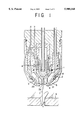
- a plasma torch which has previously been used in a plasma cutting machine is so constructed as shown in FIG. 1 of the drawings attached hereto, and is provided in its central portion with an electrode 1, inside of which there is formed a cooling chamber 8. Also, outside of the electrode 1 there is formed a plasma gas passage 2, and a nozzle 3 is disposed so as to surround the electrode 1 via the plasma gas passage 2. Also, outside of a forward end of the nozzle 3 there are formed a cooling chamber 9 and a secondary gas passage 4 along with a shield cap 5 surrounding the cooling chamber 9 and the secondary gas passage 4.
- a cutting process with a plasma torch of such a construction is carried out by generating a plasma arc 7 that constitutes a main arc between the electrode 1 and a workpiece 6 while causing a plasma gas 20 to flow through the plasma gas passage 2.
- the plasma arc 7 is pinched and thereby narrowed and densified with an orifice 3a of the nozzle 3 and is elevated in temperature and accelerated therethrough so as to be flushed towards the workpiece 6 and so as to melt and remove a portion thereof for cutting it.
- a water coolant is circulated through the cooling chambers 8 and 9 which are provided in the interior of the electrode 1 and the exterior of the nozzle 3, respectively, so that they may both be cooled. Also, a secondary gas 21 is then flushed through the secondary gas passage 4 provided inside of the shield cap 5 so that the above mentioned plasma arc 7 may be surrounded by the secondary gas 21.
- the procedure of generating a plasma arc 7 as mentioned above is set forth below.
- a high frequency voltage is applied across the electrode 1 and the nozzle 3 to cause a spark discharge between them, resulting in the occurrence of a pilot arc.
- the discharge spot of the pilot arc on the side of the electrode 1 is moved to the center of the forward end thereof while the discharge spot on the side of the nozzle 3 passing through the orifice 3a thereof is moved to a region of the outlet thereof, eventually reaching the surface of the workpiece 6, and thus establishing a plasma arc 7.
- the electric power between the electrode 1 and the nozzle 3 ceases being supplied.
- the plasma arc 7 is then pinched and thereby narrowed and densified with the orifice 3a of the nozzle 3 to result in a high temperature and high velocity flushing jet stream, which acts to form a cut groove of a small width in the workpiece 6 and to allow cutting thereof to proceed.
- the electrode 1 and the nozzle 3 are exposed to an elevated temperature by the plasma arc 7, they are, as mentioned above, cooled by the water coolant or air.
- the electrode 1 which will be elevated by a temperature of several thousand degrees due to the thermo electron emission, in order for its wear to be lowered, is composed of a high melting point material.
- a material if the plasma gas 20 contains oxygen, may be hafnium and, if it is a non-oxidizing gas not containing oxygen, may be tungsten.
- the kind of plasma gas 20 that has been employed is related to the material of the workpiece 6.
- the plasma gas 20 makes use of oxygen.
- a stainless material or an aluminum material is to be cut, the plasma gas 20 makes use of a non-oxidizing gas not containing oxygen.
- the non-oxidizing gas may be composed of a single component gas such as argon or hydrogen or a mixture thereof.
- a plasma arc 7 at a high temperature and with a high velocity is flushed out of the nozzle 3, thereby locally melting a workpiece 6 and a portion of the molten metal thereof is blown off to form a cut groove therein, whereby the workpiece 6 continues to be cut.
- the cutting quality of plasma cutting significantly depends on the configuration of the nozzle 3 through which the plasma arc 7 is pinched and thereby narrowed and densified for flushing out thereof. If the nozzle 3 wears so as to be deformed in configuration and the orifice 3a thereof is enlarged in diameter, the cutting quality should deteriorate.
- a plasma cutting machine in the prior art is designed to generate a pilot arc between the electrode 1 and the nozzle 3 before a main arc is initiated and, if an electrical conduction is established between the electrode 1 and a workpiece 6 with the pilot arc as a pilot flame, to form a plasma arc 7 constituting the main arc, and then, if this occurs, the supply of the electric power to the nozzle 3 is ceased so as to terminate the pilot arc. Thereafter, cutting will proceed with the main arc.
- the spot (arcing spot) P sustaining the pilot arc 17 is exposed to the arc of a high temperature. Also, an air entraining flow 18 is produced in the vicinity of the forward end of the nozzle 3 such that air may be drawn so as to flow into the orifice 3a of the nozzle 3. For this reason, if the plasma gas is composed of a non-oxidizing gas, damage 19 may develop due to oxidation in the orifice 3a of the nozzle 3. Consequently, each time a cutting operation is carried out, the wear of the nozzle 3 unavoidably proceeds due to a pilot arc 17 which is generated when the arc is initiated.
- the pilot arc 17 is generated from a spark discharge that is caused when, initially at the start of an arc, a high frequency high voltage is applied across the electrode 1 and the nozzle 3.
- the pilot arc 17 is generated across the shortest distance between the electrode 1 and the nozzle 3. Subsequently, floating on a flow of the plasma gas 20, the arcing spot on the side of the electrode 1 is moved to the center of the forward end thereof whereas the arcing spot P on the side of the nozzle 3 passing through the orifice 3a thereof is moved to a region of the outlet of the nozzle orifice 3a, and then stays in the vicinity of the outlet thereof until a main arc is generated.
- the present invention has been made with the foregoing problems taken into account and has as its object to provide a plasma cutting method which is capable of markedly enhancing the durability of the nozzle, maintaining an acceptable cutting quality over a prolonged time period, reducing the machine's running cost, and realizing an enhancement of the machine's productivity.
- a plasma cutting method for use with a plasma cutting apparatus having a nozzle with an orifice whereby a plasma arc is pinched and thereby narrowed and densified and a secondary gas flushing means for delivering a secondary gas so as to surround a forward end portion of the nozzle.
- a non-oxidizing gas is caused to flow as a plasma gas to start the arc and a non-oxidizing gas is caused to flow as the secondary gas to start the arc so that a non-oxidizing gaseous atmosphere may prevail in the vicinity of an outlet of the nozzle.
- a secondary gas to start the arc is flushed so as to surround the orifice of the nozzle outside thereof so that the atmosphere may not be drawn into to the orifice and the secondary gas is also constituted by a non-oxidizing gas without oxygen as is the plasma gas to establish the state in which oxygen is not existent in the vicinity of the orifice of the nozzle, it can be seen that the wear of the orifice of the nozzle will largely be reduced.
- the plasma gas may be switched from the non-oxidizing gas to oxygen or a gas that contains oxygen, substantially concurrently with a shift from a pilot arc into a main arc.
- the step of switching the plasma gas should be effected when the pilot arc is generated.
- the secondary gas may be switched from the non-oxidizing gas to oxygen or a gas that contains oxygen, substantially concurrently with a shifting from the pilot arc to the main arc.
- the steps of switching the plasma gas and switching the secondary gas should be both effected when the pilot arc is generated or when the main arc is generated.
- the non-oxidizing plasma gas and secondary gas which are caused to flow when the arc is started, may both be nitrogen.
- the plasma gas which is caused to flow substantially when and after the pilot arc is shifted into the main arc and while a cutting process is continued, may be oxygen and the secondary gas may then be air or a mixed gas of oxygen and nitrogen.
- the plasma gas which is caused to flow substantially when and after pilot arc is shifted into a main arc and while a cutting process is continued, may be a non-oxidizing gas.
- the secondary gas that is caused to flow substantially when and after the pilot arc is shifted into the main arc may be a non-oxidizing gas.
- the plasma gas and the secondary gas should both be nitrogen.
- FIG. 1 is a cross sectional view that shows an example of the plasma torch for use in a plasma cutting method of the prior art
- FIG. 2 is a cross sectional view that shows the state in which a nozzle is wearing off due to a pilot arc when an arc is initiated in the plasma cutting method of the prior art:
- FIG. 3 is a cross sectional view that shows an example of the plasma torch for use in a plasma cutting method according to the present invention:
- FIG. 4 is a cross sectional view that shows another example of the plasma torch for use in the plasma cutting method according to the present invention.
- FIG. 5 is a cross sectional view that shows still another example of the plasma torch for use in the plasma cutting method according to the present invention.
- FIG. 6 is a circuit diagram that shows a gas supply circuit for use where only a plasma gas is switched in the practice of the method according to the present invention
- FIG. 7 is a circuit diagram that shows a gas supply circuit for use where both the plasma gas and a secondary gas are switched in the practice of the method according to the present invention
- FIG. 8 is a timing diagram that shows an example of the operation for use where only the plasma gas is switched in the practice of the method according to the present invention
- FIG. 9 is a timing diagram that shows another example of the operation for use where only the plasma gas is switched in the practice of the method according to the present invention.
- FIG. 10 is a timing diagram that shows an example of the operation for use where both the plasma gas and the secondary gas are switched in the practice of the method according to the present invention.
- FIG. 11 is a timing diagram that shows another example of the operation for use where both the plasma gas and the secondary gas are switched in and the secondary gas are switched in the practice of the method according to the present invention.
- the method according to the present invention is carried out by using a plasma torch of a typical construction as shown in FIG. 3.
- a non-oxidizing gas not containing oxygen is caused to flow as a plasma gas 30, and a secondary gas 31 which is a non-oxidizing gas without oxygen is also caused to flow and be discharged outside of a nozzle 3 so as to surround an orifice 3a so that the atmosphere may not be the atmosphere may not be drawn into the plasma gas.
- the plasma torch used had a secondary gas supply means for delivering a secondary gas so as to surround a forward end portion of the nozzle.
- the plasma gas is oxygen, and the secondary gas is air.
- the plasma gas is nitrogen, and the secondary gas is air.
- the plasma gas is nitrogen, and the secondary gas is nitrogen.
- the plasma gas had a pressure of 2.0 kg/cm 2 and the secondary gas had a pressure of 3.5 kg/cm 2 with a current value of 50 amperes, an arcing number of 50 times and an arcing time duration of 3 seconds.
- the wear of the orifice of the nozzle can be largely reduced.
- the secondary gas 31 functions to shield a plasma gas stream, which contributes to a cutting process, from the atmosphere, that is, the secondary 31 serves to shield the outlet of the nozzle 3 from the atmosphere so that the plasma arc 7 is pinched and thereby narrowed and densified, and whose dimensional accuracy decisively affects the cutting quality.
- the forward end portion of a shield cap 5, that constitutes or defines a secondary gas passage 4 is so configured that as shown in FIG. 3, it may generally be tapered towards the torch forward end side and may thus be able to better shield the nozzle forward end portion efficiently with the secondary gas 31. Then, so that with the aid of the secondary gas 31 there may be no disturbance in the plasma arc 7 which is flushed out of the nozzle 3, the nozzle 3, an opening portion 5a of the shield cap 5 must have a diameter that is greater than that of the orifice 3a of the nozzle 3.
- the means for flushing the said secondary gas 31 include one in which the shield ca 5 is made cylindrical as shown in FIG. 4 and in which as shown in FIG. 5 the outlet of the nozzle 3 has a secondary gas flushing nozzle 16 located at a side thereto which is adapted to laterally discharge a secondary gas 31 against the outlet and thereby to shield the latter from the atmosphere.
- a supply circuit for the plasma gas 30 and the secondary gas 31 for carrying out the method according to the present invention is constructed as shown in FIG. 6 or 7.
- the circuit includes a non-oxidizing gas supply circuit 10 and an oxidizing supply circuit 11.
- the arc initiating plasma arc gas on/off valve 12 will be closed and at the same time a cutting plasma gas on/off valve 14 will be opened to switch the plasma gas from the non-oxidizing gas to oxygen or a gas that contains oxygen. Then, by permitting the latter to flow, a cutting operation will be initiated.
- FIG. 8 The timing diagram for the switching steps which are then performed is shown in FIG. 8 or 9.
- the concurrent switching steps for both the valves 12 and 14 are effected when a pilot arc is generated.
- the concurrent switching steps for both the valves 12 and 14 are effected when a main arc is generated.
- both the plasma gas 30 and the secondary gas 31 are designed to be switched, in order to completely replace the gases within the circuits before a plasma arc is generated, a predetermined time interval before the arc is initiated the arc initiating plasma gas on/off valve 12 will be opened to cause a non-oxidizing gas to flow as the plasma gas 30 through the plasma gas passage 2 whereas the arc initiating secondary gas on/off valve 13 will be opened to cause a non-oxidizing gas to flow as the secondary gas 31 through the secondary gas passage 4, to establish the state in which no oxygen is existent in the vicinity of the outlet of the nozzle 3, in which state a pilot arc is generated to initiate an arc.
- the arc initiating plasma gas on/off valve 12 will be closed and at the same time the cutting plasma gas on/off valve 14 will be opened to switch the plasma gas 30 from the non-oxidizing gas to oxygen or a gas that contains oxygen. Then, the arc initiating secondary gas on/off valve 13 will be closed and at the same time a cutting secondary gas on/off valve 15 will be opened to switch the secondary gas 31 from the non-oxidizing gas to oxygen or a gas that contains oxygen. Then, by permitting the latter to flow, a cutting operation commences.
- FIG. 10 or 11 The timing diagram for the switching steps which are then performed for both the gases 30 and 31 is shown in FIG. 10 or 11.
- the concurrent switching steps for all the valves 12, 13, 14 and 15 are effected when a pilot arc is generated.
- the concurrent switching steps for all the valves 12, 13, 14 and 15 are effected when a main arc is generated.
- the time at which each of the plasma and secondary gases is switched represents the time at which a signal is received that is produced when the occurrence of the pilot arc or the occurrence of the main arc is detected.
- a time at which a gas is switched should better be established with the time of replacement of a initiating non-oxidizing gas and a cutting oxidizing gas at the orifice portion of the nozzle 3 taken into consideration. Desirably the replacement should be completed at the orifice portion of the nozzle 3 at the same time as a main arc occurs and then it would have no adverse influence on a cutting operation. However, the time period required for the replacement to be completed would actually be longer or shorter depending on the length of a gas piping.
- the time at which a gas is switched may be when a signal indicating the occurrence of a main arc is received.
- the gas piping length is so long that it takes longer to replace a gas, it may be an extended time before a main arc is generated.
- An influence of gas replacement on a cutting process could be held at a minimum if the timing of a gas switching step is so established when the time interval for the gas replacement is short in sequence so that any of a pilot arc occurrence sensing signal, a high frequency occurrence sensing signal and a start signal may be detected to switch the relevant on/off valve.
- an oxidizing gas is represented by oxygen, air or a gas that contains oxygen such as a mixed gas of oxygen and nitrogen whereas a non-oxidizing gas is represented by a so-called inert gas such as nitrogen, argon, helium and hydrogen singly or in combination.
- oxygen is utilized as the plasma gas 30.
- nitrogen is utilized both as the plasma gas 30 and the secondary gas 31 when an arc is started, and oxygen is utilized as the plasma gas 30 and air or a gas containing oxygen is utilized as the secondary gas 31 after a pilot arc has been generated and while a cutting process proceeds.
- oxygen is utilized as the plasma gas 30 for cutting because the cutting is promoted by a heat of reaction that is produced from the oxidation reaction between mild steel and an oxygen plasma.
- the secondary gas 31 should be desirably a gas that contains oxygen. This is because if a non-oxidizing gas were utilized the oxygen purity of the plasma gas 30 would, be lowered and would exert a deleterious effect on plasma cutting. Also, the reason why nitrogen is utilized as the non-oxidizing gas when a pilot arc is generated is that, it if made into a plasma, it would have characteristics which are substantially identical to those of oxygen and would make the arc less unstable when it is switched.
- a non-oxidizing gas not containing oxygen is utilized as the plasma gas 30.
- the non-oxidizing gas includes nitrogen, argon, hydrogen and so forth singly or in a combination.
- the nozzle wear due to a pilot arc as mentioned above should proceed although it is much less than with the oxygen plasma. For this reason, in a plasma cutting machine using such a non-oxidizing gas, it will be seen that the durability of the nozzle 3 can be enhanced by causing a non-oxidizing secondary gas 31 to flow when a pilot arc is generated.
- the orifice of the nozzle 3 can be shielded from the atmosphere when an arc is initiated, thus preventing it from being oxidized and damaged.
Landscapes
- Engineering & Computer Science (AREA)
- Physics & Mathematics (AREA)
- Plasma & Fusion (AREA)
- Spectroscopy & Molecular Physics (AREA)
- Mechanical Engineering (AREA)
- Arc Welding In General (AREA)
- Plasma Technology (AREA)
Applications Claiming Priority (3)
| Application Number | Priority Date | Filing Date | Title |
|---|---|---|---|
| JP7-23894 | 1995-02-13 | ||
| JP7023894A JPH08215856A (ja) | 1995-02-13 | 1995-02-13 | プラズマ切断方法 |
| PCT/JP1996/000304 WO1996025265A1 (fr) | 1995-02-13 | 1996-02-13 | Procede de decoupage par plasma |
Publications (1)
| Publication Number | Publication Date |
|---|---|
| US5900168A true US5900168A (en) | 1999-05-04 |
Family
ID=12123169
Family Applications (1)
| Application Number | Title | Priority Date | Filing Date |
|---|---|---|---|
| US08/894,062 Expired - Fee Related US5900168A (en) | 1995-02-13 | 1996-02-13 | Plasma cutting method |
Country Status (5)
| Country | Link |
|---|---|
| US (1) | US5900168A (ja) |
| EP (1) | EP0810052A4 (ja) |
| JP (1) | JPH08215856A (ja) |
| KR (1) | KR100272917B1 (ja) |
| CA (1) | CA2212666A1 (ja) |
Cited By (8)
| Publication number | Priority date | Publication date | Assignee | Title |
|---|---|---|---|---|
| US6248972B1 (en) * | 1999-04-30 | 2001-06-19 | Komatsu Ltd. | Plasma cutting method, device and gas supply system for plasma cutting torch |
| US6337460B2 (en) * | 2000-02-08 | 2002-01-08 | Thermal Dynamics Corporation | Plasma arc torch and method for cutting a workpiece |
| US20060102606A1 (en) * | 2004-11-16 | 2006-05-18 | Twarog Peter J | Plasma arc torch having an electrode with internal passages |
| US20060102598A1 (en) * | 2004-11-16 | 2006-05-18 | Hypertherm, Inc. | Plasma arc torch having an electrode with internal passages |
| US20060163220A1 (en) * | 2005-01-27 | 2006-07-27 | Brandt Aaron D | Automatic gas control for a plasma arc torch |
| US20100326966A1 (en) * | 2009-06-26 | 2010-12-30 | Institute Of Nuclear Energy Research Atomic Energy Council, Executive Yuan | Multi-Gas Mixer and Device for Supplying Gas Mixture to Plasma Torch |
| RU2584367C1 (ru) * | 2015-03-11 | 2016-05-20 | Общество с ограниченной ответственностью Научно-производственное объединение "Полигон" | Плазмотрон |
| CN111790968A (zh) * | 2020-09-02 | 2020-10-20 | 南通阳光焊割设备有限公司 | 一种多工位等离子切割机及其切割方法 |
Families Citing this family (5)
| Publication number | Priority date | Publication date | Assignee | Title |
|---|---|---|---|---|
| JPH11342476A (ja) * | 1998-05-29 | 1999-12-14 | Daihen Corp | ステンレス鋼のエアープラズマ切断方法および切断装置 |
| DE202004021663U1 (de) * | 2004-10-08 | 2010-05-12 | Kjellberg Finsterwalde Plasma Und Maschinen Gmbh | Plasmabrenner |
| JP6168734B2 (ja) * | 2012-06-01 | 2017-07-26 | 新日鐵住金株式会社 | 金属のプラズマ切断方法及び金属のプラズマ切断装置 |
| KR101452894B1 (ko) * | 2012-12-24 | 2014-10-23 | 주식회사 포스코 | 고망간강의 절단방법 |
| GB2568106B (en) * | 2017-11-07 | 2022-09-21 | Tetronics Tech Limited | Plasma Torch Assembly |
Citations (15)
| Publication number | Priority date | Publication date | Assignee | Title |
|---|---|---|---|---|
| JPS5639174A (en) * | 1979-09-05 | 1981-04-14 | Hitachi Ltd | Plasma torch |
| JPS6055221A (ja) * | 1983-09-06 | 1985-03-30 | Anritsu Corp | 走間厚み計 |
| JPS6192782A (ja) * | 1984-10-15 | 1986-05-10 | Koike Sanso Kogyo Co Ltd | プラズマ切断スタート方法 |
| JPS6483376A (en) * | 1987-09-28 | 1989-03-29 | Komatsu Mfg Co Ltd | Method for operating plasma torch |
| WO1991016165A1 (en) * | 1990-04-24 | 1991-10-31 | Hypertherm, Inc. | Improved process and apparatus for reducing electrode wear in a plasma arc torch |
| JPH05174994A (ja) * | 1991-12-24 | 1993-07-13 | Origin Electric Co Ltd | プラズマア−ク装置およびパイロットア−ク発生方法 |
| JPH0671670A (ja) * | 1992-08-27 | 1994-03-15 | Toray Ind Inc | 樹脂フィルム製造装置の水膜形成装置 |
| JPH0760450A (ja) * | 1993-08-25 | 1995-03-07 | Nippon Steel Corp | プラズマ切断方法 |
| US5414237A (en) * | 1993-10-14 | 1995-05-09 | The Esab Group, Inc. | Plasma arc torch with integral gas exchange |
| US5424507A (en) * | 1991-03-20 | 1995-06-13 | Kabushiki Kaisha Komatsu Seisakusho | Controlling working gas flow rate and arc current level in plasma arc cutting machine |
| JPH08288095A (ja) * | 1995-04-19 | 1996-11-01 | Komatsu Ltd | プラズマアークトーチ用電極 |
| US5591357A (en) * | 1988-06-07 | 1997-01-07 | Hypertherm, Inc. | Plasma arc cutting process and apparatus using an oxygen-rich gas shield |
| JPH0924473A (ja) * | 1995-07-12 | 1997-01-28 | Komatsu Ltd | プラズマトーチ |
| US5653895A (en) * | 1993-10-14 | 1997-08-05 | Komatsu Ltd. | Plasma cutting method suitable for cutting thin stainless steel sheet material |
| US5653896A (en) * | 1992-12-11 | 1997-08-05 | Hypertherm, Inc. | Process for high quality plasma arc and laser cutting of stainless steel and aluminum |
-
1995
- 1995-02-13 JP JP7023894A patent/JPH08215856A/ja active Pending
-
1996
- 1996-02-13 EP EP96901992A patent/EP0810052A4/en not_active Withdrawn
- 1996-02-13 KR KR1019970705541A patent/KR100272917B1/ko not_active IP Right Cessation
- 1996-02-13 CA CA002212666A patent/CA2212666A1/en not_active Abandoned
- 1996-02-13 US US08/894,062 patent/US5900168A/en not_active Expired - Fee Related
Patent Citations (15)
| Publication number | Priority date | Publication date | Assignee | Title |
|---|---|---|---|---|
| JPS5639174A (en) * | 1979-09-05 | 1981-04-14 | Hitachi Ltd | Plasma torch |
| JPS6055221A (ja) * | 1983-09-06 | 1985-03-30 | Anritsu Corp | 走間厚み計 |
| JPS6192782A (ja) * | 1984-10-15 | 1986-05-10 | Koike Sanso Kogyo Co Ltd | プラズマ切断スタート方法 |
| JPS6483376A (en) * | 1987-09-28 | 1989-03-29 | Komatsu Mfg Co Ltd | Method for operating plasma torch |
| US5591357A (en) * | 1988-06-07 | 1997-01-07 | Hypertherm, Inc. | Plasma arc cutting process and apparatus using an oxygen-rich gas shield |
| WO1991016165A1 (en) * | 1990-04-24 | 1991-10-31 | Hypertherm, Inc. | Improved process and apparatus for reducing electrode wear in a plasma arc torch |
| US5424507A (en) * | 1991-03-20 | 1995-06-13 | Kabushiki Kaisha Komatsu Seisakusho | Controlling working gas flow rate and arc current level in plasma arc cutting machine |
| JPH05174994A (ja) * | 1991-12-24 | 1993-07-13 | Origin Electric Co Ltd | プラズマア−ク装置およびパイロットア−ク発生方法 |
| JPH0671670A (ja) * | 1992-08-27 | 1994-03-15 | Toray Ind Inc | 樹脂フィルム製造装置の水膜形成装置 |
| US5653896A (en) * | 1992-12-11 | 1997-08-05 | Hypertherm, Inc. | Process for high quality plasma arc and laser cutting of stainless steel and aluminum |
| JPH0760450A (ja) * | 1993-08-25 | 1995-03-07 | Nippon Steel Corp | プラズマ切断方法 |
| US5414237A (en) * | 1993-10-14 | 1995-05-09 | The Esab Group, Inc. | Plasma arc torch with integral gas exchange |
| US5653895A (en) * | 1993-10-14 | 1997-08-05 | Komatsu Ltd. | Plasma cutting method suitable for cutting thin stainless steel sheet material |
| JPH08288095A (ja) * | 1995-04-19 | 1996-11-01 | Komatsu Ltd | プラズマアークトーチ用電極 |
| JPH0924473A (ja) * | 1995-07-12 | 1997-01-28 | Komatsu Ltd | プラズマトーチ |
Non-Patent Citations (5)
| Title |
|---|
| Patent Abstracts of Japan, vol. 10, No. 267 (M 516), Sep. 11, 1986 & JP 61 092782A (Koike Sanso Kogyo Co. Ltd), May 10, 1996. * |
| Patent Abstracts of Japan, vol. 10, No. 267 (M-516), Sep. 11, 1986 & JP 61 092782A (Koike Sanso Kogyo Co. Ltd), May 10, 1996. |
| Patent Abstracts of Japan, vol. 13, No. 289 (M 845), Jul. 5, 1989 & JP 01 083376A (Komatsu Ltd), Mar. 29, 1989. * |
| Patent Abstracts of Japan, vol. 13, No. 289 (M-845), Jul. 5, 1989 & JP 01 083376A (Komatsu Ltd), Mar. 29, 1989. |
| Patent Abstracts of Japan, vol. 95, No. 6, Jul. 31, 1995 & JP 07060450A (Nippon Steel Corp), Mar. 7, 1995. * |
Cited By (18)
| Publication number | Priority date | Publication date | Assignee | Title |
|---|---|---|---|---|
| US6248972B1 (en) * | 1999-04-30 | 2001-06-19 | Komatsu Ltd. | Plasma cutting method, device and gas supply system for plasma cutting torch |
| US6337460B2 (en) * | 2000-02-08 | 2002-01-08 | Thermal Dynamics Corporation | Plasma arc torch and method for cutting a workpiece |
| US7375303B2 (en) * | 2004-11-16 | 2008-05-20 | Hypertherm, Inc. | Plasma arc torch having an electrode with internal passages |
| US20060102606A1 (en) * | 2004-11-16 | 2006-05-18 | Twarog Peter J | Plasma arc torch having an electrode with internal passages |
| US20060102598A1 (en) * | 2004-11-16 | 2006-05-18 | Hypertherm, Inc. | Plasma arc torch having an electrode with internal passages |
| US8680425B2 (en) | 2004-11-16 | 2014-03-25 | Hypertherm, Inc. | Plasma arc torch having an electrode with internal passages |
| US20080237202A1 (en) * | 2004-11-16 | 2008-10-02 | Hypertherm, Inc. | Plasma Arc Torch Having an Electrode With Internal Passages |
| US7375302B2 (en) * | 2004-11-16 | 2008-05-20 | Hypertherm, Inc. | Plasma arc torch having an electrode with internal passages |
| US20060163220A1 (en) * | 2005-01-27 | 2006-07-27 | Brandt Aaron D | Automatic gas control for a plasma arc torch |
| US20080210670A1 (en) * | 2005-01-27 | 2008-09-04 | Hypertherm, Inc. | Method and apparatus for automatic gas control for a plasma arch torch |
| US20080006614A1 (en) * | 2005-01-27 | 2008-01-10 | Hypertherm, Inc. | Method and apparatus for automatic gas control for a plasma arc torch |
| US8541710B2 (en) | 2005-01-27 | 2013-09-24 | Hypertherm, Inc. | Method and apparatus for automatic gas control for a plasma arc torch |
| US20060163216A1 (en) * | 2005-01-27 | 2006-07-27 | Hypertherm, Inc. | Automatic gas control for a plasma arc torch |
| US8809728B2 (en) | 2005-01-27 | 2014-08-19 | Hypertherm, Inc. | Method and apparatus for automatic gas control for a plasma arc torch |
| US20100326966A1 (en) * | 2009-06-26 | 2010-12-30 | Institute Of Nuclear Energy Research Atomic Energy Council, Executive Yuan | Multi-Gas Mixer and Device for Supplying Gas Mixture to Plasma Torch |
| US8362388B2 (en) * | 2009-06-26 | 2013-01-29 | Institute Of Nuclear Energy Research Atomic Energy Council, Executive Yuan | Multi-gas mixer and device for supplying gas mixture to plasma torch |
| RU2584367C1 (ru) * | 2015-03-11 | 2016-05-20 | Общество с ограниченной ответственностью Научно-производственное объединение "Полигон" | Плазмотрон |
| CN111790968A (zh) * | 2020-09-02 | 2020-10-20 | 南通阳光焊割设备有限公司 | 一种多工位等离子切割机及其切割方法 |
Also Published As
| Publication number | Publication date |
|---|---|
| CA2212666A1 (en) | 1996-08-22 |
| KR100272917B1 (ko) | 2000-11-15 |
| EP0810052A1 (en) | 1997-12-03 |
| JPH08215856A (ja) | 1996-08-27 |
| KR19980702146A (ko) | 1998-07-15 |
| EP0810052A4 (en) | 1998-04-22 |
Similar Documents
| Publication | Publication Date | Title |
|---|---|---|
| US5900168A (en) | Plasma cutting method | |
| KR930005953B1 (ko) | 개량 플라즈마 아아크 토오치 시동방법 | |
| US5464962A (en) | Electrode for a plasma arc torch | |
| US5756959A (en) | Coolant tube for use in a liquid-cooled electrode disposed in a plasma arc torch | |
| US5653895A (en) | Plasma cutting method suitable for cutting thin stainless steel sheet material | |
| US6337460B2 (en) | Plasma arc torch and method for cutting a workpiece | |
| EP0202077A1 (en) | Single torch-type plasma spray coating method and apparatus therefor | |
| US3597649A (en) | Device for plasma-arc treatment of materials | |
| US4777343A (en) | Plasma arc apparatus | |
| US5310988A (en) | Electrode for high current density plasma arc torch | |
| US4059743A (en) | Plasma arc cutting torch | |
| US6677551B2 (en) | Process for operating a plasma arc torch | |
| EP0790756B2 (en) | Plasma arc cutting process using an oxygen-rich gas shield | |
| AU1772592A (en) | Plasma arc cutting process and apparatus using an oxygen-rich gas shield | |
| EP0375747A1 (en) | NOZZLE PROTECTION FOR PLASMA ARC WELDING TORCHES. | |
| US4321454A (en) | Method of and welding torch for arc welding | |
| US3950629A (en) | Electrical arc-welding torches | |
| JPH05226096A (ja) | プラズマトーチとプラズマジェットの発生方法 | |
| US3344256A (en) | Method for producing arcs | |
| KR20150031472A (ko) | 플라즈마 아크 절단 토치용 전극 | |
| US6069336A (en) | Plasma or TIG welding or cutting process with a non-oxidizing gas having a low H2 O and/or O2 impurity content | |
| JPS63154272A (ja) | プラズマト−チ | |
| JPS63154273A (ja) | プラズマト−チ | |
| US20210204387A1 (en) | Methods for operating a plasma torch | |
| WO1996025265A1 (fr) | Procede de decoupage par plasma |
Legal Events
| Date | Code | Title | Description |
|---|---|---|---|
| AS | Assignment |
Owner name: KOMATSU INDUSTRIES CORPORATION, JAPAN Free format text: ASSIGNMENT OF ASSIGNORS INTEREST;ASSIGNORS:SAIO, KATSUO;YAMAGUCHI, YOSHIHIRO;REEL/FRAME:008828/0858 Effective date: 19970729 Owner name: KOMATSU LTD., JAPAN Free format text: ASSIGNMENT OF ASSIGNORS INTEREST;ASSIGNORS:SAIO, KATSUO;YAMAGUCHI, YOSHIHIRO;REEL/FRAME:008828/0858 Effective date: 19970729 |
|
| FEPP | Fee payment procedure |
Free format text: PAYOR NUMBER ASSIGNED (ORIGINAL EVENT CODE: ASPN); ENTITY STATUS OF PATENT OWNER: LARGE ENTITY |
|
| FPAY | Fee payment |
Year of fee payment: 4 |
|
| FPAY | Fee payment |
Year of fee payment: 8 |
|
| REMI | Maintenance fee reminder mailed | ||
| LAPS | Lapse for failure to pay maintenance fees | ||
| STCH | Information on status: patent discontinuation |
Free format text: PATENT EXPIRED DUE TO NONPAYMENT OF MAINTENANCE FEES UNDER 37 CFR 1.362 |
|
| FP | Lapsed due to failure to pay maintenance fee |
Effective date: 20110504 |