US583990A - David frank - Google Patents
David frank Download PDFInfo
- Publication number
- US583990A US583990A US583990DA US583990A US 583990 A US583990 A US 583990A US 583990D A US583990D A US 583990DA US 583990 A US583990 A US 583990A
- Authority
- US
- United States
- Prior art keywords
- frame
- rail
- ornamental
- bedstead
- secured
- Prior art date
- Legal status (The legal status is an assumption and is not a legal conclusion. Google has not performed a legal analysis and makes no representation as to the accuracy of the status listed.)
- Expired - Lifetime
Links
- 239000002184 metal Substances 0.000 description 7
- 229910001369 Brass Inorganic materials 0.000 description 4
- 239000010951 brass Substances 0.000 description 4
- 238000010276 construction Methods 0.000 description 3
Images
Classifications
-
- A—HUMAN NECESSITIES
- A47—FURNITURE; DOMESTIC ARTICLES OR APPLIANCES; COFFEE MILLS; SPICE MILLS; SUCTION CLEANERS IN GENERAL
- A47C—CHAIRS; SOFAS; BEDS
- A47C19/00—Bedsteads
- A47C19/02—Parts or details of bedsteads not fully covered in a single one of the following subgroups, e.g. bed rails, post rails
- A47C19/021—Bedstead frames
- A47C19/022—Head or foot boards
Definitions
- DAVID FRANK OF BROOKLYN, NEW? YORK, ASSIGNOR OF ONE-HALF TO JOHN TROUNSTINE, OF NEYV YORK, N. Y.
- the invention relates to improvements in metal bedsteads; and it consists in the novel construction hereinafter described and claimed, applicable to the head or foot frames of the bed or to both said head and foot frames.
- the object of the invention is to provide a new construction affording means within the head or foot frame for supporting, and maintaining an ornamental frame inclosing a mirror, picture, or the like, the whole producing an attractive bedstead-frame of a very desirable character.
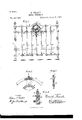
- Figure l is a front elevation of the footframe of a metal bedstead constructed in accordance with and embodying the invention.
- Fig. 2 is an enlarged detached view, partly in section, of the upper central portion of the foot-frame and the ornamental frame supported therein, this figure illustrating, on an enlarged scale, the means for maintaining the upper end of the ornamental mirror-frame.
- Fig. 3 is a vertical section of same on the dotted line 3 3 of Fig. 2
- Fig. 4 is a vertical section through a portion of the foot-frame and mirror-frame on the dotted line 4 4 of Fig. 1.
- a B denote the upper and lower main transverse rails or bars of the main foot-frame, and O C the corner or end posts, to which the said rails A B are secured in the usual manner.
- Above the upper rail A is the ornamental brass rail D, which is connected at its ends with the corner-posts O or ornamental caps carried by said posts.
- transverse rails A E Intermediate the transverse rails A E are the series of vertical rails or bars D, which at their ends are secured to said transverse rails by the cast boxes E.
- the upper main rail A at its center curves downward, as at F, and the upper ornamental brass rail D at its center curves upward, as at G, to correspond with the central curvature of the rail A and to combine with said rail A to form a substantially circular frame or space to receive the ornamental frame H, which may be utilized to hold a mirror, picture, or the like.
- the frame His cast in an ornamental outline and carries at its upper end the screw or belt I, which passes upward'through an aperture in, the center of the brass rail D and receives upon its end, which projects above said rail D, the ornamental ball or knob J, whose main purpose is to conceal the upper end of the screw or bolt I and to aid in effectually and securely maintaining the upper end of the ornamental frame H in place.
- the box E which is at the center of the rail A and at the lower point of the curved portion F of said rail, is provided at its rear face with the upwardly-projecting lug K, against which the lower edge of the ornamental frame H is socured by means of the screw L and ornamental knob or ball M.
- the lower edge of the ornamental frame H rests directly upon the upper end of the box E and is bound against the lug K by means of the said screw L and knob or ball M.
- the ornamental frame H is thus secured at its lower end against the lug K of the box E and at its upper end by means of the screw I and knob J, and the parts securing the frame H are so disposed that the frame H occupies a vertical position within the bed-frame and substantially in line with the rails D and posts O.
- the frame H is ornamental in itself, and when embodied in the head or foot frame of a metal bedstead greatly enhances the character thereof.
- the frame H is interposed between the upper main rail A and the upper ornamental brass rail D within a space specially provided for it, and the construction thus presented is of novel character and adds to the desirability of the bedstead as a whole.
- the box E having the rear lug extension K, forms a permanent part of the bed-frame and is at the intersecting point of the rail A and middle rail D, and hence while this box E serves its usual purposes it also affords the means for securing the lower edge of the frame H.
- the upper edge of the frame H is secured to the rail D at a point where there is no box IE, and at this point the frame is secured by the screw I or equivalent means engaging said rail D.
- the frame H is secured by means which are practically invisible from the front of the bed-frame, and they in no manner disfigure the bedstead.
- the ornamental frame H combined with the cast box E havin g the upward rear extension K and forming a permanentpart of the bed-frame and against which extension one edge of the said frame II is secured, and the screw at the opposite edge of said frame II and engaging a rail of said framewhereby said edge may be secured to said rail; substantially as set forth.
- the upper and lower main connected rails A, B In and forming a part of the frame of a metal rail or bar bedstead, the upper and lower main connected rails A, B, the central portion of the upper rail A being curved downward, combined with the ornamental top rail D whose central portion curves upward, the ornamental frame H set vertically within the space outlined by said oppositely-curved portions of the rails A, D, the cast box E having the upward rear extension K to receive the lower edge of said frame H at the center of the rail A, and the screw or pin at the upper edge of said frame H and piercing said rail D; substantially as set forth.
Landscapes
- Invalid Beds And Related Equipment (AREA)
Description
(No Model) B. FRANK.
METAL BEDSTEAD. No. 583,990. Patented June 8,1897.
' INVENTOH BY I --""'" ATTORNEY.
WITNESSES UNITED STATES PATENT FFICE.
DAVID FRANK, OF BROOKLYN, NEW? YORK, ASSIGNOR OF ONE-HALF TO JOHN TROUNSTINE, OF NEYV YORK, N. Y.
METAL BEDSTEAD.
SPECIFICATION forming part of Letters Patent No. 583,990, dated June 8, 1897. A li ati n filed March 5, 1897. Serial No. 625,929. (No model.)
To all 20720171, it 7221/41 con-corn:
Be it known that I, DAVID FRANK, a citizen of the United States, residing at Brooklyn, in the county of Kings and State of New York, have invented certain new and useful Improvements in Metal Bedsteads; and I do declare the following to be a full, clear, and exact description of the invention, such as will enable others skilled in the art to which it appertains to make and use the same, reference being had to the accompanying drawings, and to the letters of reference marked thereon, which form a part of this specification.
The invention relates to improvements in metal bedsteads; and it consists in the novel construction hereinafter described and claimed, applicable to the head or foot frames of the bed or to both said head and foot frames.
The object of the invention is to provide a new construction affording means within the head or foot frame for supporting, and maintaining an ornamental frame inclosing a mirror, picture, or the like, the whole producing an attractive bedstead-frame of a very desirable character.
The invention will be more fully understood from the detailed description hereinafter presented, reference being had to the accompanying drawings, in which Figure l is a front elevation of the footframe of a metal bedstead constructed in accordance with and embodying the invention. Fig. 2 is an enlarged detached view, partly in section, of the upper central portion of the foot-frame and the ornamental frame supported therein, this figure illustrating, on an enlarged scale, the means for maintaining the upper end of the ornamental mirror-frame. Fig. 3 is a vertical section of same on the dotted line 3 3 of Fig. 2, and Fig. 4 is a vertical section through a portion of the foot-frame and mirror-frame on the dotted line 4 4 of Fig. 1. In the drawings, A B denote the upper and lower main transverse rails or bars of the main foot-frame, and O C the corner or end posts, to which the said rails A B are secured in the usual manner. Above the upper rail A is the ornamental brass rail D, which is connected at its ends with the corner-posts O or ornamental caps carried by said posts.
Intermediate the transverse rails A E are the series of vertical rails or bars D, which at their ends are secured to said transverse rails by the cast boxes E. The upper main rail A at its center curves downward, as at F, and the upper ornamental brass rail D at its center curves upward, as at G, to correspond with the central curvature of the rail A and to combine with said rail A to form a substantially circular frame or space to receive the ornamental frame H, which may be utilized to hold a mirror, picture, or the like. The frame His cast in an ornamental outline and carries at its upper end the screw or belt I, which passes upward'through an aperture in, the center of the brass rail D and receives upon its end, which projects above said rail D, the ornamental ball or knob J, whose main purpose is to conceal the upper end of the screw or bolt I and to aid in effectually and securely maintaining the upper end of the ornamental frame H in place. The box E, which is at the center of the rail A and at the lower point of the curved portion F of said rail, is provided at its rear face with the upwardly-projecting lug K, against which the lower edge of the ornamental frame H is socured by means of the screw L and ornamental knob or ball M. The lower edge of the ornamental frame H rests directly upon the upper end of the box E and is bound against the lug K by means of the said screw L and knob or ball M.
The ornamental frame H is thus secured at its lower end against the lug K of the box E and at its upper end by means of the screw I and knob J, and the parts securing the frame H are so disposed that the frame H occupies a vertical position within the bed-frame and substantially in line with the rails D and posts O.
The frame H is ornamental in itself, and when embodied in the head or foot frame of a metal bedstead greatly enhances the character thereof. In the present instance the frame H is interposed between the upper main rail A and the upper ornamental brass rail D within a space specially provided for it, and the construction thus presented is of novel character and adds to the desirability of the bedstead as a whole.
The box E, having the rear lug extension K, forms a permanent part of the bed-frame and is at the intersecting point of the rail A and middle rail D, and hence while this box E serves its usual purposes it also affords the means for securing the lower edge of the frame H. The upper edge of the frame H is secured to the rail D at a point where there is no box IE, and at this point the frame is secured by the screw I or equivalent means engaging said rail D. The frame H is secured by means which are practically invisible from the front of the bed-frame, and they in no manner disfigure the bedstead.
lVhat I claim as my invention, and desire to secure by Letters Patent, is-
1. In and forming a part of the frame of a metal rail or bar bedstead, the ornamental frame H, combined with the cast box E havin g the upward rear extension K and forming a permanentpart of the bed-frame and against which extension one edge of the said frame II is secured, and the screw at the opposite edge of said frame II and engaging a rail of said framewhereby said edge may be secured to said rail; substantially as set forth.
' 2. In and forming a part of the frame of a metal rail or bar bedstead, the upper and lower main connected rails A, B, the central portion of the upper rail A being curved downward, combined with the ornamental top rail D whose central portion curves upward, the ornamental frame H set vertically within the space outlined by said oppositely-curved portions of the rails A, D, the cast box E having the upward rear extension K to receive the lower edge of said frame H at the center of the rail A, and the screw or pin at the upper edge of said frame H and piercing said rail D; substantially as set forth.
In testimony whereof I affix my signature in presence of two witnesses. I DAVID l RANK.
' YVitnesses:
CHAS. O. GILL, E. Jos. BE KNAP.
Publications (1)
| Publication Number | Publication Date |
|---|---|
| US583990A true US583990A (en) | 1897-06-08 |
Family
ID=2652662
Family Applications (1)
| Application Number | Title | Priority Date | Filing Date |
|---|---|---|---|
| US583990D Expired - Lifetime US583990A (en) | David frank |
Country Status (1)
| Country | Link |
|---|---|
| US (1) | US583990A (en) |
Cited By (1)
| Publication number | Priority date | Publication date | Assignee | Title |
|---|---|---|---|---|
| USD1074250S1 (en) * | 2023-10-09 | 2025-05-13 | Yuehua DENG | Bed |
-
0
- US US583990D patent/US583990A/en not_active Expired - Lifetime
Cited By (1)
| Publication number | Priority date | Publication date | Assignee | Title |
|---|---|---|---|---|
| USD1074250S1 (en) * | 2023-10-09 | 2025-05-13 | Yuehua DENG | Bed |
Similar Documents
| Publication | Publication Date | Title |
|---|---|---|
| US659089A (en) | Stool. | |
| US1215609A (en) | Reclining-couch. | |
| US277272A (en) | Chair | |
| US572253A (en) | Dayid frank | |
| US1075291A (en) | Bed. | |
| US754353A (en) | Bed-partition. | |
| US1370301A (en) | Bed-frame | |
| US178439A (en) | Improvement in hat-racks for chairs | |
| US725030A (en) | Spring-support for bed-bottoms. | |
| US491243A (en) | franks | |
| US606133A (en) | Convertible couch | |
| US1040693A (en) | Bedstead. | |
| US491244A (en) | Orrin g | |
| US516003A (en) | Chair-seat | |
| US530953A (en) | Support for canopy-rods in | |
| USD33963S (en) | Design for an end frame for bedsteads | |
| US634065A (en) | Iron bed. | |
| US419253A (en) | Spring for spring-beds and furniture | |
| USD24302S (en) | Design for a bedstead | |
| US1002844A (en) | Article of furniture. | |
| US168828A (en) | Improvement in chairs | |
| US1210924A (en) | Metallic bedstead. | |
| US524720A (en) | Benjamin t | |
| USD24711S (en) | Design for a bedstead | |
| US618289A (en) | Louts pet kill a |