US5828443A - Distance measuring apparatus - Google Patents
Distance measuring apparatus Download PDFInfo
- Publication number
- US5828443A US5828443A US08/607,512 US60751296A US5828443A US 5828443 A US5828443 A US 5828443A US 60751296 A US60751296 A US 60751296A US 5828443 A US5828443 A US 5828443A
- Authority
- US
- United States
- Prior art keywords
- distance
- discharge
- time
- measuring apparatus
- voltage
- Prior art date
- Legal status (The legal status is an assumption and is not a legal conclusion. Google has not performed a legal analysis and makes no representation as to the accuracy of the status listed.)
- Expired - Fee Related
Links
Images




Classifications
-
- G—PHYSICS
- G01—MEASURING; TESTING
- G01S—RADIO DIRECTION-FINDING; RADIO NAVIGATION; DETERMINING DISTANCE OR VELOCITY BY USE OF RADIO WAVES; LOCATING OR PRESENCE-DETECTING BY USE OF THE REFLECTION OR RERADIATION OF RADIO WAVES; ANALOGOUS ARRANGEMENTS USING OTHER WAVES
- G01S17/00—Systems using the reflection or reradiation of electromagnetic waves other than radio waves, e.g. lidar systems
-
- G—PHYSICS
- G01—MEASURING; TESTING
- G01S—RADIO DIRECTION-FINDING; RADIO NAVIGATION; DETERMINING DISTANCE OR VELOCITY BY USE OF RADIO WAVES; LOCATING OR PRESENCE-DETECTING BY USE OF THE REFLECTION OR RERADIATION OF RADIO WAVES; ANALOGOUS ARRANGEMENTS USING OTHER WAVES
- G01S17/00—Systems using the reflection or reradiation of electromagnetic waves other than radio waves, e.g. lidar systems
- G01S17/88—Lidar systems specially adapted for specific applications
- G01S17/93—Lidar systems specially adapted for specific applications for anti-collision purposes
- G01S17/931—Lidar systems specially adapted for specific applications for anti-collision purposes of land vehicles
-
- B—PERFORMING OPERATIONS; TRANSPORTING
- B60—VEHICLES IN GENERAL
- B60Q—ARRANGEMENT OF SIGNALLING OR LIGHTING DEVICES, THE MOUNTING OR SUPPORTING THEREOF OR CIRCUITS THEREFOR, FOR VEHICLES IN GENERAL
- B60Q9/00—Arrangement or adaptation of signal devices not provided for in one of main groups B60Q1/00 - B60Q7/00, e.g. haptic signalling
- B60Q9/008—Arrangement or adaptation of signal devices not provided for in one of main groups B60Q1/00 - B60Q7/00, e.g. haptic signalling for anti-collision purposes
-
- G—PHYSICS
- G01—MEASURING; TESTING
- G01S—RADIO DIRECTION-FINDING; RADIO NAVIGATION; DETERMINING DISTANCE OR VELOCITY BY USE OF RADIO WAVES; LOCATING OR PRESENCE-DETECTING BY USE OF THE REFLECTION OR RERADIATION OF RADIO WAVES; ANALOGOUS ARRANGEMENTS USING OTHER WAVES
- G01S7/00—Details of systems according to groups G01S13/00, G01S15/00, G01S17/00
- G01S7/48—Details of systems according to groups G01S13/00, G01S15/00, G01S17/00 of systems according to group G01S17/00
- G01S7/497—Means for monitoring or calibrating
-
- G—PHYSICS
- G01—MEASURING; TESTING
- G01S—RADIO DIRECTION-FINDING; RADIO NAVIGATION; DETERMINING DISTANCE OR VELOCITY BY USE OF RADIO WAVES; LOCATING OR PRESENCE-DETECTING BY USE OF THE REFLECTION OR RERADIATION OF RADIO WAVES; ANALOGOUS ARRANGEMENTS USING OTHER WAVES
- G01S17/00—Systems using the reflection or reradiation of electromagnetic waves other than radio waves, e.g. lidar systems
- G01S17/02—Systems using the reflection of electromagnetic waves other than radio waves
- G01S17/06—Systems determining position data of a target
- G01S17/08—Systems determining position data of a target for measuring distance only
- G01S17/10—Systems determining position data of a target for measuring distance only using transmission of interrupted, pulse-modulated waves
- G01S17/14—Systems determining position data of a target for measuring distance only using transmission of interrupted, pulse-modulated waves wherein a voltage or current pulse is initiated and terminated in accordance with the pulse transmission and echo reception respectively, e.g. using counters
Definitions
- the present invention relates to a distance measuring apparatus that measures a distance between a vehicle and an object existing around the vehicle.
- FIG. 6 shows a block diagram of a conventional distance measuring apparatus.
- a triangular-wave generating circuit 1 outputs a triangular wave to a voltage detecting circuit 4 and a differentiating circuit 2 upon irradiation of an electromagnetic wave.
- the triangular-wave generating circuit 1 is connected to a differentiating circuit 2, whereby the triangular wave from the triangular-wave generating circuit 1 is converted to a pulsed signal.
- the differentiating circuit 2 is connected to a counting circuit 3, whereby the number of pulses of the pulsed signal converted by the differentiating circuit 2 is counted.
- the triangular-wave generating circuit 1 is also connected to a voltage detecting circuit 4, which detects the voltage of the triangular wave when the wave reflected by the object is received, and then outputs the detected voltage to an A/D converter 11.
- the count number of the counting circuit 3 and the voltage value of the voltage detecting circuit, output by the A/D converter 11, are input to a signal processing circuit 5, in which the count number and the voltage value are converted to distances, respectively, to compute a distance to the object.
- FIGS. 7(A-D) are a timing chart showing the operation of the conventional distance measuring apparatus. The operation of the conventional apparatus will hereinafter be described according to this timing chart.
- "COUNTER” denotes a counter clock
- "COUNT UP” denotes a counter clock delayed by a fixed time
- "AD” denotes a sawtooth wave representative of an interpolation value of the measured distance obtained by the counter.
- the interpolation value represented by the sawtooth wave AD must vary in synchronization with the counter clock, and the sawtooth wave AD has a delay time caused by circuit devices. Therefore, it is necessary to remove the delay time by computation.
- the AD interpolation value is used as it is.
- the AD interpolation value is obtained in the logic low region of the aforementioned exclusive OR, i.e., within the range (B) where the delay time is not removed, the AD interpolation value is used as it is, whether the interpolation value is greater than K2 or less than K2. In this way, the delay time of the AD interpolation value can be removed over the entire range.
- the conventional distance measuring apparatus has the following disadvantages, because a distance is obtained as described above. That is, in the interpolation of a counting means having a large count cycle, such as a counter used in the measurement of a propagation delay time, the measured value of the interpolated time varies when the voltage level used for interpolation varies, and consequently, an error occurs in a measured distance.
- the objective of the present invention is to provide a distance measuring apparatus which is capable of accurately measuring a distance to an object.
- a distance measuring apparatus comprising: irradiation means for generating an electromagnetic wave toward an object of measurement; receiving means for receiving a reflected wave of said electromagnetic wave reflected by said object of measurement and generating a reception signal; propagation delay time measuring means for measuring a propagation delay time by counting the number of pulses of a pulse train having a predetermined frequency, the propagation delay time being the time between the time that said irradiation means irradiates said electromagnetic wave and the time that said reflected-wave is received by said receiving means; electric discharge means for performing an electric discharge from the time that said reflected wave is received by said receiving means; discharge-voltage measuring means for measuring a discharge voltage of said discharge means; and distance computing means for correcting the counted number of pulses, based on said propagation delay time and the measured discharge voltage, and computing a distance to said object.
- said measured discharge voltage is a voltage at the time when the pulse of said pulse train is generated for the first time after said reflected wave is received by said receiving means.
- the distance measuring apparatus further comprises: maximum and minimum voltage detecting means for detecting a first voltage before said electric discharge of said electric discharge means and also detecting a second voltage after the electric discharge in a case where said electric discharge means discharged electricity over one pulse of said pulse train, or a value near said second voltage; and correction means for correcting the distance that is computed by said distance computing, based on the voltages detected by said maximum and minimum voltage detecting means.
- the maximum and minimum voltages, which are detected by said maximum and minimum voltage detecting means are stored and updated.
- said electric discharge means performs an electric discharge until the pulse of said pulse train is generated for the first time after said reflected wave is received by said receiving means.
- the vehicle distance measuring apparatus further comprises: reference distance signal generating means for generating a reference distance signal having a fixed delay time; and correction means for comparing a distance calculated based on said reference distance signal by said distance computing means with said reference distance and correcting the distance computed by said distance computing means, based on a result of the comparison.
- the calculation of the distance based on said reference distance signal is performed when a measurement of distance to said object is not made.
- FIG. 1 is a block diagram showing a distance measuring apparatus of a first embodiment of the present invention
- FIGS. 2(A-D) are an operational waveform diagram showing how the distance measuring apparatus of the first embodiment is operated
- FIG. 3 is a block diagram showing a distance measuring apparatus of a second embodiment of the present invention.
- FIGS. 4(A-F) are an operational waveform diagram showing how the distance measuring apparatus of the second embodiment is operated
- FIG. 5 is a block diagram showing a distance measuring apparatus of a third embodiment of the present invention.
- FIG. 6 is a block diagram showing a conventional distance measuring apparatus.
- FIGS. 7(A-D) are an operational waveform diagram showing how the conventional distance measuring apparatus is operated.
- the distance measuring apparatus is mounted on a vehicle and equipped with a light-irradiating unit 6 which is irradiation means for irradiating an electromagnetic wave, a light-reception detector 7 which is reception means for detecting a reflected wave from an object of measurement (not shown) to which the electromagnetic wave is irradiated by the light-irradiating unit 6, a counter 8 which increments its count by one at fixed intervals of time in order to count the time from the irradiation start of the electromagnetic wave to the detection of the reflected wave, and an electric discharge unit 9 constituted, for example, by an RC discharge circuit, for interpolating the time counted by the counter.
- a light-irradiating unit 6 which is irradiation means for irradiating an electromagnetic wave
- a light-reception detector 7 which is reception means for detecting a reflected wave from an object of measurement (not shown) to which the electromagnetic wave is irradiated by the light-irradiating unit 6,
- a counter 8
- the distance measuring apparatus is also equipped with a signal level detector 10 for detecting a voltage level of the electric discharge unit 9 at the count-up time when discharging of electricity is performed from the time that the electric discharge unit 9 detects the reflected wave to the first count-up time after that detection, an A/D converter 11 for converting the signal level detected by the signal level detector 10 to a digital value, and a distance computing unit 12 for computing a distance to the object of measurement from both the count value counted by the counter 8 and the discharge signal level converted to the digital value.
- a signal level detector 10 for detecting a voltage level of the electric discharge unit 9 at the count-up time when discharging of electricity is performed from the time that the electric discharge unit 9 detects the reflected wave to the first count-up time after that detection
- an A/D converter 11 for converting the signal level detected by the signal level detector 10 to a digital value
- a distance computing unit 12 for computing a distance to the object of measurement from both the count value counted by the counter 8 and the discharge signal level converted
- the distance measuring apparatus is further equipped with a maximum and minimum signal level detector 15 for detecting the maximum value (voltage before discharging) and minimum value (voltage after the discharging when the discharge unit 9 discharges electricity over one pulse of a counter pulse train, or a value near the voltage) of a voltage level discharged for a certain time by the discharge unit 9, a correction-value determining unit 13a for determining a correction value of a distance with the signal level detected by the maximum and minimum signal level detector 15, and a correction unit 14 for correcting the distance computed by the distance computing unit 12 with the correction value determined by the correction-value determining unit 13a.
- a maximum and minimum signal level detector 15 for detecting the maximum value (voltage before discharging) and minimum value (voltage after the discharging when the discharge unit 9 discharges electricity over one pulse of a counter pulse train, or a value near the voltage) of a voltage level discharged for a certain time by the discharge unit 9
- a correction-value determining unit 13a for determining a correction value of
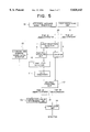
- FIGS. 2(A-D) are a waveform diagram showing how the measuring apparatus of the first embodiment is operated.
- the light-irradiating unit 6 irradiates an electromagnetic wave and at the same time transmits an irradiation start signal to the counter 8 which is a counting unit.
- the counter 8, if receiving the irradiation start signal, starts to count up a counter clock.
- the electromagnetic wave, emitted from the light-irradiating unit 6, is reflected by an object of measurement, and the reflected wave is detected by the light-reception detector 7.
- the detected signal causes the counter 8 to stop counting and the discharge unit 9 to start the electric discharge for interpolating a distance that is measured by the counter 8.
- the electric discharge in this embodiment is performed from the time that the reflected wave is received till the count-up time that the counter 8 counts up for the first time (counting has not been started yet).
- the voltage level at the time of the electric discharge stop will be detected by the signal level detector 10 and converted to a digital value by the A/D converter 11.
- the maximum and minimum signal level detector 15 detects and judges whether the voltage level of the discharge unit 9 has reached the minimum signal level (when the voltage level is less than the minimum signal level already detected, stored, and updated). When the voltage level has reached the minimum signal level, the value is stored and updated as the minimum signal level. If, on the other hand, the voltage level is not the minimum signal level, the subsequent processes will be performed with the previous minimum signal level that has already been obtained in the previous measurement. For the maximum signal level, the voltage before the discharging of the discharge unit 9, detected by the maximum and minimum signal level detector 15, is used.
- the distance computing unit 12 interpolates the count value of the counter 8 with the value of the signal level detector 10 obtained from the A/D converter 11 and then computes a distance to an object of measurement.
- the interpolation value can be obtained, for example, by dividing the discharge voltage V obtained in the signal level detector 10 by a predetermined span value between the maximum and minimum signals.
- the correction-value determining unit 13a computes a correction value for correcting the distance obtained by the aforementioned distance computing unit 12 by using the maximum and minimum signal levels obtained by the maximum and minimum signal level detector 15. With the correction value obtained in the correction-value determining unit 13a, the correction unit 14 performs a correction computation of the measured distance computed by the distance computing unit 12.
- the correction computation can be performed, for example, by dividing the predetermined span value used in the interpolation of the distance computing unit 12 by the distance between the maximum and minimum signal levels actually obtained in the maximum and minimum signal level detector 15 and then by multiplying the interpolation value obtained in the distance computing unit 12 by the value obtained in the division.
- a computing method such as this is merely shown as an example and therefore it is apparent to those having skill in the art that various kinds of distance computing methods can be performed by using the value of the counter 8, the value of the signal level detector 10, and the value of the maximum and minimum signal level detector 15.
- the aforementioned distance computation and correction computation will be performed in the following distance computation equation by changing "MAX" and "MIN" as occasion demands.
- R is the distance to an object of measurement (m)
- C is the count of the counter
- MAX is the maximum signal level
- MIN is the minimum signal level
- ⁇ V is the voltage value of the discharge circuit.
- the minimum signal level of the discharge unit corresponds to the voltage value of the discharge unit 9 after discharging electricity over one clock of a pulse train.
- the minimum signal level for example, each time a smaller discharge voltage is obtained among the discharge voltages (voltages after discharging) of the discharge unit 9 obtained in the measurement of an object after the distance measuring apparatus of the present invention is operated, the value is stored and updated, and the minimum value obtained in this way can be used as a detected value (in the measurement which is performed many times per unit time at a high speed, there is the possibility that the discharge unit discharges electricity over time equivalent to just one clock of a pulse clock, so the value can be used as the minimum signal level).
- the aforementioned predetermined span value may be used as the minimum value.
- the voltage for interpolating a count means having a large count cycle, such as a counter, varied due to an electric noise or the like, a variation in the distance to an object of measurement could be suppressed because the voltage is corrected at every measurement with the maximum and minimum values. This means that, even in the case where in FIGS.
- a triangular wave AD varies as indicated by broken lines (in this embodiment the triangular wave has not been used) and time up to a certain level X varies as shown by L1, L2, and L3, the time can be accurately obtained according to the present invention, that a variation in the measured distance can thus be prevented, and that a measurement of distance can be made with a high degree of reliability.
- a distance to an object of measurement can be accurately measured even in a case where the voltage level of the discharge unit varies due to noise or the like when the discharging of the discharge unit, which is interpolating the counter, is stopped.
- the signal level detector 10 may be constructed such that it measures the voltage of the discharge unit, based on another timing pulse.
- FIG. 3 shows a block diagram of a second embodiment of the present invention, and the same reference numerals as FIG. 1 denote the same parts as FIG. 1 or the corresponding parts of FIG. 1.
- the second embodiment is constructed such that the temperature of a discharge unit 9 is compensated with a reference distance signal having a fixed delay time.
- the second embodiment does not include the maximum and minimum signal level detector 15 shown in the first embodiment. Instead, a reference distance signal generator 16 is used, and the contents of a correction-value determining unit 13b are different from that of the first embodiment.
- switches 20 and 21 are switched in synchronization with each other and are a means for switching the kind of a signal that is supplied to each unit, depending upon whether a distance to an object is being measured actually.
- the operations of the second embodiment differ at the time that a measurement of distance is made and at the time that the distance measurement is not made.
- a counter 8 is started at the time of the delay starting of a reference distance signal generated in the reference distance signal generator 16, and after a predetermined time, the reference distance signal is output to a light-reception detector 7.
- the light-reception detector 7 causes the counter 8 to output a count stop command.
- the electric discharge in the discharge unit 9 is started.
- the subsequent operation from the discharge unit 9 to a distance computing unit 12 is the same as the first embodiment.
- the distance, thus measured with the reference distance signal, should represent a fixed reference distance. Therefore, when the measured distance differs from the reference distance, a correction-distance determining unit 13b determines a correction value, based on the difference.
- the correction-distance determining unit 13b computes a difference between the measured distance based on the aforementioned reference distance signal and the reference distance, and then performs a correction by adding or subtracting the computed difference to or from the subsequent signal level of the discharge unit that is detected by the signal level detector.
- FIGS. 4(A-F) are a timing diagram showing how the second embodiment is operated, and "A" to "AD” denote the same signals as FIG. 2. Also, in FIGS. 4(A-F) are "E” denotes a light-reception detection waveform of the reference distance signal and “F” represents a delayed reference distance signal.
- E denotes a light-reception detection waveform of the reference distance signal
- F represents a delayed reference distance signal.
- the voltage E2 obtained with the reference distance signal at the time of the unreception of light is used in the interpolation computation at the time of the reception of light, and consequently, an accurate interpolation value can be obtained.
- the correction value E2 of the voltage at the end time of the discharge of the discharge unit 9 there is established a non-linear relationship, because the discharge curve is non-linear. Therefore, when E2 is obtained from E1, a numerical table, etc., are used.
- the operation from the light-irradiating unit 6 and the light-reception detector 7 to the distance computing unit 12 is the same as the first embodiment.
- the correction of an actual measurement of a distance to an object can be performed with the distance correcting value, which is determined with the aforementioned reference distance signal at the time when a measurement of distance is not made.
- FIG. 5 shows a block diagram of a distance measuring apparatus of a third embodiment of the present invention, in which a measurement of distance is performed by a combination of the first and second embodiments.
- a correction-value determining unit 13c is a correction-value determining unit where both the determination of the correction value of the first embodiment and the determination of the correction value of the second embodiment are performed.
- the correction-value determining unit 13c detects the maximum and minimum signal levels of a discharge unit 9 by using a maximum and minimum signal level detector 15, and based on the detected values, a correction value is determined.
- the determination of a correction value is performed by using a reference distance signal when a distance is not measured. Then, the distance to an object, obtained by the distance computing unit 12, is corrected with the aforementioned two correction values.
- the correction in the third embodiment is made by superimposing the correction values of the first and second embodiments.
Landscapes
- Engineering & Computer Science (AREA)
- Physics & Mathematics (AREA)
- Computer Networks & Wireless Communication (AREA)
- General Physics & Mathematics (AREA)
- Radar, Positioning & Navigation (AREA)
- Remote Sensing (AREA)
- Electromagnetism (AREA)
- Human Computer Interaction (AREA)
- Mechanical Engineering (AREA)
- Optical Radar Systems And Details Thereof (AREA)
- Radar Systems Or Details Thereof (AREA)
Applications Claiming Priority (2)
| Application Number | Priority Date | Filing Date | Title |
|---|---|---|---|
| JP07195219A JP3138618B2 (ja) | 1995-07-31 | 1995-07-31 | 車両用距離測定装置 |
| JP7-195219 | 1995-07-31 |
Publications (1)
| Publication Number | Publication Date |
|---|---|
| US5828443A true US5828443A (en) | 1998-10-27 |
Family
ID=16337453
Family Applications (1)
| Application Number | Title | Priority Date | Filing Date |
|---|---|---|---|
| US08/607,512 Expired - Fee Related US5828443A (en) | 1995-07-31 | 1996-02-27 | Distance measuring apparatus |
Country Status (4)
| Country | Link |
|---|---|
| US (1) | US5828443A (ja) |
| JP (1) | JP3138618B2 (ja) |
| KR (1) | KR0171260B1 (ja) |
| DE (1) | DE19612437C2 (ja) |
Cited By (5)
| Publication number | Priority date | Publication date | Assignee | Title |
|---|---|---|---|---|
| US6792684B1 (en) * | 1999-10-28 | 2004-09-21 | Diware Oy | Method for determination of stand attributes and a computer program to perform the method |
| US6822681B1 (en) * | 1998-07-02 | 2004-11-23 | Pentax Corporation | Image capturing device for capturing a shape of a measurement subject |
| RU2288449C2 (ru) * | 2004-06-28 | 2006-11-27 | Новосибирский Государственный технический университет (НГТУ) | Лазерный импульсный дальномер |
| US20080079954A1 (en) * | 2005-05-19 | 2008-04-03 | Olympus Corporation | Distance measuring apparatus, distance measuring method, and computer program product |
| US20140063355A1 (en) * | 2012-08-30 | 2014-03-06 | Silicon Touch Technology Inc. | Space positioning method having liquid crystal lens camera |
Families Citing this family (2)
| Publication number | Priority date | Publication date | Assignee | Title |
|---|---|---|---|---|
| KR101981038B1 (ko) * | 2017-08-21 | 2019-05-22 | 주식회사 유진로봇 | 거리 측정 장치, 신호 판별기, 및 이동체 |
| JP6860463B2 (ja) * | 2017-10-03 | 2021-04-14 | 国立大学法人東海国立大学機構 | 繊維配向度の測定方法、繊維配向度測定装置、および繊維配向度測定装置の制御プログラム |
Citations (9)
| Publication number | Priority date | Publication date | Assignee | Title |
|---|---|---|---|---|
| US3618089A (en) * | 1969-01-29 | 1971-11-02 | Moran Instr Corp | Range and time measure system |
| US3630616A (en) * | 1968-03-06 | 1971-12-28 | British Aircraft Corp Ltd | Range finders |
| US3666367A (en) * | 1970-06-01 | 1972-05-30 | Hughes Aircraft Co | Digital range measuring system |
| DE3041272A1 (de) * | 1980-11-03 | 1982-06-03 | Diehl GmbH & Co, 8500 Nürnberg | Elektronischer entfernungsmesser |
| DE3311727A1 (de) * | 1982-05-06 | 1983-11-10 | Wild Heerbrugg AG, 9435 Heerbrugg | Vorrichtung zur laufzeitmessung von elektrischen impulssignalen |
| US4477184A (en) * | 1979-01-19 | 1984-10-16 | Nissan Motor Company, Limited | Obstacle detection system for use in vehicles |
| EP0427969A2 (de) * | 1989-11-14 | 1991-05-22 | Leica AG | Impulslaufzeitmessanordnung |
| US5243553A (en) * | 1991-07-02 | 1993-09-07 | Loral Vought Systems Corporation | Gate array pulse capture device |
| JPH0618666A (ja) * | 1992-06-30 | 1994-01-28 | Mazda Motor Corp | 距離計測装置 |
-
1995
- 1995-07-31 JP JP07195219A patent/JP3138618B2/ja not_active Expired - Fee Related
-
1996
- 1996-02-27 US US08/607,512 patent/US5828443A/en not_active Expired - Fee Related
- 1996-03-28 DE DE19612437A patent/DE19612437C2/de not_active Expired - Fee Related
- 1996-05-27 KR KR1019960017958A patent/KR0171260B1/ko not_active Expired - Fee Related
Patent Citations (9)
| Publication number | Priority date | Publication date | Assignee | Title |
|---|---|---|---|---|
| US3630616A (en) * | 1968-03-06 | 1971-12-28 | British Aircraft Corp Ltd | Range finders |
| US3618089A (en) * | 1969-01-29 | 1971-11-02 | Moran Instr Corp | Range and time measure system |
| US3666367A (en) * | 1970-06-01 | 1972-05-30 | Hughes Aircraft Co | Digital range measuring system |
| US4477184A (en) * | 1979-01-19 | 1984-10-16 | Nissan Motor Company, Limited | Obstacle detection system for use in vehicles |
| DE3041272A1 (de) * | 1980-11-03 | 1982-06-03 | Diehl GmbH & Co, 8500 Nürnberg | Elektronischer entfernungsmesser |
| DE3311727A1 (de) * | 1982-05-06 | 1983-11-10 | Wild Heerbrugg AG, 9435 Heerbrugg | Vorrichtung zur laufzeitmessung von elektrischen impulssignalen |
| EP0427969A2 (de) * | 1989-11-14 | 1991-05-22 | Leica AG | Impulslaufzeitmessanordnung |
| US5243553A (en) * | 1991-07-02 | 1993-09-07 | Loral Vought Systems Corporation | Gate array pulse capture device |
| JPH0618666A (ja) * | 1992-06-30 | 1994-01-28 | Mazda Motor Corp | 距離計測装置 |
Cited By (6)
| Publication number | Priority date | Publication date | Assignee | Title |
|---|---|---|---|---|
| US6822681B1 (en) * | 1998-07-02 | 2004-11-23 | Pentax Corporation | Image capturing device for capturing a shape of a measurement subject |
| US6792684B1 (en) * | 1999-10-28 | 2004-09-21 | Diware Oy | Method for determination of stand attributes and a computer program to perform the method |
| RU2288449C2 (ru) * | 2004-06-28 | 2006-11-27 | Новосибирский Государственный технический университет (НГТУ) | Лазерный импульсный дальномер |
| US20080079954A1 (en) * | 2005-05-19 | 2008-04-03 | Olympus Corporation | Distance measuring apparatus, distance measuring method, and computer program product |
| US7656508B2 (en) * | 2005-05-19 | 2010-02-02 | Olympus Corporation | Distance measuring apparatus, distance measuring method, and computer program product |
| US20140063355A1 (en) * | 2012-08-30 | 2014-03-06 | Silicon Touch Technology Inc. | Space positioning method having liquid crystal lens camera |
Also Published As
| Publication number | Publication date |
|---|---|
| JPH0943351A (ja) | 1997-02-14 |
| JP3138618B2 (ja) | 2001-02-26 |
| KR0171260B1 (ko) | 1999-03-30 |
| DE19612437A1 (de) | 1997-02-06 |
| DE19612437C2 (de) | 2000-09-21 |
| KR970007398A (ko) | 1997-02-21 |
Similar Documents
| Publication | Publication Date | Title |
|---|---|---|
| JP3294726B2 (ja) | レーダ装置 | |
| JP3706305B2 (ja) | 時間遅延の決定および信号シフトの決定 | |
| US20090195770A1 (en) | Method and apparatus for optoelectronic contactless range finding using the transit time principle | |
| JPH06148003A (ja) | 超音波を用いた温度測定装置 | |
| EP2000810A1 (en) | Determination of sine wave period | |
| US5828443A (en) | Distance measuring apparatus | |
| CN113169741A (zh) | 模数转换器 | |
| EP0437417A2 (en) | Method and apparatus for optical distance measurement | |
| US4203112A (en) | Method and system for increasing the distance which can be unambiguously measured by a radar system | |
| CA2516796A1 (en) | An apparatus and method for distance measurement with controlled modulation of emitted pulses | |
| EP3789788B1 (en) | Laser radar device | |
| NL8002888A (nl) | Stelsel voor het meten van de wanddikte van een meetobject. | |
| US5247342A (en) | Light wavelength measuring apparatus including an interference spectroscopic section having a movable portion | |
| US4685075A (en) | Apparatus for measuring propagation time of ultrasonic waves | |
| JP3365196B2 (ja) | レーダ装置 | |
| JP2004226069A (ja) | 測距装置 | |
| JPH0593776A (ja) | 自動車用衝突予防レーダ装置 | |
| JP2003028956A (ja) | 超音波を用いた距離計測装置ならびに位置計測装置およびそのためのプログラム | |
| JP2539749B2 (ja) | レ―ダ―測距装置の距離補正方法 | |
| JPH10153660A (ja) | 距離測定装置 | |
| US11965963B2 (en) | Laser radar | |
| JP2856042B2 (ja) | 車両用レーダ装置 | |
| JPH05312950A (ja) | 距離測定装置および方法 | |
| JPH07198846A (ja) | 距離測定装置 | |
| KR100230461B1 (ko) | 전원 노이즈를 제거한 레이저 거리 측정 장치 및 그 방법 |
Legal Events
| Date | Code | Title | Description |
|---|---|---|---|
| AS | Assignment |
Owner name: MITSUBISHI DENKI KABUSHIKI KAISHA, JAPAN Free format text: ASSIGNMENT OF ASSIGNORS INTEREST;ASSIGNORS:FUJIOKA, HIROSHI;TANAKA, SHOICHI;REEL/FRAME:007996/0565;SIGNING DATES FROM 19960312 TO 19960313 |
|
| FEPP | Fee payment procedure |
Free format text: PAYOR NUMBER ASSIGNED (ORIGINAL EVENT CODE: ASPN); ENTITY STATUS OF PATENT OWNER: LARGE ENTITY |
|
| FPAY | Fee payment |
Year of fee payment: 4 |
|
| FPAY | Fee payment |
Year of fee payment: 8 |
|
| REMI | Maintenance fee reminder mailed | ||
| LAPS | Lapse for failure to pay maintenance fees | ||
| STCH | Information on status: patent discontinuation |
Free format text: PATENT EXPIRED DUE TO NONPAYMENT OF MAINTENANCE FEES UNDER 37 CFR 1.362 |
|
| FP | Lapsed due to failure to pay maintenance fee |
Effective date: 20101027 |