US5813675A - Multibarrier seal - Google Patents
Multibarrier seal Download PDFInfo
- Publication number
- US5813675A US5813675A US08/730,445 US73044596A US5813675A US 5813675 A US5813675 A US 5813675A US 73044596 A US73044596 A US 73044596A US 5813675 A US5813675 A US 5813675A
- Authority
- US
- United States
- Prior art keywords
- lip
- seal
- case
- wall
- fluid barrier
- Prior art date
- Legal status (The legal status is an assumption and is not a legal conclusion. Google has not performed a legal analysis and makes no representation as to the accuracy of the status listed.)
- Expired - Lifetime
Links
Images

Classifications
-
- F—MECHANICAL ENGINEERING; LIGHTING; HEATING; WEAPONS; BLASTING
- F16—ENGINEERING ELEMENTS AND UNITS; GENERAL MEASURES FOR PRODUCING AND MAINTAINING EFFECTIVE FUNCTIONING OF MACHINES OR INSTALLATIONS; THERMAL INSULATION IN GENERAL
- F16C—SHAFTS; FLEXIBLE SHAFTS; ELEMENTS OR CRANKSHAFT MECHANISMS; ROTARY BODIES OTHER THAN GEARING ELEMENTS; BEARINGS
- F16C33/00—Parts of bearings; Special methods for making bearings or parts thereof
- F16C33/72—Sealings
- F16C33/76—Sealings of ball or roller bearings
- F16C33/78—Sealings of ball or roller bearings with a diaphragm, disc, or ring, with or without resilient members
- F16C33/7869—Sealings of ball or roller bearings with a diaphragm, disc, or ring, with or without resilient members mounted with a cylindrical portion to the inner surface of the outer race and having a radial portion extending inward
- F16C33/7879—Sealings of ball or roller bearings with a diaphragm, disc, or ring, with or without resilient members mounted with a cylindrical portion to the inner surface of the outer race and having a radial portion extending inward with a further sealing ring
- F16C33/7883—Sealings of ball or roller bearings with a diaphragm, disc, or ring, with or without resilient members mounted with a cylindrical portion to the inner surface of the outer race and having a radial portion extending inward with a further sealing ring mounted to the inner race and of generally L-shape, the two sealing rings defining a sealing with box-shaped cross-section
-
- F—MECHANICAL ENGINEERING; LIGHTING; HEATING; WEAPONS; BLASTING
- F16—ENGINEERING ELEMENTS AND UNITS; GENERAL MEASURES FOR PRODUCING AND MAINTAINING EFFECTIVE FUNCTIONING OF MACHINES OR INSTALLATIONS; THERMAL INSULATION IN GENERAL
- F16C—SHAFTS; FLEXIBLE SHAFTS; ELEMENTS OR CRANKSHAFT MECHANISMS; ROTARY BODIES OTHER THAN GEARING ELEMENTS; BEARINGS
- F16C33/00—Parts of bearings; Special methods for making bearings or parts thereof
- F16C33/72—Sealings
- F16C33/76—Sealings of ball or roller bearings
- F16C33/78—Sealings of ball or roller bearings with a diaphragm, disc, or ring, with or without resilient members
- F16C33/7869—Sealings of ball or roller bearings with a diaphragm, disc, or ring, with or without resilient members mounted with a cylindrical portion to the inner surface of the outer race and having a radial portion extending inward
- F16C33/7879—Sealings of ball or roller bearings with a diaphragm, disc, or ring, with or without resilient members mounted with a cylindrical portion to the inner surface of the outer race and having a radial portion extending inward with a further sealing ring
-
- F—MECHANICAL ENGINEERING; LIGHTING; HEATING; WEAPONS; BLASTING
- F16—ENGINEERING ELEMENTS AND UNITS; GENERAL MEASURES FOR PRODUCING AND MAINTAINING EFFECTIVE FUNCTIONING OF MACHINES OR INSTALLATIONS; THERMAL INSULATION IN GENERAL
- F16C—SHAFTS; FLEXIBLE SHAFTS; ELEMENTS OR CRANKSHAFT MECHANISMS; ROTARY BODIES OTHER THAN GEARING ELEMENTS; BEARINGS
- F16C33/00—Parts of bearings; Special methods for making bearings or parts thereof
- F16C33/72—Sealings
- F16C33/76—Sealings of ball or roller bearings
- F16C33/78—Sealings of ball or roller bearings with a diaphragm, disc, or ring, with or without resilient members
- F16C33/7886—Sealings of ball or roller bearings with a diaphragm, disc, or ring, with or without resilient members mounted outside the gap between the inner and outer races, e.g. sealing rings mounted to an end face or outer surface of a race
-
- F—MECHANICAL ENGINEERING; LIGHTING; HEATING; WEAPONS; BLASTING
- F16—ENGINEERING ELEMENTS AND UNITS; GENERAL MEASURES FOR PRODUCING AND MAINTAINING EFFECTIVE FUNCTIONING OF MACHINES OR INSTALLATIONS; THERMAL INSULATION IN GENERAL
- F16C—SHAFTS; FLEXIBLE SHAFTS; ELEMENTS OR CRANKSHAFT MECHANISMS; ROTARY BODIES OTHER THAN GEARING ELEMENTS; BEARINGS
- F16C33/00—Parts of bearings; Special methods for making bearings or parts thereof
- F16C33/72—Sealings
- F16C33/76—Sealings of ball or roller bearings
- F16C33/78—Sealings of ball or roller bearings with a diaphragm, disc, or ring, with or without resilient members
- F16C33/7896—Sealings of ball or roller bearings with a diaphragm, disc, or ring, with or without resilient members with two or more discrete sealings arranged in series
-
- F—MECHANICAL ENGINEERING; LIGHTING; HEATING; WEAPONS; BLASTING
- F16—ENGINEERING ELEMENTS AND UNITS; GENERAL MEASURES FOR PRODUCING AND MAINTAINING EFFECTIVE FUNCTIONING OF MACHINES OR INSTALLATIONS; THERMAL INSULATION IN GENERAL
- F16C—SHAFTS; FLEXIBLE SHAFTS; ELEMENTS OR CRANKSHAFT MECHANISMS; ROTARY BODIES OTHER THAN GEARING ELEMENTS; BEARINGS
- F16C33/00—Parts of bearings; Special methods for making bearings or parts thereof
- F16C33/72—Sealings
- F16C33/76—Sealings of ball or roller bearings
- F16C33/80—Labyrinth sealings
- F16C33/805—Labyrinth sealings in addition to other sealings, e.g. dirt guards to protect sealings with sealing lips
-
- F—MECHANICAL ENGINEERING; LIGHTING; HEATING; WEAPONS; BLASTING
- F16—ENGINEERING ELEMENTS AND UNITS; GENERAL MEASURES FOR PRODUCING AND MAINTAINING EFFECTIVE FUNCTIONING OF MACHINES OR INSTALLATIONS; THERMAL INSULATION IN GENERAL
- F16J—PISTONS; CYLINDERS; SEALINGS
- F16J15/00—Sealings
- F16J15/16—Sealings between relatively-moving surfaces
- F16J15/32—Sealings between relatively-moving surfaces with elastic sealings, e.g. O-rings
- F16J15/3248—Sealings between relatively-moving surfaces with elastic sealings, e.g. O-rings provided with casings or supports
- F16J15/3252—Sealings between relatively-moving surfaces with elastic sealings, e.g. O-rings provided with casings or supports with rigid casings or supports
- F16J15/3256—Sealings between relatively-moving surfaces with elastic sealings, e.g. O-rings provided with casings or supports with rigid casings or supports comprising two casing or support elements, one attached to each surface, e.g. cartridge or cassette seals
-
- F—MECHANICAL ENGINEERING; LIGHTING; HEATING; WEAPONS; BLASTING
- F16—ENGINEERING ELEMENTS AND UNITS; GENERAL MEASURES FOR PRODUCING AND MAINTAINING EFFECTIVE FUNCTIONING OF MACHINES OR INSTALLATIONS; THERMAL INSULATION IN GENERAL
- F16C—SHAFTS; FLEXIBLE SHAFTS; ELEMENTS OR CRANKSHAFT MECHANISMS; ROTARY BODIES OTHER THAN GEARING ELEMENTS; BEARINGS
- F16C19/00—Bearings with rolling contact, for exclusively rotary movement
- F16C19/22—Bearings with rolling contact, for exclusively rotary movement with bearing rollers essentially of the same size in one or more circular rows, e.g. needle bearings
- F16C19/34—Bearings with rolling contact, for exclusively rotary movement with bearing rollers essentially of the same size in one or more circular rows, e.g. needle bearings for both radial and axial load
- F16C19/38—Bearings with rolling contact, for exclusively rotary movement with bearing rollers essentially of the same size in one or more circular rows, e.g. needle bearings for both radial and axial load with two or more rows of rollers
- F16C19/383—Bearings with rolling contact, for exclusively rotary movement with bearing rollers essentially of the same size in one or more circular rows, e.g. needle bearings for both radial and axial load with two or more rows of rollers with tapered rollers, i.e. rollers having essentially the shape of a truncated cone
- F16C19/385—Bearings with rolling contact, for exclusively rotary movement with bearing rollers essentially of the same size in one or more circular rows, e.g. needle bearings for both radial and axial load with two or more rows of rollers with tapered rollers, i.e. rollers having essentially the shape of a truncated cone with two rows, i.e. double-row tapered roller bearings
- F16C19/386—Bearings with rolling contact, for exclusively rotary movement with bearing rollers essentially of the same size in one or more circular rows, e.g. needle bearings for both radial and axial load with two or more rows of rollers with tapered rollers, i.e. rollers having essentially the shape of a truncated cone with two rows, i.e. double-row tapered roller bearings in O-arrangement
-
- F—MECHANICAL ENGINEERING; LIGHTING; HEATING; WEAPONS; BLASTING
- F16—ENGINEERING ELEMENTS AND UNITS; GENERAL MEASURES FOR PRODUCING AND MAINTAINING EFFECTIVE FUNCTIONING OF MACHINES OR INSTALLATIONS; THERMAL INSULATION IN GENERAL
- F16C—SHAFTS; FLEXIBLE SHAFTS; ELEMENTS OR CRANKSHAFT MECHANISMS; ROTARY BODIES OTHER THAN GEARING ELEMENTS; BEARINGS
- F16C2326/00—Articles relating to transporting
- F16C2326/01—Parts of vehicles in general
- F16C2326/02—Wheel hubs or castors
Definitions
- This invention relates in general to seals and more particularly to a seal that establishes multiple dynamic barriers between machine components, one of which rotates relative to the other, so as to isolate a region between the components, and also to a bearing that operates with such a seal.
- bearing seals must operate with pressure differentials across them.
- some four wheel drive vehicles rely on partial vacuums to engage the normally nondriven wheels with drive axles, with that engagement occurring in the region of the wheel hubs, which are in turn supported by bearings.
- the seals which isolate the interiors of the bearings from the surrounding environment see the reduced pressure of the partial vacuum.
- only the seal at one end of such a bearing is exposed directly to the region of reduced pressure, but the pressure differential affects the seals at both ends.
- seals operate in hostile environments and must have the capacity to protect the bearing interiors isolated by them from the contaminants in such environments.
- the seals for the bearings at the road wheels of four wheel drive vehicles are representative.
- a seal that establishes only a single dynamic fluid barrier at the end of such a bearing does not provide adequate protection. Multiple dynamic barriers are required.
- the present invention resides in a seal having multiple lips or other configurations which establish dynamic fluid barriers and provide good protection for the interior of a bearing or any other isolated region. Thus it is well-suited for use in hostile environments. It prevents the ingress of contaminants into a bearing or other area isolated by it and has robust lips, each of which has the capacity to hold a partial vacuum.
- the invention also resides in a bearing that operates and has at least one of its ends closed with the seal. The interior of the bearing may exist at a partial vacuum, which the seal holds.
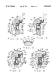
- FIG. 1 is a one-half sectional view taken along the axis of rotation for a bearing fitted with a seal constructed in accordance with and embodying the present invention
- FIG. 2 is an enlarged sectional view of the seal
- FIG. 3 is a fragmentary view of the seal taken along line 3--3 of FIG. 2;
- FIG. 4 is an enlarged sectional view of a modified seal.
- FIG. 5 is an enlarged sectional view of another modified seal fitted with a carrier.
- FIG. 6 is an enlarged view of still another modified seal fitted with a carrier.
- an assembly A for mounting a road wheel of an automotive vehicle on the chassis of the vehicle basically includes a steering knuckle 2 which is attached to the chassis, a drive axle 4 which extends through the knuckle 2, a hub 6 which fits around the axle 4 and is bolted to the road wheel, and an antifriction bearing 8 which is attached to the knuckle 2 and receives the hub 6 and axle 4, enabling them to rotate with minimum friction within the knuckle 2 about an axis x.
- the axle 4 and hub 6 may rotate independently of each other, but may be engaged for operation in unison.
- the assembly A includes clutch 10 for engaging the axle 4 with the hub 6 or disengaging the two, and the clutch 10 is controlled with air pressure.
- an annular chamber 12 lies between the knuckle 2 and the axle 4, and this chamber 12 is in communication with the clutch 10 which is located in another sealed chamber 14 at the other end of the assembly A.
- the clutch 10 sees the reduced pressure and is engaged, but when the chamber 12 is at atmospheric pressure, the clutch 10 is disengaged.
- the clutch 10 does not form part of the present invention, but U.S. Pat. Nos. 4,960,192, 5,085,304 and 5,353,890 show typical clutches.
- the steering knuckle 2 is coupled to the chassis through suitable links and pivots so that it is capable of moving upwardly and downwardly with respect to the chassis and further rotating about a generally vertical axis. It has a flat end face 20 at its outboard end and contains a through bore 22 which opens out of the end face 20.
- the vacuum chamber 12 lies generally within the inboard end of the bore 22 and communicates with a vacuum pump through a vacuum passage 24 that extends obliquely through the knuckle 2.
- the bore 22 is fitted with a rigid seal ring 26 having an inwardly directed flange 28. Actually, the ring 26 is pressed into the end of the bore 22, and as a consequence of the interference fit, a static fluid barrier exists between the knuckle 2 and the ring 26.
- the drive axle 4 has a cylindrical surface 32 which is somewhat smaller than the through bore 22 of the knuckle 2 and a reduced spindle 34 at its outboard end.
- the cylindrical surface 32 extends into the bore 22, but occupies only the very end of the bore 22--the inboard end.
- the spindle 34 extends through the remainder of the bore 22 and beyond, its end being coupled to the clutch 10.
- the spindle 34 projects from a shoulder on the axle 4, and here the axle 4 is fitted with a vacuum seal 40 having a rigid case 42 and an elastomeric seal element 44 bonded to the case 42.
- the case 42 is pressed over the cylindrical surface 32 of the axle 4 and against the shoulder, the interference fit so formed providing a static fluid barrier between the case 42 and the axle 4.
- the seal element 44 has a lip which bears against the flange 28 of the seal ring 26, thereby establishing a dynamic fluid barrier with the seal ring 26.
- the seal 40 and seal ring 26 close one end of the vacuum chamber 12.
- the hub 6 fits around the spindle 34 of the axle 4 and has a reduced cylindrical surface 48 which extends toward the inboard end of the hub 6.
- a nut 50 engages the hub 6.
- the hub 6 has a drive flange 52 which projects outwardly well beyond the cylindrical surface 48 and the through bore 22 in the knuckle 2.
- the hub 6 is fitted with a bearing 54 which receives the spindle 34 of the axle 4 and enables relative rotation to occur between the axle 4 and hub 6.
- the drive flange 52 holds bolts 56 which project axially beyond the outboard face of the flange 52 for attaching a road wheel to the hub 6.
- the drive flange 52 On its inboard face, the drive flange 52 has a relatively smooth sealing surface 58 of annular configuration which lies perpendicular to the axis X and thus is directed radially.
- the sealing surface 58 which is machined and may be ground, faces the outboard end of the bearing 8.
- the clutch 10 is also coupled to the hub 6 at the outboard end of the hub 6.
- the antifriction bearing 8 fits between the knuckle 2 and the hub 6, and enables the hub 6 to rotate within the knuckle 2 with minimal friction.
- the bearing 8 includes an outer ring or race 60, an inner race in the form of two cones 62 and 64, and rolling elements in the form of tapered rollers 66 arranged in two rows between the outer race 60 and two cones 62 and 64.
- the bearing 8 also has cages 68 for maintaining the proper spacing between the rollers 66 in the two rows.
- the outer race 60 has a generally cylindrical outer surface, but intermediate its ends has a flange 70 which projects outwardly from that surface.
- One end of the outer race 60 fits into the through bore 22 of the knuckle 2 such that the flange 70 lies snugly against the flat end face 20 of the knuckle 2.
- the outer race 60 is secured firmly to the knuckle 2 with machine screws 72 which pass through the flange 70 and thread into the knuckle 2.
- the inside corner at the inboard end of the flange 70 contains an O-ring 74 which the screws 72 compress against the end of the knuckle 2 to establish a static fluid barrier between the knuckle 2 and the outer race 60.
- the outer race 60 is of course hollow, and on its inside surface has two raceways 76 which taper downwardly toward the midportion of the race 60.
- the raceways 76 at their large ends open into end bores 78 which in turn open out of the ends of the race 60.
- the outer race 60 is a so-called double cup.
- the two inner races or cones 62 and 64 lie within the outer race 60 and fit over the cylindrical surface 48 of the hub 6 where they are clamped snugly together between the nut 50 and drive flange 52.
- an O-ring 79 is compressed between the outboard cone 64 and the hub 6, establishing a static fluid barrier between the two.
- each cone 62 and 64 includes a tapered raceway 80 which is presented outwardly, a thrust rib 82 at the large end of the raceway 80, and a retaining rib 84 at the small end of its raceway 80.
- the thrust rib 82 has a cylindrical surface 86 that leads out to the back face of the cone 62 or 64.
- the cone 62 resembles a conventional cone, whereas the cone 64 has an extension 88 which projects axially from its retaining rib 84.
- the cone 62 lies within the outer race 60 with its raceway 80 presented opposite the inboard raceway 76 of the outer race 60.
- the cone 64 likewise lies within the outer race 60, but its raceway 80 is opposite to the outboard raceway 76 of the outer race 60.
- the extension 88 on the cone 64 abuts the front face on the retaining rib 84 for the cone 62, thereby establishing a fixed distance between the raceways 80 of the two cones 62 and 64.
- the tapered rollers 66 occupy the annular spaces between the raceways 76 of the outer race 60 and the raceways 80 of the cones 62 and 64. As such, they are arranged in two rows--one around the cone 62 and the other around the cone 64.
- the tapered side faces of the rollers 66 contact and roll along the raceways 76 and 80 when the bearing 8 is in operation, whereas the large diameter end faces of the rollers 66 bear against and move along the thrust ribs 82 of the cones 62 and 64. Indeed, the thrust ribs 82 prevent the rollers 66 from being expelled from the annular space between the raceways 76 and 80. Essentially, pure rolling contact occurs between the side faces of the rollers 66 and the raceways 76 and 80.
- the ends of the bearing 8 are closed by seals 100 and 102 which isolate the interior of the bearing 8, where the rollers 66 and raceways 76 and 80 are located, from the vacuum chamber 12 and from the surrounding environment.
- the seal 100 lies at the inboard end of the bearing 8 where it fits into the end bore 78 and around the thrust rib 82 of the inboard cone 62. As such, it is presented toward the vacuum chamber 12.
- the seal 102 lies at the outboard end of the bearing 8 where it fits into the other end bore 78 and around the thrust rib 82 of the outboard cone 64. It is presented toward the drive flange 52 on the hub 6 and is otherwise exposed to the surrounding environment. Yet by establishing multiple dynamic fluid barriers it prevents contaminants from entering the interior of the bearing 8.
- the inboard seal 100 includes (FIG. 1) an outer case 104 which is pressed into the end bore 78 at the inboard end of the outer race 60, and an inner case 106 which is pressed over the cylindrical surface 86 on the thrust rib 82 for the inboard cone 62.
- the seal 100 also includes an elastomeric seal element 108 which is bonded to the outer case 104 and bears against the inner case 106 to establish a live or dynamic fluid barrier that is capable of preventing the escape of grease from the annular interior of the bearing 8.
- the seal element 108 also contains formations which are presented toward the interior of the bearing 8 and pump grease which encounters the element 108 back toward the rollers 66.
- the seal 100 has another elastomeric seal element 110 bonded to the inner case 106.
- the seal elements 108 and 110 are configured such that they will flex in the presence of a pressure differential between the interior of the bearing 8 and the vacuum chamber 12 to in effect vent the interior of the bearing 8 into the vacuum chamber 12, so that the interior of the bearing 8 will assume essentially the same pressure as the vacuum chamber 12 when the vacuum chamber 12 is evacuated.
- the seal 100 forms the subject of U.S. Pat. No. 5,022,659.
- the outboard seal 102 like the inboard seal 100, includes (FIG. 2) two cases--an outer case 120 which is fitted to the outer race 60 of the bearing 8 and an inner case 122 which is carried by the outboard cone 64 and rotates with it. Both cases 120 and 122 are formed from a generally rigid substance, preferably as metal stampings, and as such they possess a measure of resilience.
- the outer case 120 has two seal elements 124 and 126 which establish live fluid barriers along the inner case 122 and along the sealing surface 58 of the drive flange 52, respectively--fluid barriers having the capacity to hold a partial vacuum in the vacuum chamber 12. Between the two seal elements 124 and 126 lies a liner 128, which actually unites the two seal elements 124 and 126.
- the two seal elements 124 and 126 and the liner 128, which unites them, are molded from an elastomer that is bonded firmly to the outer case 120.
- the inner case 122 carries a seal element 130 which establishes a live fluid barrier with the outer case 120, and this fluid barrier likewise has the capacity to hold a partial vacuum in the vacuum chamber 12.
- the seal element 130 is formed from an elastomer which is bonded to the case 122.
- the outer case 120 has an axial wall 132, an outwardly directed radial wall 134 at one end of the axial wall 132, and an inwardly directed radial wall 136 at the other end of the axial wall 132.
- the axial wall 132 lies almost entirely within the bore 78 at the outboard end of the bearing 8, but is somewhat smaller than the diameter of the bore 78.
- the outwardly directed radial wall 134 lies somewhat beyond the end of the outer race 60, while the inwardly directed radial wall 136 projects inwardly toward the thrust rib 82 of the outboard cone 64 from within the bore 78.
- the outer case 120 fits snugly within the bore 78 of the outer race 60, it being held in place by the liner 128 which exists in a state of compression between axial wall 132 and the surface of the end bore 78. As such it establishes a static fluid barrier between the axial wall 132 and the outer race 60--a barrier that is capable of holding a partial vacuum in the chamber 12.
- Another portion of the liner 128 exists between the outwardly directed radial wall 134 and the end face of the outer race 60 and thus prevents the wall 134 from contacting that face. This portion of the liner 128 exists in a state of compression against the end face of the outer race 60.
- Still another portion of the connecting element 128 lies along the inwardly directed radial wall 136 where it is presented toward the interior of the bearing 8.
- the inner seal element 124 is bonded to the inwardly directed radial wall 136 of the outer case 120 near and along the inner edge of that wall, and it projects inwardly. It includes (FIG. 2) a pumping labyrinth 140 having an end face 142 that extends radially and is presented toward the interior of the bearing 8 to which it is exposed.
- the labyrinth 140 also has a circumferential face 144 which is presented inwardly toward the thrust rib 82 of the outboard cone 64.
- the two faces 142 and 144 meet at a circular edge.
- the labyrinth 140 contains wedge-shaped cavities 146 (FIG. 3) which open out of the end face 142 and the circumferential face 144 and interrupt the edge along which the faces 142 and 144 meet.
- the cavities 146 serve as pumping formations, in that grease which enters them while the bearing 8 is in operation is directed by their oblique surfaces back toward the interior of the bearing 8.
- the inner seal element 124 includes (FIG. 2) a primary lip 148 which is directed obliquely away from the labyrinth 140 and the interior of the bearing 8 so that its back face is normally exposed to air at atmospheric pressure.
- the front face of the element 124 on the other hand, is exposed to the annular interior of the bearing 8.
- the outer seal element 126 for the outer case 120 is bonded to the outwardly directed radial wall 134 of the outer case 120 near and along the end edge for the case 120. It includes (FIG. 2) a tertiary lip 150 which is directed obliquely outwardly from the case 120 and at its end bears against the radial sealing surface 58 on the drive flange 52 of the hub 6.
- the lip 150 establishes a live fluid barrier with the surface 58.
- the back face of the lip 150 is exposed to the exterior environment, so that if a pressure differential exists across the seal element 126, owing to a partial vacuum in the chamber 12, the atmospheric pressure of the surrounding air will urge the lip 150 with greater force against the sealing surface 58 of the drive flange 52.
- the front face of the lip 150 is presented toward the interior of the bearing 8, but not necessarily exposed to it.
- the primary lip 148 of the element 124 and the tertiary lip 150 of the element 126 are independent of each other in the sense that the lips 148 and 150 flex independently.
- flexure of the lip 148 does not affect or disturb the flexure of the lip 150 and vice versa.
- the inner seal case 122 fits around the thrust rib 82 of the outboard cone 64 and as such lies generally within the outer case 120. It includes (FIG. 2) an axial wall 152, a short radially directed wall 154 at that end of the axial wall 152 that is present toward the interior of the bearing 8, and a longer and more substantial radial wall 156 at the other end of the other end of the axial wall 152.
- the two radial walls 154 and 156 project outwardly and lie on opposite sides of the inwardly directed wall 136 of the outer case 120 and likewise on opposite sides of the seal element 124.
- the longer radial wall 156 at its outer end has an axially directed portion 158 which projects toward, but does not contact, the inwardly directed wall 136 of the outer case 120.
- the axial wall 152 of the inner case 122 fits over the cylindrical surface 86 of the thrust rib 82 for the outboard cone 64 with an interference fit which establishes a static fluid barrier between the inner case 122 and the thrust rib 82 of the cone 64. The fluid barrier will maintain a pressure differential created by a partial vacuum in the chamber 12.
- the primary seal lip 148 on the outer case 120 at its free end bears against the axial wall 152 of the inner case 122 near the longer radial wall 156 of the inner case 122 and establishes a live fluid barrier with the inner case 122.
- the lip 148 is molded with its smallest diameter slightly less than the diameter of the axial wall 152 so that the natural bias or resiliency of the elastomer holds the lip 148 snugly in contact with the axial wall 152.
- the fluid barrier will maintain a pressure differential created by a partial vacuum in the vacuum chamber 12.
- the labyrinth 140 In contrast to the primary lip 148, the labyrinth 140 possesses a diameter slightly greater than the diameter of the axial wall 152 for the inner case 122. As a consequence, a gap of perhaps 0.001 to 0.030 inches exists between the circumferential face 144 of the labyrinth 140 and the axial wall 152 of the inner case 122. Even so, grease which migrates along the axial wall 152 when the bearing 8 is in operation encounters the pumping cavities 146 in the labyrinth 140 and, owing to the triangular or wedge-shaped configuration of those cavities, is pumped back to the interior of the bearing 8.
- the seal element 130 for the inner case 122 is bonded almost entirely to the axially directed portion 158 of the longer radial wall 156 for the case 122. It includes a secondary lip 160 which is directed obliquely outwardly and at its free end bears against the axial wall 132 of the outer case 120, establishing a live fluid barrier along that wall. Like the other fluid barriers, the fluid barrier established by the lip 160 will hold a pressure differential created by a partial vacuum in the chamber 12.
- the lip 160 is molded with a diameter slightly greater than the diameter of the axial wall 132, so the resiliency of the elastomer holds it against the wall 132 with some force.
- the inclination of the lip 160 is such that a pressure differential created by a partial vacuum in the chamber 12 and in the space generally enclosed by the two seal cases 120 and 22 will cause atmospheric air, acting on the back face of the lip 160, to urge the lip 160 against the axial wall 132 with even greater force.
- the front face of the lip 160 is of course exposed to the space between the two cases 120 and 122 and beyond that space to the interior of the bearings 8. Being on the inner case 122, the secondary lip 160 flexes independently of the primary lip 148 and the tertiary lip 150 which are on the outer case 120.
- the seal element 130 includes a bumper 162 which lies beyond the end edge of the axially directed portion 158 of the inner case 122, in effect representing an extension of the portion 158.
- the bumper 162 is presented toward the inwardly directed wall 136, with the spacing between the bumper 162 and the wall 136 being less than the spacing between the primary lip 148 and the longer radial wall 156 of the inner case 122.
- the bumper 162 serves as a stop which prevents the primary lip 148 from encountering the longer radial wall 156 of the inner case 122 should the inner case 122 be advanced too far over the thrust rib 82 on which it is mounted.
- the bumper 162 serves to limit the extent that the longer radial wall 156 may deflect toward the inwardly directed wall 136 of the outer case 120 in the presence of a pressure differential across the wall 156. Indeed, it limits the deflection to the elastic range of the metal, so that the inner case 122 does not take on a permanent deformation.
- the hub 6 rotates easily relative to the steering knuckle 2 owing to the bearing 8 which is located between them.
- the seals 100 and 102 at the ends of the bearing 8 retain grease within the interior of the bearing 8, so that the rollers 66 remain adequately lubricated as they roll along the raceways 76 of the outer race 60 and the raceways 80 of the two cones 62 and 64.
- Each of the seal lips 148, 150 and 160 alone possesses enough strength and integrity to hold the partial vacuum in the interior of the bearing 8 and the chamber 12. Initially, the pressure differential at the outboard seal 102 exists across the primary lip 148. The air within the space between the primary and secondary seal lips 148 and 160, which in the space generally enclosed by the two seal cases 120 and 122, is initially at atmospheric pressure, and it urges the primary lip 148 against the axial wall 152 of the inner case 122 with even greater force than the natural resiliency of the elastomer from which the lip 148 is molded.
- the pressure differential will shift to the secondary lip 160.
- the region between that lip 160 and the drive flange 52 for the hub 6 will exist at atmospheric pressure, and the air in that region will bear against the secondary lip 160 and urge it against the axial wall 132 of the outer case 120 with even greater force than that derived from the natural bias of the elastomer from which the lip 160 is molded.
- the tertiary lip 150 will assume that role, and the pressure differential will exist across it.
- the back face of the tertiary lip 150 is exposed to atmospheric air, which will force the lip 150 against the sealing surface 58 of the drive flange 52 with even greater force than that derived from the natural resiliency of the elastomer from which the lip 150 is molded.
- the three live fluid barriers created by the outboard seal 102 make it useful for applications in which no pressure differential exists, yet daunting barriers to the ingress of contaminants are required.
- the bearings for the front wheels of off road vehicles represent one such application.
- the outboard seal 102 owing to the daunting dynamic fluid barriers that it establishes, has utility even when pressure differentials are not created or needed. Thus, it is well-suited for use in bearings exposed to more than the usual amount of dirt and water.
- a modified outboard seal 170 (FIG. 4) is very similar to the outboard seal 102. It has an outer case 120 provided with an axial wall 132 and radial walls 134 and 136. Likewise, it has an inner case 122 provided with an axial wall 152 and a radial wall 156, with the latter having an axially directed portion 158.
- the outer case 120 and inner case 122 for the modified seal 170 are essentially the same as their counterparts for the seal 102, except that their axial walls 132 and 152 are slightly longer, and the same holds true for the axially directed portion 158 on the inner case 122. Consequently, the modified seal 170 is somewhat longer than the seal 102.
- the modified seal 170 also has a secondary lip 160 and bumper 162 and a tertiary lip 150 which corresponds in configuration and location to their counterparts in the seal 102.
- the modified seal 170 has an inner seal element 172 which has a much longer primary lip 174 to establish a more daunting fluid barrier along the axial wall 152 of the inner case 122.
- the inner seal element 172 for the seal 170 in addition to its extended primary lip 174 has a pumping labyrinth 176 which is very similar to the labyrinth 140.
- the lip 174 projects generally axially from the labyrinth 176 and has beveled surfaces 178 which converge to an edge 180 along which the lip 174 bears against the axial wall 152 of the inner case 122.
- the lip 174 has an outwardly opening groove 182 which contains a garter spring 184. While the natural bias of the elastomer from which the lip 174 is molded urges the lip 174 against the axial wall 152 of the inner case 122, the spring 184 supplements the force so exerted, insuring that the edge 180 of the primary lip remains snugly against the axial wall 152.
- Some wheel mounting assemblies do not have a sealing surface 58, much less any generally radially directed surface close enough to the end of the bearing 8 for the tertiary lip 150 of the seal element 126 to contact.
- the vacuum chamber 12 is unnecessary, and the same holds true with regard to the seal ring 26 and vacuum seal 40.
- the inboard end of the bearing 8 is likewise exposed to road contaminants and requires an extra measure of protection.
- the machining operation required to provide a surface smooth enough to effect a fluid barrier with the tertiary lip 150 adds to the overall cost of manufacturing the hub 6.
- Either of the multibarrier seals 102 and 170 or variations of them may be installed in the end of the bearing 8, even when the wheel mounting assembly does not provide a generally radially directed surface against which the tertiary lip 150 can bear. Indeed, the seal may provide its own radially directed surface.
- the multibarrier seal is fitted with a carrier 190 (FIG. 5) in which the inner case 122 is captured.
- the carrier 190 projects both axially and radially from the inner case 122 and indeed extends radially beyond the outer case 120. Yet it lies close enough to the outer case 120 for the tertiary lip 150 to bear against it and establish a fluid barrier.
- the carrier 190 is preferably formed as a metal stamping and as such possesses a measure of resilience. When used with the carrier 190, the multibarrier seal requires only minor modifications, and they reside in the inner case 122.
- the diameter of the inner axial wall 152 for the case 122 is slightly enlarged to accommodate the carrier 190, a portion of which fits between the thrust rib 84 of the bearing cone 62 and the inner wall 152, and the short radial wall 154 is omitted.
- the carrier 190 includes an inner axial wall 192 that fits over the thrust rib 82 at the end of the outboard cone 64, there being an interference fit between the wall 192 and the cylindrical surface 86 of the rib 82.
- the inner axial wall 152 of the inner case 122 in turn fits over the inner axial wall 192 of the carrier 190, again with an interference fit.
- the axial wall 152 needs to be slightly larger to accommodate the wall 192 of the carrier 190.
- the interference fits create static fluid barriers and of course firmly position the carrier 190 and inner case 122 on the cone 64.
- the inner axial wall 192 of the carrier 190 merges into radial walls 194 and 196 which are directed outwardly away from the thrust rib 82 of the cone 64.
- the radial wall 194 lies closest to the rollers 66, and it is presented toward the pumping cavities 146 in the labyrinth 140 for the seal element 124 on the inner case 122.
- the other radial wall 196 lies along and against the radial wall 156 of the inner case 122.
- the radial wall 194, which lies inside the bearing 8, is thinner than the wall 196 which is exposed outside the bearing 8.
- the exposed radial wall 196 of the carrier 190 merges into an axially directed connecting wall 198, which in turn merges into an intermediate radial wall 200 which extends outwardly slightly beyond the axial wall 132 of the outer case 120. Moreover, it lies axially slightly beyond the inner portion of the seal element 126, but not beyond the tertiary lip 150 on the element 126. In this region the intermediate radial wall 200 merges into another connecting wall 202 which is directed axially, still further beyond the end of the bearing 8.
- the outer connecting wall 202 merges into an outer radial wall 204 which extends outwardly past the tertiary lip 150 of the seal element 126, yet lies close enough to the lip 150 to deflect it axially toward the end of the bearing 8.
- the tertiary lip 150 bears against outer radial wall 204 of the carrier 190 and establishes a dynamic fluid barrier with the wall 204.
- the outer radial wall 204 extends past the outwardly presented surface of the outer race 60, that is past the surface from which the flange 70 projects.
- the outer radial wall merges into an oblique return wall 206 that extends generally axially and encircles the end portion of the outer race 60. It serves as a flinger to keep contaminants away from the seal.
- the carrier accommodates either of the seals 102 or 170.
- Other modified seals 210, 212 may be used with or without the carrier 190 (FIGS. 5 & 6).
- the modified seal 210 in lieu of the seal element 130, relies for its intermediate fluid barrier on a labyrinth established by the outer axially directed portion 158 of the inner case 122 and the axial wall 132 of the outer case 120 augmented by the axially directed portion 158 and a rib 214 that projects from the inwardly directed wall 136 of the outer case 120.
- the rib 214 is formed from an elastomer which is bonded to the inwardly directed wall 136.
- the rib 214 and the seal element 124 are joined together with another liner 216, so the rib 214, the seal element 124 and the seal element 126 are united in a single elastomeric molding.
- the axially directed portion 158 of the inner case 122 may be out of round or eccentric with respect to the inner axial wall 152 of the case 122 so as to pump any fluid which enters that labyrinth.
- the other modified seal 212 (FIG. 6) possesses a somewhat simpler inner case 122 in that it omits axially directed portion 158 from the longer radial wall 156 of that case 122. Indeed, the wall 156 simply terminates at an edge which is presented outwardly toward the axial wall 132 of the outer case 120.
- the seal element 130 is bonded to this edge and to the face of the wall 156, and to this end assumes a slightly modified configuration. Yet it has a lip 220 which is directed obliquely toward and bears against axial wall 132 of the outer case 120, with the orientation being such that an elevated pressure beyond the lip 220, that is between it and the tertiary lip 150, will force the lip 220 more tightly against the axial wall 132.
- the other seal element 124 also has a primary lip 224 that differs somewhat from the primary lip 148 of the seal 102 and the primary lip 174 of the seal 170 as well.
- the lip 224 projects generally axially from the inwardly directed wall 136 of the outer case 104 beyond which it has two beveled surfaces 226 and 228 which converge toward an edge 230 that is projected toward and bears against the inner axial wall 152 of the inner case 122.
- the surface 228 also converges with another beveled surface 232, and the intersection of the two creates another edge 234 which projects axially toward and bears against the radial wall 156 of the inner case 122.
- Opening out of the back face of the primary lip 224 is a groove 236 which receives a garter spring 238.
- the groove 236 is configured such that the spring 238 does not bottom out in it, but instead spans the groove 236, bearing against both of its sides. Indeed, on one side of the groove 236, the spring 184 bears against the primary lip 224 in the region generally behind the axially directed edge 234. This has the effect of urging the edge 234 against the radial wall 156 of the inner case 122 and also urging the edge 230 against the inner axial wall 152 of the case 122.
- the primary lip 224 establishes two dynamic fluid barriers with the inner case 122.
- the tertiary lip 150 for any of the seals 102, 170, 210 or 212 may be configured to bear against a generally axially directed wall on the carrier 190, such as the oblique return wall 206.
- the carrier 190 itself may be reconfigured to provide an axially directed wall against which a reconfigured tertiary lip 150 may bear.
- the tertiary lip 150 of any of the seals 102, 170, 210 or 212 may be configured to bear against a radial surface as shown, or an oblique surface, or even an axial surface, the directional reference of course being to the axis X.
Landscapes
- Engineering & Computer Science (AREA)
- General Engineering & Computer Science (AREA)
- Mechanical Engineering (AREA)
- Sealing Of Bearings (AREA)
- Sealing Using Fluids, Sealing Without Contact, And Removal Of Oil (AREA)
Priority Applications (4)
| Application Number | Priority Date | Filing Date | Title |
|---|---|---|---|
| US08/730,445 US5813675A (en) | 1995-10-31 | 1996-10-15 | Multibarrier seal |
| EP96936679A EP0803035A1 (de) | 1995-10-31 | 1996-10-17 | Mehrgitterdichtung |
| PCT/US1996/016710 WO1997016662A1 (en) | 1995-10-31 | 1996-10-17 | Multibarrier seal |
| JP51737597A JP2001510534A (ja) | 1995-10-31 | 1996-10-17 | 多重障壁シール |
Applications Claiming Priority (2)
| Application Number | Priority Date | Filing Date | Title |
|---|---|---|---|
| US55115995A | 1995-10-31 | 1995-10-31 | |
| US08/730,445 US5813675A (en) | 1995-10-31 | 1996-10-15 | Multibarrier seal |
Related Parent Applications (1)
| Application Number | Title | Priority Date | Filing Date |
|---|---|---|---|
| US55115995A Continuation-In-Part | 1995-10-31 | 1995-10-31 |
Publications (1)
| Publication Number | Publication Date |
|---|---|
| US5813675A true US5813675A (en) | 1998-09-29 |
Family
ID=27069668
Family Applications (1)
| Application Number | Title | Priority Date | Filing Date |
|---|---|---|---|
| US08/730,445 Expired - Lifetime US5813675A (en) | 1995-10-31 | 1996-10-15 | Multibarrier seal |
Country Status (4)
| Country | Link |
|---|---|
| US (1) | US5813675A (de) |
| EP (1) | EP0803035A1 (de) |
| JP (1) | JP2001510534A (de) |
| WO (1) | WO1997016662A1 (de) |
Cited By (45)
| Publication number | Priority date | Publication date | Assignee | Title |
|---|---|---|---|---|
| US6050570A (en) * | 1998-01-30 | 2000-04-18 | The Timken Company | Seal with bi-modulus lip |
| WO2001013014A1 (en) * | 1999-08-16 | 2001-02-22 | Roller Bearing Industries, Inc. | Bearing seal |
| US6464399B1 (en) * | 1999-12-27 | 2002-10-15 | The Timken Company | Hub assembly for automotive vehicles |
| EP1096185A3 (de) * | 1999-10-28 | 2003-03-05 | Miele & Cie. GmbH & Co. | Kassettendichtung |
| US20030189297A1 (en) * | 2002-04-04 | 2003-10-09 | Cheng-Hsiung Chen | Sealing device |
| US20040262845A1 (en) * | 2002-01-21 | 2004-12-30 | Shingo Matsui | Seal device |
| DE102005019192A1 (de) * | 2004-05-21 | 2005-12-08 | Aktiebolaget Skf | Dichtvorrichtung für ein Wälzlager |
| US20070081751A1 (en) * | 2005-10-04 | 2007-04-12 | Takayuki Norimatsu | Wheel bearing apparatus |
| US20080073854A1 (en) * | 2006-09-25 | 2008-03-27 | Jtekt Corporation | Sealing structure of wheel supporting device |
| US20080292231A1 (en) * | 2004-06-11 | 2008-11-27 | Hiroki Matsui | Sealing Device |
| US20090127797A1 (en) * | 2005-06-07 | 2009-05-21 | Nok Corporation | Sealing device |
| US20090127796A1 (en) * | 2005-06-07 | 2009-05-21 | Nok Corporation | Sealing device |
| US20090166977A1 (en) * | 2006-07-20 | 2009-07-02 | Carl Freudenberg Kg | Seal |
| US20090220182A1 (en) * | 2008-02-25 | 2009-09-03 | Jtekt Corporation | Bearing apparatus for axle |
| US20090257698A1 (en) * | 2006-10-06 | 2009-10-15 | Ntn Corporation | Wheel Bearing Apparatus For A Vehicle |
| US20100066029A1 (en) * | 2007-04-10 | 2010-03-18 | Nok Corporation | Sealing device |
| US20100259014A1 (en) * | 2007-12-12 | 2010-10-14 | Nok Corporation | Sealing device |
| US20110006485A1 (en) * | 2008-04-25 | 2011-01-13 | Nok Corporation | Sealing device |
| US20110089642A1 (en) * | 2008-06-25 | 2011-04-21 | Uchiyama Manufacturing Corp. | Bearing Seal |
| US20110129176A1 (en) * | 2008-07-08 | 2011-06-02 | Yutaka Koma | Axle bearing system |
| US20110148182A1 (en) * | 2008-08-12 | 2011-06-23 | Schaeffler Technologies Gmbh & Co. Kg | Steering knuckle with pre-sealing |
| JP2012131452A (ja) * | 2010-12-24 | 2012-07-12 | Nsk Ltd | シールリング付車輪支持用転がり軸受ユニット |
| CN103925297A (zh) * | 2013-01-16 | 2014-07-16 | 株式会社捷太格特 | 滚动轴承装置及使用该滚动轴承装置的辊轧机用支承辊 |
| US8844935B2 (en) | 2011-04-13 | 2014-09-30 | Gamesa Innovation & Technology, S.L. | Seal arrangement |
| US20150151573A1 (en) * | 2012-05-11 | 2015-06-04 | Uchiyama Manufacturing Corp. | Sealing structure |
| US20150337961A1 (en) * | 2014-05-26 | 2015-11-26 | Carl Freudenberg Kg | Cassette seal |
| US20150377298A1 (en) * | 2013-02-27 | 2015-12-31 | Schaeffler Technologies AG & Co. KG | Sealing arrangement for axial roller bearings |
| US20160010692A1 (en) * | 2014-07-08 | 2016-01-14 | Jtekt Corporation | Seal and cover |
| DE212014000153U1 (de) | 2013-07-11 | 2016-02-17 | Nsk Ltd. | Radhalterungseinheit mit Wälzlager mit einem Dichtungsring |
| CN105370890A (zh) * | 2014-08-26 | 2016-03-02 | Skf公司 | 低摩擦动态密封件 |
| CN106122287A (zh) * | 2015-02-13 | 2016-11-16 | Kic有限责任公司 | 延伸长度的轴承内圈系统 |
| US9845883B2 (en) * | 2011-06-09 | 2017-12-19 | Federal-Mogul Llc | Shaft seal assembly |
| US20180010680A1 (en) * | 2016-07-08 | 2018-01-11 | Goodrich Actuation Systems Limited | Rotary sealing arrangement |
| EP3447321A1 (de) * | 2017-03-14 | 2019-02-27 | Audi Ag | Mit einem gleichlaufgelenk verbundene radnaben-wälzlageranordnung für ein kraftfahrzeug mit einer dichtungsvorrichtung |
| US20190061421A1 (en) * | 2017-08-31 | 2019-02-28 | Aktiebolaget Skf | Low-friction sealing assembly, system for engagement with a bearing ring, and wheel-hub unit equipped with such a sealing assembly |
| US20190162312A1 (en) * | 2016-05-24 | 2019-05-30 | Ntn Corporation | Bearing sealing device |
| DE102018103109A1 (de) * | 2018-02-13 | 2019-08-14 | Schaeffler Technologies AG & Co. KG | Radlageranordnung mit einer Rotationsachse |
| WO2020068161A1 (en) * | 2018-09-28 | 2020-04-02 | Consolidated Metco, Inc. | Bearing seal with polytetrafluoroethylene thrust bumper |
| US11009075B2 (en) | 2015-09-16 | 2021-05-18 | Ntn Corporation | Bearing device for vehicle wheel |
| US11022178B2 (en) * | 2019-03-13 | 2021-06-01 | Jtekt Corporation | Sealing device and rolling bearing device |
| CN113728184A (zh) * | 2019-03-12 | 2021-11-30 | 美国联合金属制品股份有限公司 | 具有固定塑料晶片的包覆模塑的橡胶衬垫的密封件壳体 |
| US11421738B2 (en) * | 2019-03-18 | 2022-08-23 | Uchiyama Manufacturing Corp. | Bearing sealing device |
| US20240019029A1 (en) * | 2022-07-15 | 2024-01-18 | Uchiyama Manufacturing Corp. | Sealing Device |
| US20240353008A1 (en) * | 2021-09-06 | 2024-10-24 | Schaeffler Technologies AG & Co. KG | Seal structure for in-wheel electric motor drive system, and in-wheel electric motor drive system |
| US12560204B2 (en) * | 2020-10-09 | 2026-02-24 | Aktiebolaget Skf | Sealing device for bearing unit |
Families Citing this family (12)
| Publication number | Priority date | Publication date | Assignee | Title |
|---|---|---|---|---|
| US5722664A (en) * | 1996-09-25 | 1998-03-03 | The Timken Company | Seal with pumping capabilities |
| AU7848998A (en) * | 1996-12-10 | 1998-07-03 | Timken Company, The | Spring-biased seal |
| JP4835045B2 (ja) * | 2005-06-16 | 2011-12-14 | 日本精工株式会社 | 車輪支持用転がり軸受ユニット |
| DE102006047014B4 (de) | 2005-10-04 | 2023-01-19 | Ntn Corp. | Radlagervorrichtung |
| JP5003272B2 (ja) * | 2006-05-22 | 2012-08-15 | 日産自動車株式会社 | 車輪支持構造 |
| US8109674B2 (en) * | 2009-04-27 | 2012-02-07 | Amsted Rail Company, Inc. | Bearing assembly having a dual stage seal |
| FR2971570B1 (fr) * | 2011-02-11 | 2013-04-19 | Ntn Snr Roulements | Palier a roulement presentant une extension annulaire et un dispositif d'etancheite |
| WO2014021179A1 (ja) | 2012-07-30 | 2014-02-06 | Nok株式会社 | 密封装置 |
| ITTO20130980A1 (it) | 2013-11-29 | 2015-05-30 | Skf Ab | Complesso di tenuta a basso attrito, sistema di accoppiamento con un anello di cuscinetto ed unita¿ mozzo ruota equipaggiata con tale complesso di tenuta |
| FR3039865B1 (fr) * | 2015-08-05 | 2018-03-09 | Ntn-Snr Roulements | Assemblage a roulement, essieu de vehicule comprenant un tel assemblage a roulement et procede pour monter un assemblage a roulement |
| JP6704302B2 (ja) * | 2016-06-21 | 2020-06-03 | Ntn株式会社 | 転がり軸受装置 |
| JP7023681B2 (ja) * | 2017-11-24 | 2022-02-22 | 光洋シーリングテクノ株式会社 | ハブユニット用密封装置 |
Citations (34)
| Publication number | Priority date | Publication date | Assignee | Title |
|---|---|---|---|---|
| US3022081A (en) * | 1957-08-01 | 1962-02-20 | Victor Mfg & Gasket Co | Self-contained fluid seal |
| US3510138A (en) * | 1965-10-15 | 1970-05-05 | Federal Mogul Corp | Oil seal with rock shield and wear sleeve |
| US4212557A (en) * | 1978-10-12 | 1980-07-15 | Dana Corporation | Hub clutch |
| US4273460A (en) * | 1978-08-11 | 1981-06-16 | Nissan Motor Company, Limited | Axle construction for four wheel drive vehicles or the like |
| US4285526A (en) * | 1979-09-25 | 1981-08-25 | Stefa Industri Aktiebolag | Sealing device for bearings, especially roll bearings |
| US4293061A (en) * | 1979-07-11 | 1981-10-06 | The Bendix Corporation | Remote controlled hub clutch |
| US4434985A (en) * | 1981-05-13 | 1984-03-06 | Societe Nouvelle De Roulements | Gasket with metal mounting armature rotating between coaxial parts |
| US4516783A (en) * | 1983-02-12 | 1985-05-14 | Nippon Seiko K.K. | Seal assembly with radially overlapping seal means |
| US4625846A (en) * | 1983-10-10 | 1986-12-02 | Avm-Auto Equipamentos Lida | Device for disconnecting the wheels from a vehicle's optional drive |
| US4627512A (en) * | 1985-04-12 | 1986-12-09 | Warn Industries, Inc. | Air actuated clutch for four wheel drive vehicles |
| US4721312A (en) * | 1985-02-16 | 1988-01-26 | Firma Carl Freudenberg | Cassette seal for a shaft |
| EP0286151A2 (de) * | 1987-04-10 | 1988-10-12 | RIV-SKF OFFICINE DI VILLAR PEROSA S.p.A | Dichtung für Lager von Fahrzeugradnaben |
| US4799808A (en) * | 1985-12-19 | 1989-01-24 | The Timken Company | Compact seal |
| EP0321200A2 (de) * | 1987-12-14 | 1989-06-21 | P And C Engineering And Development | Gleitringdichtung und Lagervorrichtung |
| EP0337893A1 (de) * | 1988-04-14 | 1989-10-18 | PROCAL, Société anonyme dite | Kassettendichtung |
| US4928804A (en) * | 1988-02-29 | 1990-05-29 | Aisin Seiki Kabushiki Kaisha | Free wheel hub clutch |
| US4958942A (en) * | 1988-09-26 | 1990-09-25 | Koyo Seiko Co., Ltd. | Oil seal assembly |
| US4960192A (en) * | 1988-01-11 | 1990-10-02 | Tochigifujisangyo Kabushiki Kaisha | Hub clutch |
| US4962936A (en) * | 1987-12-24 | 1990-10-16 | Nok Corporation | Sealing unit |
| US5022659A (en) * | 1988-12-27 | 1991-06-11 | The Timken Company | Seal assembly for antifriction bearings |
| US5024449A (en) * | 1985-12-19 | 1991-06-18 | The Timken Company | Seal assembly for use with an overhang |
| US5037214A (en) * | 1988-02-29 | 1991-08-06 | The Timken Company | Double row tapered roller bearing assembly |
| US5085304A (en) * | 1990-04-30 | 1992-02-04 | Avm Auto-Equipamentos, Ltda. | Automatic free-wheeling hub assembly |
| US5096207A (en) * | 1989-12-02 | 1992-03-17 | Firma Carl Freudenberg | Cartridge seal with dual lipped secondary seal |
| US5129744A (en) * | 1991-06-17 | 1992-07-14 | The Timken Company | Two component bearing seal with bumpers |
| US5141088A (en) * | 1990-05-30 | 1992-08-25 | Tochigifujisangyo Kabushiki Kaisha | Hub clutch device |
| US5148901A (en) * | 1991-03-27 | 1992-09-22 | Tochigifujisangyo Kabushiki Kaisha | Hub clutch for automotive vehicle |
| US5183269A (en) * | 1991-02-06 | 1993-02-02 | Chicago Rawhide Manufacturing Co. | Unitized grit seal with removable thrust bumper |
| EP0532011A1 (de) * | 1991-09-12 | 1993-03-17 | Uchiyama Manufacturing Corp. | Kassettendichtung |
| US5201529A (en) * | 1990-02-16 | 1993-04-13 | Nok Corporation | Sealing device |
| EP0556494A1 (de) * | 1992-02-21 | 1993-08-25 | Gregory H. Petrak | Kassettengleitringdichtung |
| US5261752A (en) * | 1991-09-12 | 1993-11-16 | Nsk Ltd. | Bearing having passive pulser ring |
| US5353890A (en) * | 1992-11-05 | 1994-10-11 | Warn Industries | Locking hub clutch system |
| US5458420A (en) * | 1993-12-10 | 1995-10-17 | The Timken Company | Bearing seal with encoder |
-
1996
- 1996-10-15 US US08/730,445 patent/US5813675A/en not_active Expired - Lifetime
- 1996-10-17 EP EP96936679A patent/EP0803035A1/de not_active Withdrawn
- 1996-10-17 WO PCT/US1996/016710 patent/WO1997016662A1/en not_active Ceased
- 1996-10-17 JP JP51737597A patent/JP2001510534A/ja active Pending
Patent Citations (37)
| Publication number | Priority date | Publication date | Assignee | Title |
|---|---|---|---|---|
| US3022081A (en) * | 1957-08-01 | 1962-02-20 | Victor Mfg & Gasket Co | Self-contained fluid seal |
| US3510138A (en) * | 1965-10-15 | 1970-05-05 | Federal Mogul Corp | Oil seal with rock shield and wear sleeve |
| US4273460A (en) * | 1978-08-11 | 1981-06-16 | Nissan Motor Company, Limited | Axle construction for four wheel drive vehicles or the like |
| US4212557A (en) * | 1978-10-12 | 1980-07-15 | Dana Corporation | Hub clutch |
| US4293061A (en) * | 1979-07-11 | 1981-10-06 | The Bendix Corporation | Remote controlled hub clutch |
| US4285526A (en) * | 1979-09-25 | 1981-08-25 | Stefa Industri Aktiebolag | Sealing device for bearings, especially roll bearings |
| US4434985A (en) * | 1981-05-13 | 1984-03-06 | Societe Nouvelle De Roulements | Gasket with metal mounting armature rotating between coaxial parts |
| US4516783B1 (en) * | 1983-02-12 | 1994-08-02 | Nippon Seiko Kk | Seal assembly with radially overlapping seal |
| US4516783A (en) * | 1983-02-12 | 1985-05-14 | Nippon Seiko K.K. | Seal assembly with radially overlapping seal means |
| US4625846A (en) * | 1983-10-10 | 1986-12-02 | Avm-Auto Equipamentos Lida | Device for disconnecting the wheels from a vehicle's optional drive |
| US4721312A (en) * | 1985-02-16 | 1988-01-26 | Firma Carl Freudenberg | Cassette seal for a shaft |
| US4627512A (en) * | 1985-04-12 | 1986-12-09 | Warn Industries, Inc. | Air actuated clutch for four wheel drive vehicles |
| US4799808A (en) * | 1985-12-19 | 1989-01-24 | The Timken Company | Compact seal |
| US5024449A (en) * | 1985-12-19 | 1991-06-18 | The Timken Company | Seal assembly for use with an overhang |
| EP0286151A2 (de) * | 1987-04-10 | 1988-10-12 | RIV-SKF OFFICINE DI VILLAR PEROSA S.p.A | Dichtung für Lager von Fahrzeugradnaben |
| EP0321200A2 (de) * | 1987-12-14 | 1989-06-21 | P And C Engineering And Development | Gleitringdichtung und Lagervorrichtung |
| US4968044A (en) * | 1987-12-14 | 1990-11-06 | P And C Engineering And Development | Rotary facial seal and bearing assembly |
| US4962936A (en) * | 1987-12-24 | 1990-10-16 | Nok Corporation | Sealing unit |
| US4960192A (en) * | 1988-01-11 | 1990-10-02 | Tochigifujisangyo Kabushiki Kaisha | Hub clutch |
| US4928804A (en) * | 1988-02-29 | 1990-05-29 | Aisin Seiki Kabushiki Kaisha | Free wheel hub clutch |
| US5037214A (en) * | 1988-02-29 | 1991-08-06 | The Timken Company | Double row tapered roller bearing assembly |
| EP0337893A1 (de) * | 1988-04-14 | 1989-10-18 | PROCAL, Société anonyme dite | Kassettendichtung |
| US4958942A (en) * | 1988-09-26 | 1990-09-25 | Koyo Seiko Co., Ltd. | Oil seal assembly |
| US5022659A (en) * | 1988-12-27 | 1991-06-11 | The Timken Company | Seal assembly for antifriction bearings |
| US5096207A (en) * | 1989-12-02 | 1992-03-17 | Firma Carl Freudenberg | Cartridge seal with dual lipped secondary seal |
| US5201529A (en) * | 1990-02-16 | 1993-04-13 | Nok Corporation | Sealing device |
| US5085304A (en) * | 1990-04-30 | 1992-02-04 | Avm Auto-Equipamentos, Ltda. | Automatic free-wheeling hub assembly |
| US5141088A (en) * | 1990-05-30 | 1992-08-25 | Tochigifujisangyo Kabushiki Kaisha | Hub clutch device |
| US5183269A (en) * | 1991-02-06 | 1993-02-02 | Chicago Rawhide Manufacturing Co. | Unitized grit seal with removable thrust bumper |
| US5148901A (en) * | 1991-03-27 | 1992-09-22 | Tochigifujisangyo Kabushiki Kaisha | Hub clutch for automotive vehicle |
| US5129744A (en) * | 1991-06-17 | 1992-07-14 | The Timken Company | Two component bearing seal with bumpers |
| EP0532011A1 (de) * | 1991-09-12 | 1993-03-17 | Uchiyama Manufacturing Corp. | Kassettendichtung |
| US5261752A (en) * | 1991-09-12 | 1993-11-16 | Nsk Ltd. | Bearing having passive pulser ring |
| US5407213A (en) * | 1991-09-12 | 1995-04-18 | Nsk. Ltd. | Pack seal having passive pulser ring |
| EP0556494A1 (de) * | 1992-02-21 | 1993-08-25 | Gregory H. Petrak | Kassettengleitringdichtung |
| US5353890A (en) * | 1992-11-05 | 1994-10-11 | Warn Industries | Locking hub clutch system |
| US5458420A (en) * | 1993-12-10 | 1995-10-17 | The Timken Company | Bearing seal with encoder |
Cited By (73)
| Publication number | Priority date | Publication date | Assignee | Title |
|---|---|---|---|---|
| US6050570A (en) * | 1998-01-30 | 2000-04-18 | The Timken Company | Seal with bi-modulus lip |
| WO2001013014A1 (en) * | 1999-08-16 | 2001-02-22 | Roller Bearing Industries, Inc. | Bearing seal |
| US6485185B1 (en) | 1999-08-16 | 2002-11-26 | Roller Bearing Industries, Inc. | Bearing seal |
| EP1096185A3 (de) * | 1999-10-28 | 2003-03-05 | Miele & Cie. GmbH & Co. | Kassettendichtung |
| US6464399B1 (en) * | 1999-12-27 | 2002-10-15 | The Timken Company | Hub assembly for automotive vehicles |
| US6637943B2 (en) * | 1999-12-27 | 2003-10-28 | The Timkem Company | Hub assembly for automotive vehicles |
| US20040262845A1 (en) * | 2002-01-21 | 2004-12-30 | Shingo Matsui | Seal device |
| US7090221B2 (en) * | 2002-01-21 | 2006-08-15 | Eagle Industry Co., Ltd. | Seal device |
| US20030189297A1 (en) * | 2002-04-04 | 2003-10-09 | Cheng-Hsiung Chen | Sealing device |
| DE102005019192B4 (de) * | 2004-05-21 | 2015-05-13 | Aktiebolaget Skf | Dichtvorrichtung für ein Wälzlager |
| DE102005019192A1 (de) * | 2004-05-21 | 2005-12-08 | Aktiebolaget Skf | Dichtvorrichtung für ein Wälzlager |
| US7674044B2 (en) * | 2004-06-11 | 2010-03-09 | Nok Corporation | Sealing device |
| US20080292231A1 (en) * | 2004-06-11 | 2008-11-27 | Hiroki Matsui | Sealing Device |
| US20090127797A1 (en) * | 2005-06-07 | 2009-05-21 | Nok Corporation | Sealing device |
| US20090127796A1 (en) * | 2005-06-07 | 2009-05-21 | Nok Corporation | Sealing device |
| US20070081751A1 (en) * | 2005-10-04 | 2007-04-12 | Takayuki Norimatsu | Wheel bearing apparatus |
| US7942584B2 (en) * | 2005-10-04 | 2011-05-17 | Ntn Corporation | Wheel bearing apparatus |
| US20090166977A1 (en) * | 2006-07-20 | 2009-07-02 | Carl Freudenberg Kg | Seal |
| US20080073854A1 (en) * | 2006-09-25 | 2008-03-27 | Jtekt Corporation | Sealing structure of wheel supporting device |
| US7793939B2 (en) * | 2006-09-25 | 2010-09-14 | Jtekt Corporation | Sealing structure of wheel supporting device |
| US20090257698A1 (en) * | 2006-10-06 | 2009-10-15 | Ntn Corporation | Wheel Bearing Apparatus For A Vehicle |
| DE112007002329B4 (de) * | 2006-10-06 | 2017-03-23 | Ntn Corp. | Radlagervorrichtung für ein Fahrzeug |
| US8047721B2 (en) | 2006-10-06 | 2011-11-01 | Ntn Corporation | Wheel bearing apparatus for a vehicle |
| US8231129B2 (en) * | 2007-04-10 | 2012-07-31 | Nok Corporation | Sealing device |
| US20100066029A1 (en) * | 2007-04-10 | 2010-03-18 | Nok Corporation | Sealing device |
| US20100259014A1 (en) * | 2007-12-12 | 2010-10-14 | Nok Corporation | Sealing device |
| US8573601B2 (en) * | 2007-12-12 | 2013-11-05 | Nok Corporation | Sealing device |
| US20090220182A1 (en) * | 2008-02-25 | 2009-09-03 | Jtekt Corporation | Bearing apparatus for axle |
| US8167500B2 (en) * | 2008-02-25 | 2012-05-01 | Jtekt Corporation | Bearing apparatus for axle |
| US20110006485A1 (en) * | 2008-04-25 | 2011-01-13 | Nok Corporation | Sealing device |
| US20110089642A1 (en) * | 2008-06-25 | 2011-04-21 | Uchiyama Manufacturing Corp. | Bearing Seal |
| US8770848B2 (en) * | 2008-07-08 | 2014-07-08 | Jtekt Corporation | Axle bearing system |
| US20110129176A1 (en) * | 2008-07-08 | 2011-06-02 | Yutaka Koma | Axle bearing system |
| US8500338B2 (en) * | 2008-08-12 | 2013-08-06 | Schaeffler Technologies AG & Co. KG | Steering knuckle with pre-sealing |
| US20110148182A1 (en) * | 2008-08-12 | 2011-06-23 | Schaeffler Technologies Gmbh & Co. Kg | Steering knuckle with pre-sealing |
| JP2012131452A (ja) * | 2010-12-24 | 2012-07-12 | Nsk Ltd | シールリング付車輪支持用転がり軸受ユニット |
| US8844935B2 (en) | 2011-04-13 | 2014-09-30 | Gamesa Innovation & Technology, S.L. | Seal arrangement |
| US9845883B2 (en) * | 2011-06-09 | 2017-12-19 | Federal-Mogul Llc | Shaft seal assembly |
| US20150151573A1 (en) * | 2012-05-11 | 2015-06-04 | Uchiyama Manufacturing Corp. | Sealing structure |
| CN103925297A (zh) * | 2013-01-16 | 2014-07-16 | 株式会社捷太格特 | 滚动轴承装置及使用该滚动轴承装置的辊轧机用支承辊 |
| CN103925297B (zh) * | 2013-01-16 | 2018-10-26 | 株式会社捷太格特 | 滚动轴承装置及使用该滚动轴承装置的辊轧机用支承辊 |
| US20150377298A1 (en) * | 2013-02-27 | 2015-12-31 | Schaeffler Technologies AG & Co. KG | Sealing arrangement for axial roller bearings |
| US9746032B2 (en) * | 2013-02-27 | 2017-08-29 | Schaeffler Technologies AG & Co. KG | Sealing arrangement for axial roller bearings |
| DE212014000153U1 (de) | 2013-07-11 | 2016-02-17 | Nsk Ltd. | Radhalterungseinheit mit Wälzlager mit einem Dichtungsring |
| US9915347B2 (en) * | 2014-05-26 | 2018-03-13 | Carl Freudenberg Kg | Cassette seal |
| US20150337961A1 (en) * | 2014-05-26 | 2015-11-26 | Carl Freudenberg Kg | Cassette seal |
| US20160010692A1 (en) * | 2014-07-08 | 2016-01-14 | Jtekt Corporation | Seal and cover |
| US20160061266A1 (en) * | 2014-08-26 | 2016-03-03 | Aktiebolaget Skf | Low-friction dynamic seal |
| US9644681B2 (en) * | 2014-08-26 | 2017-05-09 | Aktiebolaget Skf | Low-friction dynamic seal |
| CN105370890A (zh) * | 2014-08-26 | 2016-03-02 | Skf公司 | 低摩擦动态密封件 |
| AU2015204367B2 (en) * | 2014-08-26 | 2018-12-13 | Aktiebolaget Skf | Low-friction dynamic seal |
| CN105370890B (zh) * | 2014-08-26 | 2019-08-30 | Skf公司 | 低摩擦动态密封件 |
| CN106122287A (zh) * | 2015-02-13 | 2016-11-16 | Kic有限责任公司 | 延伸长度的轴承内圈系统 |
| US11009075B2 (en) | 2015-09-16 | 2021-05-18 | Ntn Corporation | Bearing device for vehicle wheel |
| US20190162312A1 (en) * | 2016-05-24 | 2019-05-30 | Ntn Corporation | Bearing sealing device |
| EP3467329A4 (de) * | 2016-05-24 | 2019-06-12 | NTN Corporation | Lagerdichtungsvorrichtung |
| US10648571B2 (en) | 2016-05-24 | 2020-05-12 | Ntn Corporation | Bearing sealing device |
| US20180010680A1 (en) * | 2016-07-08 | 2018-01-11 | Goodrich Actuation Systems Limited | Rotary sealing arrangement |
| US11117421B2 (en) | 2017-03-14 | 2021-09-14 | Audi Ag | Wheel bearing arrangement for a motor vehicle |
| EP3447321A1 (de) * | 2017-03-14 | 2019-02-27 | Audi Ag | Mit einem gleichlaufgelenk verbundene radnaben-wälzlageranordnung für ein kraftfahrzeug mit einer dichtungsvorrichtung |
| US20190061421A1 (en) * | 2017-08-31 | 2019-02-28 | Aktiebolaget Skf | Low-friction sealing assembly, system for engagement with a bearing ring, and wheel-hub unit equipped with such a sealing assembly |
| US10759219B2 (en) * | 2017-08-31 | 2020-09-01 | Aktiebolaget Skf | Low-friction sealing assembly, system for engagement with a bearing ring, and wheel-hub unit equipped with such a sealing assembly |
| DE102018103109A1 (de) * | 2018-02-13 | 2019-08-14 | Schaeffler Technologies AG & Co. KG | Radlageranordnung mit einer Rotationsachse |
| US11835090B2 (en) | 2018-09-28 | 2023-12-05 | Consolidated Metco, Inc. | Bearing seal with polytetrafluoroethylene thrust bumper |
| WO2020068161A1 (en) * | 2018-09-28 | 2020-04-02 | Consolidated Metco, Inc. | Bearing seal with polytetrafluoroethylene thrust bumper |
| US12222003B2 (en) | 2018-09-28 | 2025-02-11 | Consolidated Metco, Inc. | Bearing seal with polytetrafluoroethylene thrust bumper |
| CN113728184A (zh) * | 2019-03-12 | 2021-11-30 | 美国联合金属制品股份有限公司 | 具有固定塑料晶片的包覆模塑的橡胶衬垫的密封件壳体 |
| US11022178B2 (en) * | 2019-03-13 | 2021-06-01 | Jtekt Corporation | Sealing device and rolling bearing device |
| US11421738B2 (en) * | 2019-03-18 | 2022-08-23 | Uchiyama Manufacturing Corp. | Bearing sealing device |
| US12560204B2 (en) * | 2020-10-09 | 2026-02-24 | Aktiebolaget Skf | Sealing device for bearing unit |
| US20240353008A1 (en) * | 2021-09-06 | 2024-10-24 | Schaeffler Technologies AG & Co. KG | Seal structure for in-wheel electric motor drive system, and in-wheel electric motor drive system |
| US20240019029A1 (en) * | 2022-07-15 | 2024-01-18 | Uchiyama Manufacturing Corp. | Sealing Device |
| US12196317B2 (en) * | 2022-07-15 | 2025-01-14 | Uchiyama Manufacturing Corp. | Sealing device |
Also Published As
| Publication number | Publication date |
|---|---|
| JP2001510534A (ja) | 2001-07-31 |
| WO1997016662A1 (en) | 1997-05-09 |
| EP0803035A1 (de) | 1997-10-29 |
Similar Documents
| Publication | Publication Date | Title |
|---|---|---|
| US5813675A (en) | Multibarrier seal | |
| US4448461A (en) | Self-venting seal | |
| US5024449A (en) | Seal assembly for use with an overhang | |
| EP0228847B1 (de) | Dichtung | |
| US4799808A (en) | Compact seal | |
| EP0303359B1 (de) | Dichtung | |
| EP0905394B1 (de) | Betriebsfertiges Lager mit Halter | |
| EP1058792B1 (de) | Lagerabdichtungen | |
| US5553870A (en) | Lip seal separating oil and grease | |
| US6637943B2 (en) | Hub assembly for automotive vehicles | |
| US5201529A (en) | Sealing device | |
| US4533265A (en) | Rolling bearing assemblies fitted with seals | |
| US4516783A (en) | Seal assembly with radially overlapping seal means | |
| EP0301731B1 (de) | Dichtung | |
| US5217137A (en) | Seal for an end cap | |
| GB2124718A (en) | Sealed bearings | |
| US3449029A (en) | Bearing assembly and seal | |
| US4497495A (en) | Unitized wheel bearing seal with multiple lips | |
| US4726696A (en) | Molded rubber seal for bearing and stamping assembly | |
| US4960335A (en) | Unitary enclosure and cover therefor | |
| US3363952A (en) | Dual lip seal | |
| US4545692A (en) | Seal for a rolling bearing unit | |
| KR101273176B1 (ko) | 실 | |
| US3790178A (en) | Bearing seal | |
| US4932796A (en) | Thrust bearing sealing collar assembly |
Legal Events
| Date | Code | Title | Description |
|---|---|---|---|
| AS | Assignment |
Owner name: TIMKEN COMPANY, THE, OHIO Free format text: ASSIGNMENT OF ASSIGNORS INTEREST;ASSIGNOR:OTTO, DENNIS L.;REEL/FRAME:008275/0873 Effective date: 19961010 |
|
| STCF | Information on status: patent grant |
Free format text: PATENTED CASE |
|
| AS | Assignment |
Owner name: MPB CORPORATION, NEW HAMPSHIRE Free format text: ASSIGNMENT OF ASSIGNORS INTEREST;ASSIGNOR:TIMKEN COMPANY, THE;REEL/FRAME:009875/0006 Effective date: 19990318 |
|
| FEPP | Fee payment procedure |
Free format text: PAYOR NUMBER ASSIGNED (ORIGINAL EVENT CODE: ASPN); ENTITY STATUS OF PATENT OWNER: LARGE ENTITY |
|
| FPAY | Fee payment |
Year of fee payment: 4 |
|
| FEPP | Fee payment procedure |
Free format text: PAYER NUMBER DE-ASSIGNED (ORIGINAL EVENT CODE: RMPN); ENTITY STATUS OF PATENT OWNER: LARGE ENTITY Free format text: PAYOR NUMBER ASSIGNED (ORIGINAL EVENT CODE: ASPN); ENTITY STATUS OF PATENT OWNER: LARGE ENTITY |
|
| FPAY | Fee payment |
Year of fee payment: 8 |
|
| FEPP | Fee payment procedure |
Free format text: PAYOR NUMBER ASSIGNED (ORIGINAL EVENT CODE: ASPN); ENTITY STATUS OF PATENT OWNER: LARGE ENTITY Free format text: PAYER NUMBER DE-ASSIGNED (ORIGINAL EVENT CODE: RMPN); ENTITY STATUS OF PATENT OWNER: LARGE ENTITY |
|
| FPAY | Fee payment |
Year of fee payment: 12 |