US5809398A - Channel selective repeater - Google Patents
Channel selective repeater Download PDFInfo
- Publication number
- US5809398A US5809398A US08/648,027 US64802796A US5809398A US 5809398 A US5809398 A US 5809398A US 64802796 A US64802796 A US 64802796A US 5809398 A US5809398 A US 5809398A
- Authority
- US
- United States
- Prior art keywords
- combiner
- selecting means
- signals
- mixer
- input
- Prior art date
- Legal status (The legal status is an assumption and is not a legal conclusion. Google has not performed a legal analysis and makes no representation as to the accuracy of the status listed.)
- Expired - Lifetime
Links
Images


Classifications
-
- H—ELECTRICITY
- H04—ELECTRIC COMMUNICATION TECHNIQUE
- H04B—TRANSMISSION
- H04B7/00—Radio transmission systems, i.e. using radiation field
- H04B7/24—Radio transmission systems, i.e. using radiation field for communication between two or more posts
- H04B7/26—Radio transmission systems, i.e. using radiation field for communication between two or more posts at least one of which is mobile
- H04B7/2603—Arrangements for wireless physical layer control
- H04B7/2606—Arrangements for base station coverage control, e.g. by using relays in tunnels
-
- H—ELECTRICITY
- H04—ELECTRIC COMMUNICATION TECHNIQUE
- H04B—TRANSMISSION
- H04B7/00—Radio transmission systems, i.e. using radiation field
- H04B7/14—Relay systems
- H04B7/15—Active relay systems
- H04B7/155—Ground-based stations
- H04B7/15528—Control of operation parameters of a relay station to exploit the physical medium
- H04B7/15542—Selecting at relay station its transmit and receive resources
-
- H—ELECTRICITY
- H04—ELECTRIC COMMUNICATION TECHNIQUE
- H04W—WIRELESS COMMUNICATION NETWORKS
- H04W16/00—Network planning, e.g. coverage or traffic planning tools; Network deployment, e.g. resource partitioning or cells structures
- H04W16/24—Cell structures
- H04W16/26—Cell enhancers or enhancement, e.g. for tunnels, building shadow
-
- Y—GENERAL TAGGING OF NEW TECHNOLOGICAL DEVELOPMENTS; GENERAL TAGGING OF CROSS-SECTIONAL TECHNOLOGIES SPANNING OVER SEVERAL SECTIONS OF THE IPC; TECHNICAL SUBJECTS COVERED BY FORMER USPC CROSS-REFERENCE ART COLLECTIONS [XRACs] AND DIGESTS
- Y02—TECHNOLOGIES OR APPLICATIONS FOR MITIGATION OR ADAPTATION AGAINST CLIMATE CHANGE
- Y02D—CLIMATE CHANGE MITIGATION TECHNOLOGIES IN INFORMATION AND COMMUNICATION TECHNOLOGIES [ICT], I.E. INFORMATION AND COMMUNICATION TECHNOLOGIES AIMING AT THE REDUCTION OF THEIR OWN ENERGY USE
- Y02D30/00—Reducing energy consumption in communication networks
- Y02D30/70—Reducing energy consumption in communication networks in wireless communication networks
Definitions
- the invention relates to an amplification device, a so-called repeater, for receiving and transmitting RF signals, which are preferably analogically or digitally frequency modulated and are present in cellular telecommunication systems.
- the invention relates to a repeater which improves, through reception, amplification, and, preferably directed, re-transmission of the RF signals, transmitting and receiving performance of a, preferably, mobile terminal and a, preferably, stationary radio unit, in particular a base station, in one or several parts of a cell in at least one cellular telecommunication system.
- Prior art repeaters of the present type normally include two principally similar branches, one branch for down-link communication from the base station to the mobile terminal (the cellular telephone), and one branch for up-link communication from the mobile terminal to the base station.
- Each of these branches include for instance
- a radiator means for incoming and outgoing signals connected to
- a duplex means which has a connection for said outgoing signals and a connection for said incoming signals, the latter being connected to
- a multicoupler which in turn s connected to at least the input of a channel selecting means, which includes
- a filter for channel selecting connected to
- a frequency generator generates a signal to the first and the second mixer
- a combiner connected, via any one of its inputs, to the output of the channel selecting means, the output of said combiner being connected in turn, via a power amplifier, to the connection of the duplex means for outgoing signals in the second branch.
- a prior art repeater of above mentioned type does not have a very high degree of efficiency due to the way in which its power amplifiers are arranged. These power amplifiers amplify all, or at least several, frequency ranges or channels amplified by the repeater. This requires firstly that each power amplifier is capable of providing all of the required output power for its respective branch. Secondly, it is required, as is customary in these applications, that the amplifier does not generate such high levels of mixing frequencies or intermodulation products that the communication is disturbed in the system itself or in other systems. Physically, intermodulation products occur when different frequencies are mixed in a non-linear element. The above mentioned requirements on the power amplifier will not be met by an amplifier with a very high degree of efficiency. A relatively expensive and complicated, so-called, class A amplifier would probably be necessary.
- This repeater which in addition to its amplifier function is arranged to monitor and manipulate the signalling in a cell in a radio communication systems, employs well-known prior art from base stations for controlling and amplifying RF signals in order to meet a frequent and common standard for cellular telecommunication.
- the invention is based on the object to provide a repeater, for a cellular telecommunication system, said repeater having a simpler design, a lower demand for maintenance, and a high degree of efficiency in combination with high power capacity and generation of low levels only of intermodulation products.
- a repeater according to the invention is intended mainly for raising (in a part of a cell) the levels and, possibly, converting the frequencies of the RF signals used in the telecommunication system.
- the repeater according to the invention does not aim at manipulating the RF signals in other ways.
- FIG. 1 shows the fundamental design of a repeater in a first embodiment according to the invention
- FIG. 2 shows the fundamental design of a repeater in a second embodiment according to the invention.
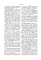
- FIG. 1 shows a block diagram of a repeater in a first embodiment according to the invention.
- This includes a first radiator means 1 for first incoming and first outgoing RF signals between a base station (not shown) and the repeater as well as a second radiator means 2 for second incoming and second outgoing RF signals between the repeater and a subscriber terminal (not shown).
- corresponding incoming and outgoing signals have the same frequency, i.e., the first incoming and the second outgoing signals have the same frequency and vice versa.
- the first radiator means is connected via a first connection to a first duplex means 3, for example a circulator or a duplex filter, which has a second and a third connection as well. Between these connections signals are transferred in such a way that an incoming signal is transferred only to an adjacent connection on the one side, in FIG. 1 the left side.
- the second and the third connections, respectively, of the first duplex means 3 transfer the first incoming and the first outgoing RF signals, respectively.
- the first incoming RF signals are led to an input of a first multicoupler 4 which distributes the RF signals to two or more outputs (four outputs shown in FIG. 1).
- Each of the outputs of the multicoupler 4 is connected to the input of a channel selecting means 6 (only one shown in FIG. 1 in connection with the multicoupler 4), which selects (separates) only one carrier wave (frequency).
- the channel selecting means 6 is also provided with an output.
- the channel selecting means 6 may have several different forms. In the embodiment shown in FIG. 1 it includes, connected to its input, a first mixer 7 connected to a filter 8, preferably a band pass filter that transfers a predetermined frequency band only, which filter 8 is connected to a second mixer 9, which in turn is connected to the output of the channel selecting means 6.
- the first and the second mixers 7, 9 are both connected to a frequency generator 10 arranged outside of the channel selecting means 6, which frequency generator 10 provides a mixing frequency signal thereto.
- the output of the channel selecting means 6 (and corresponding outputs of other channel selecting means situated in the repeater and intended for the first RF signals) is connected to a power amplifier 11 corresponding thereto.
- This may consist of one or several amplifying stages.
- the power amplifier 11 needs to amplify and transfer mainly only the carrier frequency (channel) of the first incoming RF signals, which have been transposed a certain frequency range by the first mixer 7, transferred by the filter 8, and transposed back the same frequency range by the second mixer 9.
- the amplifier 11 may be frequency selective, i.e., attenuating in itself certain frequency bands, and/or further filter means 19, 20 may be arranged between the mixer 9 and the amplifier 11 (and before amplifier 16) for strongly attenuating unwanted frequencies (intermodulation products) generated in the mixer 9.
- filter means 19, 20 may be arranged between the mixer 9 and the amplifier 11 (and before amplifier 16) for strongly attenuating unwanted frequencies (intermodulation products) generated in the mixer 9.
- filter and/or circulator means 18 are preferably arranged after the power amplifier 11 for suppressing of intermodulation products unwanted in the radio communication and/or unwanted interaction between RF signals transferred by different channel selecting means. For example disturbances are hereby avoided between different calls (RF signals) which are transferred simultaneously by the repeater.
- the output of the channel selecting means 6 is connected, via the corresponding amplifier 11, to an input of a preferably passive combiner 12. This is provided with an additional number of inputs and one output, said number of inputs preferably being equal to the number of outputs of the multicoupler 4 and to the number of channel selecting means 6 for the first incoming RF signals.
- the output of the combiner 12 is connected to a third input of a second duplex means 13, the function of which corresponds fully to that of the first duplex means 3.
- the first incoming RF signals are thus transferred to a second radiator means 2, where they turn per definition into second outgoing RF signals to be transferred from the base station to the subscriber terminal (which are not shown in FIG. 1).
- the second incoming and outgoing signals are transferred in the repeater by the second radiator means 2, the second duplex means 13, the second multicoupler 14, second channel selecting means 15 (only one shown in FIG. 1), a second amplifier 16, a second combiner 5, the first duplex means 3, and the first radiator means 1.
- FIG. 2 shows a block diagram of a repeater in a first embodiment according to the invention.
- This includes firstly a first radiator means 201 for first incoming and first outgoing RF signals between a base station (not shown) and the repeater as well as a second radiator means 200 for second incoming and second outgoing RF signals between the repeater and a subscriber terminal (not shown).
- corresponding incoming and outgoing signals have frequencies separated by a predetermined frequency range.
- the first radiator means is connected via a first connection to a first duplex means 203, for example a circulator or a duplex filter, which has a second and a third connection as well. Between these connections signals are transferred in such a way that an incoming signal is transferred only to an adjacent connection on the one side, in FIG. 2 the left side.
- the second and the third connections, respectively, of the first duplex means 203 transfer the first incoming and the first outgoing RF signals, respectively.
- the first incoming RF signals are led to an input of a first multicoupler 204 which distributes the RF signals to two or more outputs (four outputs shown in FIG. 2). At least a first one of the outputs of the multicoupler 204 is connected to the input of a channel selecting means 206 (only one shown in FIG. 2 in connection with the multicoupler 4), which selects (separates) only one carrier wave (frequency). At least a second one of the outputs of the multicoupler 204 is connected to the input of a channel selecting means 225 (only one shown in FIG. 2 in connection with the multicoupler 204), which selects (separates) one frequency band.
- the channel selecting means 206 and the band selecting means 225 are also provided with one output each.
- the channel selecting means 206 may have several different forms. In the embodiment shown in FIG. 2 it includes, connected to its input, a first mixer 207 connected to a filter 208, preferably a band pass filter that transfers a predetermined frequency (channel) only, which filter 208 is connected to a second mixer 209, which in turn is connected to the output of the channel selecting means 206.
- the first and the second mixers 207, 209 are both connected to a frequency generator 210 arranged outside of the channel selecting means 206, which frequency generator 210 provides a mixing frequency signal thereto.
- the mixing frequency signals output to the first and the second mixers 207, 209 may have different frequencies.
- the band selecting means 225 may have several different forms.
- a first mixer 217 is connected to a filter 218, preferably a band pass filter that transfers only a predetermined frequency band (preferably several carrier waves), which filter 218 is connected to a second mixer 219, which in turn is connected to the output of the band selecting means 225.
- its first and second mixers 217, 219 are both connected to a frequency generator 220 arranged outside of the band selecting means 225, which frequency generator 220 provides mixing frequency signals thereto.
- the mixing frequency signals output to the first and the second mixers 217, 219 may have different frequencies.
- the output of the channel selecting means 206 and the band selecting means, respectively, are connected to a first and a second power amplifier 211 and 232, respectively, corresponding thereto. These may consist of one or several amplifying stages.
- the power amplifier 211 needs to amplify and transfer mainly only the carrier frequency (channel) of the first incoming RF signals, which have been transposed a certain frequency range by the first mixer 207, transferred by the filter 208, and transposed again a predetermined frequency range by the second mixer 209.
- the second power amplifier 232 needs to amplify and transfer preferably a full frequency band with several carrier waves (frequencies) includes in the first incoming RF signals.
- the second power amplifier 232 as opposed to the first power amplifier 211, needs to have a broad bandwidth and strictly linear characteristics.
- the amplifier 211 may be frequency selective, i.e., attenuating in itself certain frequency bands, and/or further filter means (not shown) may be arranged between the mixer 209 and the amplifier 211 for strongly attenuating unwanted frequencies (intermodulation products) generated in the mixer 209.
- filter means not shown
- the amplifier 211 is given a relatively simple design, since it needs not to be as strictly linear as an amplifier, which amplifies several different frequencies with the requirement of low internal generation of intermodulation products.
- the amplifier 211 may hereby be designed for lower power consumption.
- filter and/or circulator means 240 are preferably arranged after the power amplifier 211 for suppressing of intermodulation products unwanted in the radio communication and/or of unwanted interaction between RF signals transferred by different channel selecting means. For example disturbances are hereby avoided between different calls (RF signals) which are transferred simultaneously by the repeater.
- corresponding means 242 may be arranged for the second power amplifier 232.
- the output of the channel selecting means 206 and the band selecting means 225, respectively, are connected, via the corresponding first and second amplifiers 211 and 232, respectively, to a first and a second input, respectively, of a preferably passive combiner 212.
- This may be provided with an additional number of inputs and one output, said number of inputs preferably being equal to the number of outputs of the multicoupler 204 and to the number of band/channel selecting means 206 for the first incoming RF signals.
- the output of the combiner 212 is connected to a third input of a second duplex means 213, the function of which corresponds fully to that of the First duplex means 203. Via the first connection of the duplex means 213, the first incoming RF signals are thus transferred to a second radiator means 202, where they turn per definition into second outgoing RF signals to be transferred from the base station to the subscriber terminal (which are not shown in FIG. 2).
- the second incoming and outgoing signals are transferred in the repeater by the second radiator means 202, the second duplex means 213, the second multicoupler 214, second channel selecting means 215 (only one shown in FIG. 2) and second channel selecting means 215 (only one shown in FIG. 2), respectively, further amplifiers 216 and 231, respectively, a second combiner 205, the first duplex means 203, and the first radiator means 201.
Applications Claiming Priority (3)
| Application Number | Priority Date | Filing Date | Title |
|---|---|---|---|
| SE9401640A SE502811C2 (sv) | 1994-05-11 | 1994-05-11 | Repeater |
| SE9401640 | 1994-05-11 | ||
| PCT/SE1995/000517 WO1995031866A1 (en) | 1994-05-11 | 1995-05-10 | Repeater |
Publications (1)
| Publication Number | Publication Date |
|---|---|
| US5809398A true US5809398A (en) | 1998-09-15 |
Family
ID=20393980
Family Applications (1)
| Application Number | Title | Priority Date | Filing Date |
|---|---|---|---|
| US08/648,027 Expired - Lifetime US5809398A (en) | 1994-05-11 | 1995-05-10 | Channel selective repeater |
Country Status (7)
| Country | Link |
|---|---|
| US (1) | US5809398A (sv) |
| EP (1) | EP0772921A1 (sv) |
| CN (1) | CN1150872A (sv) |
| AU (1) | AU693209B2 (sv) |
| CA (1) | CA2189547A1 (sv) |
| SE (1) | SE502811C2 (sv) |
| WO (1) | WO1995031866A1 (sv) |
Cited By (45)
| Publication number | Priority date | Publication date | Assignee | Title |
|---|---|---|---|---|
| US5924031A (en) * | 1997-01-21 | 1999-07-13 | Hughes Electronics Corporation | Interconnective transponder systems and methods |
| US5987304A (en) * | 1996-05-31 | 1999-11-16 | Allgon Ab | Repeater with variable bandwidth |
| US6085075A (en) * | 1997-12-05 | 2000-07-04 | U.S. Philips Corporation | Communication system, a communication device and a frequency synthesizer |
| EP1049251A2 (en) * | 1999-03-31 | 2000-11-02 | Harada Industry Co., Ltd. | Control device |
| US20020054652A1 (en) * | 2000-04-15 | 2002-05-09 | Kim Hyun Wook | Pager having simultaneous multichannel scanning function and data transmitting/receiving method thereof |
| US20020093926A1 (en) * | 2000-12-05 | 2002-07-18 | Kilfoyle Daniel B. | Method and system for a remote downlink transmitter for increasing the capacity of a multiple access interference limited spread-spectrum wireless network |
| US20020123306A1 (en) * | 2001-03-05 | 2002-09-05 | Harvey Masoian | Channelized booster amplifier for cellular communications |
| US6484012B1 (en) * | 1997-08-04 | 2002-11-19 | Wireless Facilities, Inc. | Inter-band communication repeater system |
| US6615021B1 (en) * | 1999-11-02 | 2003-09-02 | Andrew Corporation | Method and apparatus for transmitting radio frequency signals to and from a pager |
| US20030214919A1 (en) * | 2001-09-17 | 2003-11-20 | Kilfoyle Daniel B. | Method and system for a channel selective repeater with capacity enhancement in a spread-spectrum wireless network |
| US6768897B1 (en) * | 1997-09-30 | 2004-07-27 | Nokia Networks Oy | Method of adjusting frequency of cellular radio repeater |
| US20060012463A1 (en) * | 2004-07-15 | 2006-01-19 | Richard Sharpe | Local 2-way paging systems and associated methods |
| US7061891B1 (en) | 2001-02-02 | 2006-06-13 | Science Applications International Corporation | Method and system for a remote downlink transmitter for increasing the capacity and downlink capability of a multiple access interference limited spread-spectrum wireless network |
| US20060205343A1 (en) * | 2005-03-11 | 2006-09-14 | Runyon Donald L | Wireless repeater with feedback suppression features |
| US7123874B1 (en) | 2001-12-10 | 2006-10-17 | Joseph P Brennan | Cellular phone blocker |
| US20070070744A1 (en) * | 2005-09-27 | 2007-03-29 | Macronix International Co., Ltd. | Fast pre-charge circuit and method of providing same for memory devices |
| EP1788740A1 (en) * | 2004-09-29 | 2007-05-23 | Matsushita Electric Industrial Co., Ltd. | Radio communication device and radio communication method |
| US20070149118A1 (en) * | 2005-12-27 | 2007-06-28 | Samsung Electronics Co., Ltd. | Method and system for selecting a relay station in a communication system using a multihop relay scheme |
| US20070232228A1 (en) * | 2006-04-04 | 2007-10-04 | Mckay David L Sr | Wireless repeater with universal server base unit and modular donor antenna options |
| US7299005B1 (en) | 2004-01-07 | 2007-11-20 | Sprint Spectrum L.P. | Radio frequency repeater with automated block/channel selection |
| US20080293360A1 (en) * | 2007-05-22 | 2008-11-27 | Nikolai Maslennikov | On frequency repeater with AGC stability determination |
| US7480485B1 (en) | 2004-01-07 | 2009-01-20 | Sprint Spectrum L.P. | Radio frequency repeater with automated block/channel selection |
| US20090091425A1 (en) * | 2005-07-15 | 2009-04-09 | Richard Sharpe | Pager Solutions For Wireless Device System And Associated Methods |
| US7574230B1 (en) | 2001-05-31 | 2009-08-11 | Sprint Spectrum L.P. | Remote base station with transmit power control |
| US7623866B1 (en) | 2006-07-10 | 2009-11-24 | Sprint Spectrum L.P. | Automatic generation of neighbor lists in a wireless network |
| US7630344B1 (en) | 2001-03-30 | 2009-12-08 | Science Applications International Corporation | Multistage reception of code division multiple access transmissions |
| US20100009625A1 (en) * | 2006-12-04 | 2010-01-14 | Youssef Chami | Base Station Repeater |
| US7848758B1 (en) | 2005-09-27 | 2010-12-07 | Sprint Spectrum L.P. | Dynamic allocation of carrier frequencies in wireless wide area networks |
| US20120164939A1 (en) * | 2009-06-12 | 2012-06-28 | Ntt Docomo, Inc. | Repeater equipment |
| US8320313B1 (en) | 2009-06-19 | 2012-11-27 | Sprint Spectrum L.P. | Method and system for carrier frequency management based on slot contention |
| US8325648B1 (en) | 2009-04-29 | 2012-12-04 | Sprint Spectrum L.P. | Methods and systems for assigning a wireless communication device to a carrier frequency |
| WO2012170044A1 (en) * | 2011-06-07 | 2012-12-13 | Qualcomm Incorporated | Selective carrier amplification in a wireless repeater |
| US8498241B1 (en) | 2009-03-10 | 2013-07-30 | Sprint Spectrum L.P. | Use of macro-network channel-list messages for selection of carriers for low-cost internet base-station frequency-hopping pilot beacons |
| US8798013B1 (en) | 2011-03-25 | 2014-08-05 | Sprint Spectrum L.P. | Method and system for management of data transmission in timeslots |
| US9107148B1 (en) | 2009-11-30 | 2015-08-11 | Sprint Spectrum L.P. | Use of pre-handoff macro-carrier data for prioritization of carriers in femtocell frequency-hopping pilot beacons |
| WO2017214223A1 (en) * | 2016-06-10 | 2017-12-14 | At&T Intellectual Property I, L.P. | Repeater and methods for use therewith |
| US9912027B2 (en) | 2015-07-23 | 2018-03-06 | At&T Intellectual Property I, L.P. | Method and apparatus for exchanging communication signals |
| WO2018057632A1 (en) | 2016-09-23 | 2018-03-29 | Wilson Electronics, Llc | Location based access to selected communication bands |
| US10110295B2 (en) | 2015-06-11 | 2018-10-23 | At&T Intellectual Property I, L.P. | Repeater and methods for use therewith |
| US10142086B2 (en) | 2015-06-11 | 2018-11-27 | At&T Intellectual Property I, L.P. | Repeater and methods for use therewith |
| US10148341B2 (en) * | 2017-02-02 | 2018-12-04 | Wilson Electronics, Llc | Independent band detection for network protection |
| US10424822B2 (en) | 2015-10-14 | 2019-09-24 | Wilson Electronics, Llc | Multi-common port multiband filters |
| US10659142B1 (en) | 2018-12-04 | 2020-05-19 | Wilson Electronics, Llc | Independent band detection for network protection |
| US10811767B2 (en) | 2016-10-21 | 2020-10-20 | At&T Intellectual Property I, L.P. | System and dielectric antenna with convex dielectric radome |
| US20220045700A1 (en) * | 2018-12-21 | 2022-02-10 | Institut Mines Telecom | Method for providing mobile radio connectivity in a confined space by means of an external aerial and associated system |
Families Citing this family (13)
| Publication number | Priority date | Publication date | Assignee | Title |
|---|---|---|---|---|
| SE9602311L (sv) * | 1996-06-12 | 1997-09-01 | Ericsson Telefon Ab L M | Anordning och förfarande vid signalöverföring |
| FI105511B (sv) * | 1996-10-29 | 2000-08-31 | Nokia Networks Oy | Förfarande för att kombinera flera signaler samt basstation |
| FR2770707B1 (fr) * | 1997-10-30 | 2004-01-16 | Telediffusion Fse | Repeteur de signal en modulation de frequence |
| DE19943058A1 (de) * | 1999-09-09 | 2001-03-22 | Bosch Gmbh Robert | Verfahren und System zur Übertragung von Informations-Inhaltsdaten |
| US6697603B1 (en) * | 1999-12-13 | 2004-02-24 | Andrew Corporation | Digital repeater |
| JP2001202168A (ja) * | 2000-01-20 | 2001-07-27 | Sony Computer Entertainment Inc | 中継器 |
| GB2374251A (en) * | 2001-04-04 | 2002-10-09 | Secr Defence | Base station transmitter |
| FR2842372B1 (fr) * | 2002-07-10 | 2004-09-10 | Thomson Licensing Sa | Repeteur de communication radio |
| US7555261B2 (en) | 2003-03-04 | 2009-06-30 | O'neill Frank P | Repeater system for strong signal environments |
| US6993287B2 (en) | 2003-03-04 | 2006-01-31 | Four Bars Clarity, Llc | Repeater system for strong signal environments |
| CN102201799A (zh) * | 2011-05-11 | 2011-09-28 | 深圳市华普特科技有限公司 | 多载频/多频带选频的实现方法及电路 |
| CN106253962A (zh) * | 2016-08-02 | 2016-12-21 | 大连金盛义电子科技有限公司 | 一种无线信号延伸装置 |
| CN109274415B (zh) * | 2018-08-31 | 2021-04-13 | 西安空间无线电技术研究所 | 一种星载转发器通道灵活合成切换系统 |
Citations (6)
| Publication number | Priority date | Publication date | Assignee | Title |
|---|---|---|---|---|
| US4317216A (en) * | 1980-05-09 | 1982-02-23 | Tx Rx Systems, Inc. | Bi-directional filter system for amplifying signals in separate frequency bands |
| US4754495A (en) * | 1985-12-16 | 1988-06-28 | Minori Kawano | Cell enhancer for cellular radio telephone system having bandpass filter arrangement |
| GB2204214A (en) * | 1987-03-24 | 1988-11-02 | Mitsubishi Electric Corp | Bi-directional high-frequency signal booster |
| EP0302455A2 (en) * | 1987-08-03 | 1989-02-08 | Allen Telecom Group, Inc. | Booster |
| JPH05235819A (ja) * | 1992-02-19 | 1993-09-10 | Kokusai Electric Co Ltd | 無線中継装置 |
| EP0274857B1 (en) * | 1986-12-05 | 1994-01-19 | BRITISH TELECOMMUNICATIONS public limited company | Mobile radio systems |
-
1994
- 1994-05-11 SE SE9401640A patent/SE502811C2/sv not_active IP Right Cessation
-
1995
- 1995-05-10 CA CA002189547A patent/CA2189547A1/en not_active Abandoned
- 1995-05-10 EP EP95919715A patent/EP0772921A1/en not_active Withdrawn
- 1995-05-10 AU AU25417/95A patent/AU693209B2/en not_active Ceased
- 1995-05-10 WO PCT/SE1995/000517 patent/WO1995031866A1/en not_active Application Discontinuation
- 1995-05-10 CN CN95193000A patent/CN1150872A/zh active Pending
- 1995-05-10 US US08/648,027 patent/US5809398A/en not_active Expired - Lifetime
Patent Citations (7)
| Publication number | Priority date | Publication date | Assignee | Title |
|---|---|---|---|---|
| US4317216A (en) * | 1980-05-09 | 1982-02-23 | Tx Rx Systems, Inc. | Bi-directional filter system for amplifying signals in separate frequency bands |
| US4754495A (en) * | 1985-12-16 | 1988-06-28 | Minori Kawano | Cell enhancer for cellular radio telephone system having bandpass filter arrangement |
| EP0274857B1 (en) * | 1986-12-05 | 1994-01-19 | BRITISH TELECOMMUNICATIONS public limited company | Mobile radio systems |
| GB2204214A (en) * | 1987-03-24 | 1988-11-02 | Mitsubishi Electric Corp | Bi-directional high-frequency signal booster |
| EP0302455A2 (en) * | 1987-08-03 | 1989-02-08 | Allen Telecom Group, Inc. | Booster |
| US4941200A (en) * | 1987-08-03 | 1990-07-10 | Orion Industries, Inc. | Booster |
| JPH05235819A (ja) * | 1992-02-19 | 1993-09-10 | Kokusai Electric Co Ltd | 無線中継装置 |
Cited By (71)
| Publication number | Priority date | Publication date | Assignee | Title |
|---|---|---|---|---|
| US5987304A (en) * | 1996-05-31 | 1999-11-16 | Allgon Ab | Repeater with variable bandwidth |
| US5924031A (en) * | 1997-01-21 | 1999-07-13 | Hughes Electronics Corporation | Interconnective transponder systems and methods |
| US6684058B1 (en) * | 1997-08-04 | 2004-01-27 | Wireless Facilities, Inc. | Universal repeater for communication systems |
| US6484012B1 (en) * | 1997-08-04 | 2002-11-19 | Wireless Facilities, Inc. | Inter-band communication repeater system |
| US6768897B1 (en) * | 1997-09-30 | 2004-07-27 | Nokia Networks Oy | Method of adjusting frequency of cellular radio repeater |
| US6085075A (en) * | 1997-12-05 | 2000-07-04 | U.S. Philips Corporation | Communication system, a communication device and a frequency synthesizer |
| EP1049251A3 (en) * | 1999-03-31 | 2003-09-03 | Harada Industry Co., Ltd. | Control device |
| EP1049251A2 (en) * | 1999-03-31 | 2000-11-02 | Harada Industry Co., Ltd. | Control device |
| US6615021B1 (en) * | 1999-11-02 | 2003-09-02 | Andrew Corporation | Method and apparatus for transmitting radio frequency signals to and from a pager |
| US20020054652A1 (en) * | 2000-04-15 | 2002-05-09 | Kim Hyun Wook | Pager having simultaneous multichannel scanning function and data transmitting/receiving method thereof |
| US6801121B2 (en) * | 2000-04-15 | 2004-10-05 | Sk Telecom Co., Ltd. | Pager having simultaneous multichannel scanning function and data transmitting/receiving method thereof |
| US20020093926A1 (en) * | 2000-12-05 | 2002-07-18 | Kilfoyle Daniel B. | Method and system for a remote downlink transmitter for increasing the capacity of a multiple access interference limited spread-spectrum wireless network |
| US7016332B2 (en) | 2000-12-05 | 2006-03-21 | Science Applications International Corporation | Method and system for a remote downlink transmitter for increasing the capacity of a multiple access interference limited spread-spectrum wireless network |
| US7535867B1 (en) | 2001-02-02 | 2009-05-19 | Science Applications International Corporation | Method and system for a remote downlink transmitter for increasing the capacity and downlink capability of a multiple access interference limited spread-spectrum wireless network |
| US7061891B1 (en) | 2001-02-02 | 2006-06-13 | Science Applications International Corporation | Method and system for a remote downlink transmitter for increasing the capacity and downlink capability of a multiple access interference limited spread-spectrum wireless network |
| US20020123306A1 (en) * | 2001-03-05 | 2002-09-05 | Harvey Masoian | Channelized booster amplifier for cellular communications |
| US7630344B1 (en) | 2001-03-30 | 2009-12-08 | Science Applications International Corporation | Multistage reception of code division multiple access transmissions |
| US7574230B1 (en) | 2001-05-31 | 2009-08-11 | Sprint Spectrum L.P. | Remote base station with transmit power control |
| US20060077920A1 (en) * | 2001-09-17 | 2006-04-13 | Kilfoyle Daniel B | Method and system for a channel selective repeater with capacity enhancement in a spread-spectrum wireless network |
| US20060077927A1 (en) * | 2001-09-17 | 2006-04-13 | Kilfoyle Daniel B | Method and system for a channel selective repeater with capacity enhancement in a spread-spectrum wireless network |
| US20060083196A1 (en) * | 2001-09-17 | 2006-04-20 | Kilfoyle Daniel B | Method and system for a channel selective repeater with capacity enhancement in a spread-spectrum wireless network |
| US7006461B2 (en) * | 2001-09-17 | 2006-02-28 | Science Applications International Corporation | Method and system for a channel selective repeater with capacity enhancement in a spread-spectrum wireless network |
| US7710913B2 (en) | 2001-09-17 | 2010-05-04 | Science Applications International Corporation | Method and system for a channel selective repeater with capacity enhancement in a spread-spectrum wireless network |
| US7936711B2 (en) | 2001-09-17 | 2011-05-03 | Science Applications International Corporation | Method and system for a channel selective repeater with capacity enhancement in a spread-spectrum wireless network |
| US20030214919A1 (en) * | 2001-09-17 | 2003-11-20 | Kilfoyle Daniel B. | Method and system for a channel selective repeater with capacity enhancement in a spread-spectrum wireless network |
| US7123874B1 (en) | 2001-12-10 | 2006-10-17 | Joseph P Brennan | Cellular phone blocker |
| WO2004032371A1 (en) * | 2002-09-30 | 2004-04-15 | Science Applications International Corporation | Method and system for a channel selective repeater with capacity enhancement in a spread-spectrum wireless network |
| US7480485B1 (en) | 2004-01-07 | 2009-01-20 | Sprint Spectrum L.P. | Radio frequency repeater with automated block/channel selection |
| US7299005B1 (en) | 2004-01-07 | 2007-11-20 | Sprint Spectrum L.P. | Radio frequency repeater with automated block/channel selection |
| US20060012463A1 (en) * | 2004-07-15 | 2006-01-19 | Richard Sharpe | Local 2-way paging systems and associated methods |
| EP1788740A1 (en) * | 2004-09-29 | 2007-05-23 | Matsushita Electric Industrial Co., Ltd. | Radio communication device and radio communication method |
| US20080063097A1 (en) * | 2004-09-29 | 2008-03-13 | Matsushita Electric Industrial Co., Ltd. | Radio Communication Device and Radio Communication Method |
| US8073061B2 (en) | 2004-09-29 | 2011-12-06 | Panasonic Corporation | Radio communication apparatus and radio communication method |
| EP1788740A4 (en) * | 2004-09-29 | 2011-09-21 | Panasonic Corp | RADIO COMMUNICATION DEVICE AND RADIO COMMUNICATION METHOD |
| US20060205341A1 (en) * | 2005-03-11 | 2006-09-14 | Ems Technologies, Inc. | Dual polarization wireless repeater including antenna elements with balanced and quasi-balanced feeds |
| US20060205343A1 (en) * | 2005-03-11 | 2006-09-14 | Runyon Donald L | Wireless repeater with feedback suppression features |
| US20090091425A1 (en) * | 2005-07-15 | 2009-04-09 | Richard Sharpe | Pager Solutions For Wireless Device System And Associated Methods |
| US20070070744A1 (en) * | 2005-09-27 | 2007-03-29 | Macronix International Co., Ltd. | Fast pre-charge circuit and method of providing same for memory devices |
| US7848758B1 (en) | 2005-09-27 | 2010-12-07 | Sprint Spectrum L.P. | Dynamic allocation of carrier frequencies in wireless wide area networks |
| US20070149118A1 (en) * | 2005-12-27 | 2007-06-28 | Samsung Electronics Co., Ltd. | Method and system for selecting a relay station in a communication system using a multihop relay scheme |
| US7853203B2 (en) * | 2005-12-27 | 2010-12-14 | Samsung Electronics Co., Ltd | Method and system for selecting a relay station in a communication system using a multihop relay scheme |
| US20070232228A1 (en) * | 2006-04-04 | 2007-10-04 | Mckay David L Sr | Wireless repeater with universal server base unit and modular donor antenna options |
| US7623866B1 (en) | 2006-07-10 | 2009-11-24 | Sprint Spectrum L.P. | Automatic generation of neighbor lists in a wireless network |
| US20100009625A1 (en) * | 2006-12-04 | 2010-01-14 | Youssef Chami | Base Station Repeater |
| US9014618B2 (en) | 2006-12-04 | 2015-04-21 | Vodafone Group Plc | Base station repeater |
| WO2008147506A1 (en) | 2007-05-22 | 2008-12-04 | Powerwave Technologies, Inc. | On frequency repeater with agc stability determination |
| US20080293360A1 (en) * | 2007-05-22 | 2008-11-27 | Nikolai Maslennikov | On frequency repeater with AGC stability determination |
| US8073387B2 (en) | 2007-05-22 | 2011-12-06 | Powerwave Technologies, Inc. | On frequency repeater with AGC stability determination |
| US8498241B1 (en) | 2009-03-10 | 2013-07-30 | Sprint Spectrum L.P. | Use of macro-network channel-list messages for selection of carriers for low-cost internet base-station frequency-hopping pilot beacons |
| US8325648B1 (en) | 2009-04-29 | 2012-12-04 | Sprint Spectrum L.P. | Methods and systems for assigning a wireless communication device to a carrier frequency |
| US20120164939A1 (en) * | 2009-06-12 | 2012-06-28 | Ntt Docomo, Inc. | Repeater equipment |
| US8320313B1 (en) | 2009-06-19 | 2012-11-27 | Sprint Spectrum L.P. | Method and system for carrier frequency management based on slot contention |
| US9107148B1 (en) | 2009-11-30 | 2015-08-11 | Sprint Spectrum L.P. | Use of pre-handoff macro-carrier data for prioritization of carriers in femtocell frequency-hopping pilot beacons |
| US8798013B1 (en) | 2011-03-25 | 2014-08-05 | Sprint Spectrum L.P. | Method and system for management of data transmission in timeslots |
| US8861429B2 (en) | 2011-06-07 | 2014-10-14 | Qualcomm Incorporated | Selective carrier amplification in a wireless repeater |
| WO2012170044A1 (en) * | 2011-06-07 | 2012-12-13 | Qualcomm Incorporated | Selective carrier amplification in a wireless repeater |
| US10341008B2 (en) | 2015-06-11 | 2019-07-02 | At&T Intellectual Property I, L.P. | Repeater and methods for use therewith |
| US10659212B2 (en) | 2015-06-11 | 2020-05-19 | At&T Intellectual Property I, L.P. | Repeater and methods for use therewith |
| US10110295B2 (en) | 2015-06-11 | 2018-10-23 | At&T Intellectual Property I, L.P. | Repeater and methods for use therewith |
| US10142086B2 (en) | 2015-06-11 | 2018-11-27 | At&T Intellectual Property I, L.P. | Repeater and methods for use therewith |
| US9912027B2 (en) | 2015-07-23 | 2018-03-06 | At&T Intellectual Property I, L.P. | Method and apparatus for exchanging communication signals |
| US10424822B2 (en) | 2015-10-14 | 2019-09-24 | Wilson Electronics, Llc | Multi-common port multiband filters |
| US10847856B2 (en) | 2015-10-14 | 2020-11-24 | Wilson Electronics, Llc | Multi-common port multiband filters |
| WO2017214223A1 (en) * | 2016-06-10 | 2017-12-14 | At&T Intellectual Property I, L.P. | Repeater and methods for use therewith |
| EP3516790A1 (en) * | 2016-09-23 | 2019-07-31 | Wilson Electronics, LLC | Location based access to selected communication bands |
| WO2018057632A1 (en) | 2016-09-23 | 2018-03-29 | Wilson Electronics, Llc | Location based access to selected communication bands |
| EP3516790A4 (en) * | 2016-09-23 | 2020-05-06 | Wilson Electronics, LLC | LOCATION-BASED ACCESS TO SELECTED COMMUNICATION STRIPS |
| US10811767B2 (en) | 2016-10-21 | 2020-10-20 | At&T Intellectual Property I, L.P. | System and dielectric antenna with convex dielectric radome |
| US10148341B2 (en) * | 2017-02-02 | 2018-12-04 | Wilson Electronics, Llc | Independent band detection for network protection |
| US10659142B1 (en) | 2018-12-04 | 2020-05-19 | Wilson Electronics, Llc | Independent band detection for network protection |
| US20220045700A1 (en) * | 2018-12-21 | 2022-02-10 | Institut Mines Telecom | Method for providing mobile radio connectivity in a confined space by means of an external aerial and associated system |
Also Published As
| Publication number | Publication date |
|---|---|
| EP0772921A1 (en) | 1997-05-14 |
| SE502811C2 (sv) | 1996-01-22 |
| AU693209B2 (en) | 1998-06-25 |
| CN1150872A (zh) | 1997-05-28 |
| WO1995031866A1 (en) | 1995-11-23 |
| AU2541795A (en) | 1995-12-05 |
| CA2189547A1 (en) | 1995-11-23 |
| SE9401640L (sv) | 1995-11-12 |
| SE9401640D0 (sv) | 1994-05-11 |
Similar Documents
| Publication | Publication Date | Title |
|---|---|---|
| US5809398A (en) | Channel selective repeater | |
| US5812933A (en) | Duplex RF repeater for personal communications system | |
| US4849963A (en) | Cellular radio telephone enhancement circuit | |
| US6384680B1 (en) | RF amplifier with plural combiners | |
| US6223021B1 (en) | Signal filtering in a transceiver for a wireless telephone system | |
| KR20000074034A (ko) | 케이블 손실 보상이 가능한 초소형 중계기 | |
| EP0468688B1 (en) | Method and apparatus for providing wireless communications between remote locations | |
| US20020123306A1 (en) | Channelized booster amplifier for cellular communications | |
| EP0894372B1 (en) | Channel-selective repeater for mobile telephony | |
| EP0937366B1 (en) | Method of combining several signals, and base station | |
| US20020077150A1 (en) | Base station with antenna, including an amplifier, located at a distance from the base station | |
| JP2981259B2 (ja) | 同一周波無線中継装置 | |
| JP3095126B2 (ja) | 移動無線周波数選択形中継装置 | |
| KR101182035B1 (ko) | 복수안테나를 구비한 원격 기지국 유닛 및 양방향 광 무선네트워크 | |
| WO2024016125A1 (zh) | 一种射频隔离模块及通信系统 | |
| CN1295385A (zh) | 电磁信号的发射/接收装置 | |
| EP1169786A1 (en) | Method and apparatus for improving radio link budget for a cellular base station | |
| JP2000031879A (ja) | 無線中継増幅装置 | |
| JPH10322257A (ja) | 無線中継増幅装置 | |
| JP2942980B2 (ja) | 無線中継装置 | |
| JPH03145829A (ja) | 短距離・多重チャンネル・マイクロ波送信装置 | |
| KR20100112768A (ko) | 티디디 방식 무선 중계장치 | |
| KR20030068334A (ko) | 지상형 중계기 시스템 | |
| KR19980016557A (ko) | 위성통신시스템의 주파수 하향 변환기 | |
| JPH09200106A (ja) | 無線中継増幅装置 |
Legal Events
| Date | Code | Title | Description |
|---|---|---|---|
| AS | Assignment |
Owner name: ALLGON AB, SWEDEN Free format text: ASSIGNMENT OF ASSIGNORS INTEREST;ASSIGNORS:MOBERG, TOMMY;PRAVITZ, ANDERS;REEL/FRAME:009130/0518 Effective date: 19960410 |
|
| STCF | Information on status: patent grant |
Free format text: PATENTED CASE |
|
| CC | Certificate of correction | ||
| FPAY | Fee payment |
Year of fee payment: 4 |
|
| FPAY | Fee payment |
Year of fee payment: 8 |
|
| FPAY | Fee payment |
Year of fee payment: 12 |
|
| AS | Assignment |
Owner name: P-WAVE HOLDINGS, LLC, CALIFORNIA Free format text: SECURITY AGREEMENT;ASSIGNOR:POWERWAVE TECHNOLOGIES, INC.;REEL/FRAME:028939/0381 Effective date: 20120911 |
|
| AS | Assignment |
Owner name: POWERWAVE TECHNOLOGIES, INC., CALIFORNIA Free format text: ASSIGNMENT OF ASSIGNORS INTEREST;ASSIGNOR:POWERWAVE TECHNOLOGIES SWEDEN AB;REEL/FRAME:031925/0237 Effective date: 20130508 Owner name: P-WAVE HOLDINGS, LLC, CALIFORNIA Free format text: ASSIGNMENT OF ASSIGNORS INTEREST;ASSIGNOR:POWERWAVE TECHNOLOGIES, INC.;REEL/FRAME:031925/0252 Effective date: 20130522 |
|
| AS | Assignment |
Owner name: POWERWAVE TECHNOLOGIES S.A.R.L., LUXEMBOURG Free format text: ASSIGNMENT OF ASSIGNORS INTEREST;ASSIGNOR:P-WAVE HOLDINGS, LLC;REEL/FRAME:032366/0432 Effective date: 20140220 |
|
| AS | Assignment |
Owner name: POWERWAVE TECHNOLOGIES SWEDEN AB, SWEDEN Free format text: ASSIGNMENT OF ASSIGNORS INTEREST;ASSIGNOR:POWERWAVE SWEDEN AB;REEL/FRAME:032392/0094 Effective date: 20081103 Owner name: POWERWAVE SWEDEN AB, SWEDEN Free format text: CHANGE OF NAME;ASSIGNOR:ALLGON AB;REEL/FRAME:032422/0253 Effective date: 20041115 |
|
| AS | Assignment |
Owner name: INTEL CORPORATION, CALIFORNIA Free format text: ASSIGNMENT OF ASSIGNORS INTEREST;ASSIGNOR:POWERWAVE TECHNOLOGIES S.A.R.L.;REEL/FRAME:034216/0001 Effective date: 20140827 |
|
| AS | Assignment |
Owner name: POWERWAVE TECHNOLOGIES S.A.R.L., LUXEMBOURG Free format text: CORRECTIVE ASSIGNMENT TO CORRECT THE LIST OF PATENTS ASSIGNED TO REMOVE US PATENT NO. 6617817 PREVIOUSLY RECORDED ON REEL 032366 FRAME 0432. ASSIGNOR(S) HEREBY CONFIRMS THE ASSIGNMENT OF RIGHTS IN THE REMAINING ITEMS TO THE NAMED ASSIGNEE;ASSIGNOR:P-WAVE HOLDINGS, LLC;REEL/FRAME:034429/0889 Effective date: 20140220 |
|
| FEPP | Fee payment procedure |
Free format text: PAYOR NUMBER ASSIGNED (ORIGINAL EVENT CODE: ASPN); ENTITY STATUS OF PATENT OWNER: LARGE ENTITY |