US5764523A - Electronic watt-hour meter - Google Patents
Electronic watt-hour meter Download PDFInfo
- Publication number
- US5764523A US5764523A US08/295,872 US29587294A US5764523A US 5764523 A US5764523 A US 5764523A US 29587294 A US29587294 A US 29587294A US 5764523 A US5764523 A US 5764523A
- Authority
- US
- United States
- Prior art keywords
- value
- quantized
- voltage
- current
- analog
- Prior art date
- Legal status (The legal status is an assumption and is not a legal conclusion. Google has not performed a legal analysis and makes no representation as to the accuracy of the status listed.)
- Expired - Lifetime
Links
Images


Classifications
-
- G—PHYSICS
- G01—MEASURING; TESTING
- G01S—RADIO DIRECTION-FINDING; RADIO NAVIGATION; DETERMINING DISTANCE OR VELOCITY BY USE OF RADIO WAVES; LOCATING OR PRESENCE-DETECTING BY USE OF THE REFLECTION OR RERADIATION OF RADIO WAVES; ANALOGOUS ARRANGEMENTS USING OTHER WAVES
- G01S3/00—Direction-finders for determining the direction from which infrasonic, sonic, ultrasonic, or electromagnetic waves, or particle emission, not having a directional significance, are being received
- G01S3/80—Direction-finders for determining the direction from which infrasonic, sonic, ultrasonic, or electromagnetic waves, or particle emission, not having a directional significance, are being received using ultrasonic, sonic or infrasonic waves
-
- G—PHYSICS
- G01—MEASURING; TESTING
- G01R—MEASURING ELECTRIC VARIABLES; MEASURING MAGNETIC VARIABLES
- G01R21/00—Arrangements for measuring electric power or power factor
- G01R21/133—Arrangements for measuring electric power or power factor by using digital technique
- G01R21/1331—Measuring real or reactive component, measuring apparent energy
-
- G—PHYSICS
- G01—MEASURING; TESTING
- G01R—MEASURING ELECTRIC VARIABLES; MEASURING MAGNETIC VARIABLES
- G01R21/00—Arrangements for measuring electric power or power factor
- G01R21/133—Arrangements for measuring electric power or power factor by using digital technique
Definitions
- the present invention relates to an electronic watt-hour meter for converting analog input signals of a voltage and a current into digital values and processing the digital values.
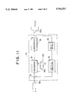
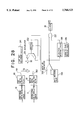
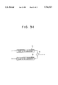
- FIG. 34 shows a block diagram of a circuit for calculating an electric power of a conventional electronic watt-hour meter.
- numeral 71 denotes a first successively comparing type A/D converter into which an analog current signal is input
- numeral 72 denotes a second successively comparing type A/D converter into which an analog voltage signal is input
- numeral 73 denotes a multiplier into which digital data corresponding to a voltage value and a current value from the respective successively comparing type A/D converters 71, 72 is input.
- the conventional electronic watt-hour meter includes the first and second successively comparing type A/D converters 71, 72 as means for converting analog quantities of a voltage and a current into digital values, and an electronic energy w is obtained by calculating these digital outputs by the multiplier 73.
- successively comparing type A/D converters 71, 72 quantize an analog input signal to a digital value in such a manner that an output is discretely increased with respect to the analog input signal by the same resolution, a successively comparing type A/D converter with high resolution is needed to obtain absolute precision for a low level input.
- a successively comparing type A/D converter has a S/N ratio represented by
- a sampling frequency (f s ) of a successively comparing type A/D converter i.e., a so-called over-sampling method.
- a quantized noise is dispersed to a wide bandwidth and the level of spectrum of each frequency component is lowered.
- an over-sampling of 128 times is achieved and a noise level of the signal frequency component is improved by about 21 dB, which is equivalent to an improvement of a resolution of a successively comparing type A/D converter by 3-4 bits.
- a successively comparing type A/D converter having a resolution of 11-12 bits is needed to keep the precision of 0.5% or less of the quantized current value.
- An object of the present invention made to solve the above problems is to provide a high-precision electronic watt-hour meter having a simple circuit arrangement.
- the electronic watt-hour meter comprises first and second analog to digital conversion means for quantizing an AC current and an AC voltage, respectively, first and second moving average processing means for determining a moving average of each of the quantized AC current and the quantized AC voltage, first multiplication means for multiplying the AC current and the AC voltage each subjected to the moving average processing, and cumulation means for cumulating outputs from the multiplication means.
- the electronic watt-hour meter comprises first analog to digital conversion means for quantizing an AC current, second analog to digital conversion means for quantizing an AC voltage, first and second digital low-pass filters for causing the quantized AC current and AC voltage to pass through a low-pass region, respectively, thinning-out means for thinning out the quantized current and the quantized voltage each having been subjected to the low-pass filtration from the sampled value train thereof at a ratio of 1/m (m: a number larger than the number of delay means of the first and second digital low-pass filters), first multiplication means for multiplying an AC current and an AC voltage from the thinning-out means, and cumulation means for cumulating outputs from the multiplication means.
- the electronic watt-hour meter comprises switching means for successively fetching AC currents and AC voltages of respective multiple-element inputs from multiple-input devices from input AC currents and AC voltages of the corresponding elements at a predetermined cycle, first analog to digital conversion means and second analog to digital conversion means for successively quantizing AC currents and AC voltages of the respective multiple-elements from the switching means, first and second digital low-pass filters for causing the quantized AC currents and AC voltages of the respective multiple-elements to successively pass through a low-pass region, thinning-out means for thinning out the quantized currents and the quantized voltages of the respective multiple-elements each having been subjected to the low-pass filtration from the sampled value train thereof at a ratio of 1/m (m: a number larger than the number of delay means of the first and second digital low-pass filters), calculation means for multiplying AC currents and AC voltages which correspond to the multiple-element input and are supplied from the th
- the electronic watt-hour meter comprises switching means for successively switching at a predetermined cycle and outputting respective currents and voltages entered from a first phase, a second phase and a third phase;
- first and second analog to digital conversion means for quantizing AC currents and AC voltages of the respective phases output from the switching means, respectively;
- first and second digital low-pass filters for causing the quantized AC currents and the quantized AC voltages of the respective phases to pass through a low-pass region, respectively;
- thinning-out means for thinning out the quantized AC currents and the quantized AC voltages of the respective phases each having been subjected to the low-pass filtration from the sampled value train thereof at a ratio of 1/m;
- calculation means for multiplying the AC currents of the respective phases from the thinning means by the AC voltages of the respective phases from the thinning means, respectively and determining sums of the multiplication results
- third low-pass filter for causing the outputs of the sums to pass through a low-pass region
- cumulating means for cumulating an output from the third digital low-pass filter; as well as
- an AC current and an AC voltage as analog values are quantized by the first and second analog to digital conversion means, the quantized signals are subjected to a moving average processing by the first and second moving average processing means, signals corresponding to the current and voltage, respectively are multiplied by the multiplier to obtain signals corresponding to electric power and the signals are cumulated to obtain a high precision electric energy.
- an AC current is digitized by the first analog to digital conversion means
- an AC voltage is digitized by the second analog to digital conversion means
- the digitized AC current and AC voltage are caused to pass through a low-pass region by the first and second low-pass filters, respectively.
- the AC current and AC voltage having been passed through the low-pass region are thinned out from the sampled value train thereof by the thinning-out means at a ratio of 1/m (m: a number larger than the number of delay means of the first and second digital low-pass filters).
- the AC current and AC voltage from the thinning-out means are multiplied by the first multiplication means, and outputs from the multiplication means are cumulated by the cumulation means to thereby obtain a high-precision electric energy.
- AC currents and AC voltages of respective multiple-elements are successively fetched at a predetermined cycle from AC currents and AC voltages of the corresponding multiple-elements input by the switching means, the AC currents and AC voltages of the respective elements from the switching means are successively quantized by the first analog to digital conversion means and the second analog to digital conversion means, caused to successively pass through the low-pass region by the first and second digital low-pass filters, and thinned out by the thinning-out means at a ratio of 1/m (m: a number larger than the number of delay means of the first and second digital low-pass filters), AC currents and AC voltages from the thinning-out means which correspond to the multiple-element inputs are multiplied, respectively, sums of the multiplied results are determined by the calculation means and outputs of the sums are cumulated by the cumulation means to obtain an electric energy.
- respective currents and voltages input from a first phase, a second phase and a third phase are successively switched at a predetermined cycle and output by the switching means, and AC currents and AC voltages of the respective phases are quantized by the first and second analog to digital conversion means, respectively.
- the quantized AC currents and AC voltages are caused to pass through the low-pass region by the first and second digital low-pass filters, the quantized AC currents and the quantized AC voltages of the respective phases each having been subjected to the low-pass filtration are thinned out by the thinning-out means from the sampled value train thereof at a ratio of 1/m, the AC currents and the AC voltages of the respective phases from the thinning-out means are multiplied, respectively and the sums of the results of multiplication are determined by the calculation means, and outputs of the sums are caused to pass through the low-pass region by the third low-pass filter and cumulated by the cumulation means.
- the result of cumulation is adjusted by using at least one of the following adjustment means (1), (2), (3), and (4):
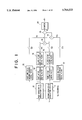
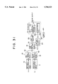
- FIG. 1 shows a block diagram of an electric power calculation unit of an electronic watt-hour meter according to an embodiment 1 of the present invention
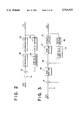
- FIG. 2 shows a block diagram of a primary sigma-delta modulation circuit by way of example
- FIG. 3 shows a block diagram of a secondary sigma-delta modulation circuit by way of example
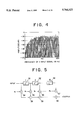
- FIG. 4 is a graph showing a distribution of quantized noise spectrum of the secondary sigma-delta modulation circuit by way of example
- FIG. 5 shows a block diagram of a digital filter constituting a low-pass filter by way of example
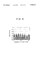
- FIG. 6 is a graph showing a quantized noise spectrum having been subjected to processing by a moving average digital filter
- FIG. 7 shows a block diagram of an electric power calculation unit of an electronic watt-hour meter according to an embodiment 2 of the present invention
- FIG. 8 shows a block diagram of an electric power calculation unit of an electronic watt-hour meter according to an embodiment 3 of the present invention
- FIG. 9 shows a block diagram of an electric power calculation unit of an electronic watt-hour meter according to an embodiment 4 of the present invention.
- FIG. 10 shows a block diagram of an electric power calculation unit of an electronic watt-hour meter according to an embodiment 5 of the present invention
- FIG. 11 shows a block diagram of a primary sigma-delta modulation circuit used for embodiments 5 and 6 of the present invention by way of example;
- FIG. 12 shows a block diagram of an electric power calculation unit of an electronic watt-hour meter according to an embodiment 6 of the present invention
- FIG. 13 shows a block diagram of an electric power calculation unit of an electronic watt-hour meter according to an embodiment 7 of the present invention
- FIG. 14 shows a block diagram of an electric power calculation unit of an electronic watt-hour meter according to an embodiment 8 of the present invention
- FIG. 15 shows a diagram explaining operation of FIG. 14
- FIG. 16 shows a diagram explaining operation of FIG. 14
- FIG. 17 shows a block diagram of an electric power calculation unit of an electronic watt-hour meter according to an embodiment 9 of the present invention.
- FIG. 18 shows a diagram explaining operation of FIG. 17 and FIG. 19;
- FIG. 19 shows a block diagram of an electric power calculation unit of an electronic watt-hour meter according to an embodiment 10 of the present invention.
- FIG. 20 shows a diagram explaining operation of an embodiment 11 of the present invention.
- FIG. 21 shows a block diagram of an electric power calculation unit of an electronic watt-hour meter according to an embodiment 12 of the present invention
- FIG. 22 shows a block diagram of an electric power calculation unit of an electronic watt-hour meter according to an embodiment 13 of the present invention
- FIG. 23 shows a block diagram of an electric power calculation unit of an electronic watt-hour meter according to an embodiment 14 of the present invention
- FIG. 24 shows a block diagram of an electric power calculation unit of an electronic watt-hour meter according to an embodiment 15 of the present invention
- FIG. 25 shows a block diagram of an electric power calculation unit of an electronic watt-hour meter according to an embodiment 16 of the present invention
- FIG. 26 shows a block diagram of an electric power calculation unit of an electronic watt-hour meter according to an embodiment 17 of the present invention
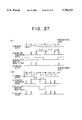
- FIG. 27 shows a diagram explaining operation of FIG. 25 and FIG. 26;
- FIG. 28 shows a block diagram of an electric power calculation unit of an electronic watt-hour meter according to an embodiment 18 of the present invention
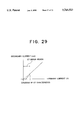
- FIG. 29 is a graph showing output characteristics of a CT
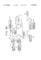
- FIG. 30 shows a block diagram of an electric power calculation unit of an electronic watt-hour meter according to an embodiment 19 of the present invention
- FIG. 31 shows a block diagram of an electric power calculation unit of an electronic watt-hour meter according to an embodiment 20 of the present invention
- FIG. 32 shows a block diagram of an electric power calculation unit of an electronic watt-hour meter according to an embodiment 21 of the present invention
- FIG. 33 is a flowchart showing adjustment operation of FIG. 32.
- FIG. 34 shows a block diagram of an electric power calculation unit of a conventional electronic watt-hour meter.
- numeral 10 denotes a first sigma-delta modulation circuit to which an analog current signal i is input and numeral 11 denotes a second sigma-delta modulation circuit to which an analog voltage signal v is input.
- Numeral 12 denotes a first 16-tap moving average digital filter for determining a moving average at 16 points (hereinafter, referred to as 16 taps) of an output from the first sigma-delta modulation circuit 16.
- Numeral 14 denotes a second 16-tap moving average digital filter connected to the first moving average digital filter 12
- numeral 13 denotes a third 16-tap moving average digital filter for determining a moving average at 16 taps of an output from the second sigma-delta modulation circuit 11
- numeral 15 denotes a fourth 16-tap moving average digital filter connected to the third 16-tap moving average digital filter 13.
- First moving average processing means is composed of the first and second 16-tap moving average digital filters 12, 14 and second moving average processing means is composed of the third and fourth 16-tap moving average digital filters 13, 15.
- Numeral 16 denotes a first one cycle moving average digital filter connected in parallel with the first 16-tap moving average digital filter 12.
- Numeral 17 denotes a second one cycle moving average digital filter connected in parallel with the third 16-tap moving average digital filter 13.
- First and second integration means are composed of the first and second one cycle moving average digital filters 16, 17.
- Numeral 18 denotes a first multiplier to which only one piece of data is input which is thinned out through 1/8 thinning-out means 141, 151 from respective eight pieces of data output from the second and fourth 16-tap moving average digital filters 14, 15.
- Numeral 19 denotes a second multiplier to which only one piece of data is input which is thinned out through 1/8 thinning-out means 161, 171 from respective eight pieces of data output from the first and second one cycle moving average digital filters 16, 17.
- Numeral 20 denotes a subtracter which calculates a difference between an output from the first multiplier 18 and an output from the second multiplier 19 to calculate electric power data w.
- Numeral 30 denotes a counter for integrating the electric power data.
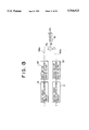
- FIG. 2 shows an internal arrangement of a primary sigma-delta modulation circuit constituting the first and second sigma-delta modulation circuits 10, 11 in FIG. 1.
- an input X(z) is input into an adder 31 in a unit of a sampling frequency (f s ).
- An output from the adder 31 is supplied to an integrator 32 and an output from the integrator 32 is output from a comparator 33 as 1-bit logic data Y(z).
- the output data is fed back to the adder 31 by a one bit D/A converter 34 through delay means 35.
- the above arrangement is referred to as the primary sigma-delta modulation circuit.
- the primary sigma-delta modulation circuit shown in FIG. 2 has an input/output relation expressed by the following formula (3).
- Q(z) is a noise produced by quantization
- a sigma-delta modulated input signal X(z) appears at an output Y(z) as it is and is further added with a noise Q(z) to form an output data.
- a secondary sigma-delta modulation circuit shown in FIG. 3 may constitute the first and second sigma-delta modulation circuits 10, 11 shown in FIG. 1.
- adders 41, 46 and integrators 42, 47 are arranged as two stages, respectively and other components are the same as those shown in the primary sigma-delta modulation circuit shown in FIG. 2.
- the secondary sigma-delta modulation circuit shown in FIG. 3 has an input/output relation expressed by the following formula (4).
- Q(z) is a noise produced by quantization
- An input signal X(z) appears at an output Y(z) as it is similar to the primary sigma-delta modulation circuit also in the formula (4) and is further added with a noise Q(z) to form an output data.
- the formula (3) is different from the formula (4) only in a distribution of a quantized noise caused by the noise (Q(z)) shown in the second term of the respective formulas.
- FIG. 4 shows a distribution of spectrum of a quantized noise caused by a modulating operation of the secondary sigma-delta modulation circuit.
- a low frequency region has a small amount of a quantized noise and a high frequency region has a large amount of quantized noise.
- the secondary sigma-delta modulation circuit of FIG. 3 has a feature that the low frequency region has a smaller amount of a quantized noise.
- outputs from the first and second sigma-delta modulation circuits 10, 11 are formed by adding a quantized noise to input signals.
- the outputs are in the form of 1-bit serial logic data with a sampling rate of 122.88 KHz.
- the first and third 16-tap moving average digital filters 12, 13 shown in FIG. 1 serve as low-pass filters for attenuating a quantized noise in the high frequency region.
- a digital filter is usually composed of delay means 51, 52, 53, multipliers 54, 55, 56, 57 and adders 58, 59, 60.
- the digital filter shown in FIG. 5 includes coefficients a o , a 1 , a 2 , . . .
- the first and second 16-tap moving average digital filters 12, 14 having the arrangement shown in FIG. I can be also realized as a whole by the digital filter shown in FIG. 5 (coefficient a n is not only 1).
- the first and second 16-tap moving average digital filters 12, 14 are expressed as follows.
- the digital filter shown in FIG. 5 which has the coefficient a n of (1, 2, 3, . . . 3, 2, 1) and 31 taps is equivalent with a two-staged moving average digital filter. This is also applied to the third and fourth 16-tap moving average digital filters 13, 15 shown in FIG. 1 in the same way.
- FIG. 6 shows a distribution of a spectrum of a quantized noise of an output having passed through the first and third 16-tap moving average digital filters 12, 13 and further the second and fourth 16-tap moving average digital filters 14, 15.
- Output data having a 8-bit width of the second 16-tap moving average digital filter 14 corresponding to an analog current signal i and output data having a 8-bit width of the fourth 16-tap moving average digital filter 15 corresponding to an analog voltage signal v are used by the first multiplier 18 to calculate an electric power after these outputs are subjected to a thinning-out operation for thinning out one piece of output data from respective eight pieces of output data through the 1/8 thinning-out means 141, 151.
- voltage data V and current data I to be input to the first multiplier 18 are expressed by the following formulas (5) and (6).
- V s is an input signal and V N is a quantized noise of each frequency.
- I s is an input signal and I N is a quantized noise of each frequency.
- An electric power W and an electric power error e are expressed by the following formulas (7), (8).
- V NS is a quantized noise of a frequency component of a voltage signal
- I NS is a quantized noise of a frequency component of a current signal
- a moving-average value of one cycle (2048 taps) of a 1-bit logic output obtained from the first and second sigma-delta modulation circuits 10, 11 is determined by the first and second one cycle moving average digital filters 16, 17 in order to remove a direct current component produced due to the offset and the like of the first and second sigma-delta modulation circuits 10, 11. That is, direct current components V DC and I DC of a voltage and a current are extracted by determining an average value for one cycle.
- Output data from the first and second one cycle moving average digital filters 16, 17 is used by the second multiplier 19 which calculates a product V DC ⁇ I DC of direct current components of a current and a voltage after the output data is subjected to a thinning-out operation for thinning out one piece of output data from respective eight pieces of output data through the 1/8 thinning-out means 161, 171.
- the subtracter 20 subtracts a product of direct current components V DS ⁇ I DC obtained by the second multiplier 19 from electric power data calculated by the first multiplier 18 according to the formula (9), so that an electric power error due to the direct current components VD C ⁇ I Dc is removed so as to output high-precision data w and an electric energy is obtained by integrating the data w by a counter 30.
- FIG. 7 shows another embodiment of the present invention.
- numerals 22, 24 denote first and second up/down counters connected to the outputs of first and second sigma-delta modulation circuits 10, 11.
- the first and second up/down counters 22, 24 are counters which count up a 1-bit logic output supplied from the first and second sigma-delta modulation circuits 10, 11 when the logic output is a logic "1" and count down the logic output when it is a logic "0".
- an up-counted value and a down-counted value extract a direct current component of current and voltage signals in one cycle of an input signal.
- the embodiment 2 which is advantageous in that it effectively operates even if the frequency of an input voltage signal varies, is arranged such that one cycle signal of an input voltage signal is generated by a zero-cross detector 26 and a 1/2 frequency-dividing circuit 27 and outputs from the first and second up/down counters 22, 24 are stored and held in latch resistors 23, 25, respectively, each time the one cycle signal is generated. Therefore, the values of the first and second latch resistors 23, 25 are values of direct current components of a current and a voltage at all times.
- the other arrangement of the embodiment 2 is the same as that of the embodiment 1 shown in FIG. 1, and the embodiment 2 can calculate an electric power whose error due to direct current components of a current and a voltage is reduced even if the frequency of an input voltage signal varies.
- FIG. 8 shows a further embodiment.
- the embodiment 3 is arranged by omitting the first and second one cycle moving average digital filters 16, 17, the 1/8 thinning-out means 141, 151, 161, 171, the second multiplier 19 and the subtracter 20 from the embodiment shown in FIG. 1, wherein data of the electric power w shown in the aforesaid formula (7) is obtained from a first multiplier 18a and cumulated by a counter 30 to thereby obtain an electric energy WH.
- FIG. 9 shows a still further embodiment.
- the embodiment 4 is arranged by providing the same 1/8 thinning-out means 141, 151 as those shown in the embodiment of FIG. 1 with the embodiment shown in FIG. 8 to reduce the number of multiplications by a thinning-out operation to thereby reduce power consumption.
- FIG. 10 shows a still further embodiment.
- the embodiment 5 includes only one sigma-delta modulation circuit and an input to the modulation circuit is multiplexed (subjected to time division).
- the other arrangement of this embodiment is the same as that of the embodiment shown in FIG. 9.
- FIG. 11 shows an internal arrangement of the sigma-delta modulation circuit 10 used in the embodiment.
- the sigma-delta modulation circuit 10 is a modification of the aforesaid primary sigma-delta modulation circuit shown in FIG. 2 with capacitors C 1 , C 2 being selectively connected to an integrator 32 through switches SW3, SW4.
- the sigma-delta modulation circuit 10 is alternately supplied with a current signal i and a voltage signal v by a switch SW1.
- the switches SW3, SW4 are connected to the capacitor C 1 to maintain a value of the current signal i in the capacitor C 1 as well as a switch SW2 is connected to first and second 16-tap moving average digital filters 12, 14.
- the switches SW3, SW4 are connected to the capacitor C 2 to maintain a value of the voltage signal v in the capacitor C 2 as well as the switch SW2 is connected to third and fourth 16-tap moving average digital filters 13, 15.
- the aforesaid switches SW1, SW2, SW3, SW4 are changed over in synchronism in response to a sampling clock f s .
- the single sigma-delta modulation circuit 10 is used with time division multiplexing, there is an advantage that the circuit arrangement can be simplified.
- the secondary sigma-delta modulation circuit of FIG. 3 When the secondary sigma-delta modulation circuit of FIG. 3 is to be used here, it suffices only to provide capacitors and switches with respective integrators 42, 47 to maintain integrated values in the same way that the integrator 32 of FIG. 11 is provided with the capacitors C 1 , C 2 and the switches SW3, SW4. More specifically, in the case of a two-element input, the integrator 42 is provided with two capacitors and one switch for changing over the capacitors and the integrator 43 is provided with two capacitors and one switch for changing over the capacitors. As described above, a single sigma-delta modulation circuit can process two inputs of a current input and a voltage input by forming an integrated value maintaining means composed of a combination of capacitors and switches.
- multiple-element inputs in multiple-input devices such as a single-phase three-wire system, three-phase three-wire system, three-phase four-wire system and the like, it suffices only to provide a sigma-delta modulation circuit with each pair of current and voltage inputs. That is, a single sigma-delta modulation circuit can process a plurality of inputs.
- the integrated value maintaining means is not limited to capacitors but any means such as a register with an A/D converter or D/A converter may be used as long as it can maintain an integrated value.
- FIG. 12 shows an embodiment of a two-element watt-hour meter for measuring an electric energy of a single-phase three-wire system or three-phase three-wire system.
- first and second sigma-delta modulation circuits 10a, 10b are primary sigma-delta modulation circuits having the same arrangement as those shown in FIG. 11, respectively.
- the first sigma-delta modulation circuit 10a alternately fetches a current signal i 1 , from a first wire and a current signal i 2 from a second wire by time division multiplexing through a switch SW1a and respective values are alternately stored by the capacitors C 1 , C 2 shown in FIG. 11.
- a switch SW2a When the current signal i 1 , is to be fetched, a switch SW2a is connected to first and second 16-tap moving average digital filters 12a, 14a, and when the current signal i 2 , is to be fetched, the switch SW2a is connected to fifth and sixth 16-tap moving average digital filters 12b, 14b.
- the second sigma-delta modulation circuit 10b alternately fetches a voltage signal v 1 from the first wire and a voltage signal v 2 from the third wire by time division multiplexing and respective values are alternately stored by the capacitors C 1 , C 2 shown in FIG. 11.
- a switch SW2b When the voltage signal v 1 is to be fetched, a switch SW2b is connected to third and fourth 16-tap moving average digital filters 13a, 14a, and when the voltage signal v 2 is to be fetched, the switch SW2b is connected to seventh and eighth 16-tap moving average digital filters 13b, 15b.
- Numeral 18a1 denotes a multiplier for calculating an electric power W 1 by multiplying current data I 1 by voltage data V 1 each based on the current signal i 1 and the voltage signal v 1
- numeral 18b1 denotes a multiplier for calculating an electric power W 2 by multiplying current data I 2 by voltage data V 2 each based on the current signal i 2 and the voltage signal v 2
- numeral 50 denotes an adder for obtaining electric power data w by adding outputs from the multipliers 18a1, 18b1.
- the second sigma-delta modulation circuit 10b fetches the voltage data v 1 , and in the same way when the former fetches the current data i 2 , the latter fetches the voltage data v 2 .
- electric power data w of the single-phase three-wire system or three-phase three-wire system can be obtained in such a manner that outputs W1 and W2 from the multipliers 18a1 and 18b1 are added by the adder 50 and an electric energy WH thereof can be obtained by integrating the added values by a counter 30.
- FIG. 13 shows a still further embodiment.
- the embodiment 7 includes only a single stage of a moving average filter connected to first and second sigma-delta modulation circuits 10, 11, respectively and the moving average filter is composed of first and second 256-tap moving average digital filters 121, 131 each having the number of moving average taps of 256.
- the first and second 256-tap moving average digital filters 121, 131 has an 8-bit output.
- One output which is thinned out by 1/32 thinning-out means 141a, 151a from respective 32 outputs from the first and second moving average digital filters 121, 131, is supplied to a multiplier 18a to obtain a signal w corresponding to an electric power and to obtain an electric energy WH which is determined by integrating the signal w by a counter 30.
- a multiplication can be carried out by using data having a smaller bit width by the A/D conversion executed by the combination of a sigma-delta modulation circuit and a moving average digital filter as compared with the case in which a multiplication is carried out by a conventional multi-bit sequentially comparing type A/D conversion.
- a high-precision electric power can be calculated by a multiplier composed of a small circuit.
- An analog unit includes only the sigma-delta modulation circuit and other circuits are composed of digital circuits each of which is mainly composed of a digital circuit with a small analog scale. Therefore, this arrangement is suitable for a monolithic IC and expected to be very advantageous when a device having such an arrangement is produced on a large scale.
- the moving average digital filter is used as a low-pass filter, a multiplier is not needed in the digital filter, by which the low-pass filter can be realized by a simple arrangement.
- the embodiment 8 provide an electronic watt-hour meter which is a little different from the arrangement of the embodiment 1.
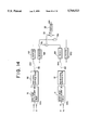
- FIG. 14 shows the embodiment 8 for measuring an electric energy of two elements such as a single-phase three-wire system or a three-phase three-wire system.
- FIG. 15 is a diagram explaining operation of the embodiment and
- FIG. 16 is a diagram explaining operation with an expanded time axis.
- first and second sigma-delta modulation circuits 10, 11 are the same as that shown in FIG. 2 or FIG. 3.
- a first digital low-pass filter 80 and a second digital low-pass filter 81 are the same as that shown in FIG. 5 and have n sets of delay means.
- Thinning-out means 181, 182 carry out a thinning-out operation at a ratio of 1/m. Note, m is a value equal to or larger than n.
- a switch SW5 fetches an input i 1 and at the time a switch SW6 fetches an input v 1 .
- a switch SW7 is connected to an i 1 register 191 and a switch SW8 is connected to a v 1 register 201.
- the first digital low-pass filter 80 outputs a train of sampled values of an AC current through the first sigma-delta modulation circuit 10.
- the thinning-out means 181 supplies a m-th train of sampled value to the i 1 register 191.
- the second digital low-pass filter 81 outputs a train of sampled values of an AC voltage through the second sigma-delta modulation circuit 11.
- the thinning-out means 182 supplies a m-th train of sampled value to the v 1 register 201.
- FIG. 15 shows the detail of the operation, wherein m is set to a value 8 and an eighth value i 17 of a train of sampled values i 10 -i.sub. ⁇ is thinned out with respect to the input i 1 and stored in the i 1 register 191 as i 1b and an eighth value v 17 of a train of sampled values v 10 -v 17 is thinned out with respect to the input v 1 and stored in the v 1 register 201 as v 1b .
- i 1a , i 1b , i 1c , . . . , v 1a , v 1b , v 1c , . . . are successively fetched.
- the embodiment 8 is advantageous in that when it is applied to multi-element inputs such as a single-phase three-wire system, three-phase three-wire system, three-phase four-wire system and the like which need a plurality of AC currents and AC voltages, the sigma-delta modulation circuit and the digital low-pass filter can be used together, so that the circuit scale can be reduced to realize a low cost arrangement.
- the embodiment 8 can be applied to a circuit which does not need changeover of a switch.
- the embodiment 9 provides an electronic watt-hour meter including offset adjustment means capable of adjusting an offset.
- FIGS. 17 and 18 show the embodiment 9.
- the embodiment 9 includes an i offset register 193, a v offset register 203, subtracters 21a, 21b, 21c, 21d in addition to first and second sigma-delta modulation circuits 10, 11, first and second digital low-pass filters 80, 81 and thinning-out means 181, 182 which are arranged in the same way as those of the embodiment 8.
- a GND signal as a reference potential is fetched by selecting input switches SW9 and SW10 and data is fetched to and stored in the i offset register 193 and the v offset register 203, respectively.
- currents i 1 and i 2 are alternately fetched on a current side and voltages v 1 and v 2 are alternately fetched on a voltage side as shown in a diagram of FIG. 18 explaining the operation of embodiment 9.
- data is fetched to an i 1 register 191, an i 2 register 192, a v 1 register 201, and a v 2 register 202 in the same way as the embodiment 8.
- the embodiment 9 is advantageous in that a DC offset which exists in an analog circuit and causes an error of a measured electric energy can be adjusted and a high-precision electronic watt-hour meter can be realized by a small circuit arrangement without increasing the number of sigma-delta modulation circuits and digital low-pass filters.
- the embodiment 10 shown in FIG. 19 is a modification of the embodiment 9.
- w (i 1 ⁇ v 1 )-(i offset ⁇ v offset)+(i 2 ⁇ v 2 )-(i offset ⁇ v offset) is calculated by a different calculation circuit and resulting values are cumulated by a counter 30 to obtain an electric energy.
- An obtained result is the same as that of the embodiment 9 and correction is carried out by subtracting an offset electric power from an electric power prior to an offset adjustment.
- the embodiment 11 is a modification of the embodiments 9 and 10.
- the switch SW9 successively and repeatedly fetches GND, i 1 , and i 2 and the switch SW10 successively and repeatedly fetches GND, v 1 , and v 2 .
- the switches SW11, SW12 are also successively changed over including the i offset register 193 and the v offset register 203.
- FIG. 20 is a diagram explaining operation of the embodiment, wherein offset current and offset voltages at respective times are successively measured and used for adjustment.
- This embodiment is advantageous in that since an i offset and a v offset are fetched at all times, the embodiment is difficult to be affected by the variation due to a temperature, aged deterioration and the like of a DC offset existing in an analog circuit, so that a high-precision electronic watt-hour meter can be realized.
- the embodiment 12 shown in a block diagram of FIG. 21 provides an electronic watt-hour meter having delay means capable of adjusting a voltage phase angle.
- the embodiment 12 is arranged such that a P-stage shift register 211 is disposed between the second sigma-delta modulation circuit 11 and the second digital low-pass filter 81 in the arrangement of the embodiment 8.
- a P1 register 212 and a P2 register 213 are provided to determine the number of shifts of the P-stage.
- the thinning-out means 181 and 182 carry out a thinning-out operation at a ratio of 1/(m+P). Note, m is a value equal to or larger than n (n: the number of stages the digital low-pass filter of FIG. 5).
- the P-stage shift register 211 When an AC voltage signal v 1 is fetched, the P-stage shift register 211 is connected to the second digital low-pass filter 81 in response to an output of the shift stage number according to a P1 value stored in the P1 register 212. Consequently, a phase of the AC voltage signal v 1 is delayed by a period of time corresponding to the number of stages of the P-stage shaft register 211 as compared with that of an AC current signal i 1 .
- the P-stage shift register 211 when an AC voltage signal v 2 is fetched, the P-stage shift register 211 is connected to the second digital low-pass filter 81 in response to an output of the shift stage number according to a P2 value stored in the P2 register 213. Consequently, a phase of the AC voltage signal v 2 is delayed by a period of time corresponding to the number of stages of the P-stage shaft register 211 as compared with that of an AC current signal i 2 .
- This embodiment has an advantage as described below.
- an AC current signal is detected by a CT and an AC voltage signal is detected by a VT and a phase angle error is caused between a primary side and a secondary side by the detecting elements of the CT and VT at the time.
- the phase angle error of the CT and VT can be removed by the P-stage shift register 211, the P1 register 212 and the P2 register 213, so that a high-precision electronic watt-hour meter with a small circuit scale can be provided.
- the embodiment 13 shown in a block diagram of FIG. 22 provides an electronic watt-hour meter having delay means capable of adjusting a current phase angle.
- This embodiment is arranged such that a P-stage shift register 214, a P1 register 215 and a P2 resister 216 are provided on a current side in the embodiment 8.
- phases of AC current signals i 1 and i 2 can be delayed by a period of time corresponding to the number of stages of the P-stage shift resister as compared with those of AC voltage signals v 1 and v 2 .
- phase angles of a voltage and a current can be optionally adjusted by combining the embodiment 13 with the embodiment 12.
- the embodiment 14 provides an electronic watt-hour meter including balance adjustment means capable of carrying out a balance adjustment for measuring multi-element inputs in such cases as a single-phase three-wire system, three-phase three-wire system, three-phase four-wire system and the like.
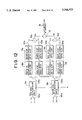
- FIG. 23 shows a block diagram of a 3-element watt-hour meter for measuring an electric energy of the three-phase four-wire system.
- the arrangement of the embodiment 14 up to an i 1 register 191, an i 2 register 192, an i 3 register 194, a v 1 register 201, a v 2 register 202, and a v 3 register 204 is the same as that of the embodiment 8 except that it is applied to the three-phase four-wire system.
- the embodiment 14 becomes a 2-element watt-hour meter because it is only necessary to check the balance of i 1 , i 3 , v 1 , v 3 and in this case the adjustment register 222 is removed.
- the embodiment 14 has the following advantage. When a measurement is made for multi-elements, each element has an error causing factor such as VT, CT and the like. Since the embodiment 14 has the balance adjustment registers 221 and 222 to match measuring precisions between respective elements, however, the embodiment can provide a high-precision watt-hour meter by adjusting values in the registers.
- the embodiment 15 shown in a block diagram of FIG. 24 provides an electronic watt-hour meter including balance adjustment means capable of carrying out a balance adjustment in the same way as the embodiment 14.
- the operation of the embodiment 15 is also the same as that of the embodiment 14.
- the embodiment 15 has the same advantage as that of the embodiment 14.
- the embodiment 16 provides an electronic watt-hour meter including potential operation preventing means for preventing the watt-hour meter from starting when no input is applied thereto.
- FIG. 25 is a block diagram showing a single-element watt-hour meter for measuring an electric energy of a single-phase two-wire system and
- FIG. 27a shows an operating waveform of the watt-hour meter.
- first and second sigma-delta modulation circuits 10, 11 are the same as those shown in FIG. 2 or FIG. 3 and first and second digital low-pass filters are the same as that shown in FIG. 5.
- An AC current signal i and an AC voltage signal v are subjected to A/D conversion by the sigma-delta modulation circuits 10, 11 and the first and second digital low-pass filters 80, 81.
- Current data and voltage data each subjected to the A/D conversion are multiplied by a multiplier 50 to calculate instantaneous electric power data.
- a one pulse is output from a magnitude comparator 233 (FIG. 27a (2)) to set (w n -rated reference value) to the register 232.
- a pulse output from the magnitude comparator 233 is compared with a start reference value (S) of a start reference value setting unit 236 by a pulse cycle detection circuit 235.
- the AND gate 237 when the pulse cycle is less than the start reference value, the AND gate 237 outputs pulses, whereas when the pulse cycle is equal or greater than the start reference value, the AND gate outputs no pulse (FIG. 27a (4)).
- a counter 30 cumulates the pulses to obtain an electric energy. More specifically, when the electric energy per unit time is small, the electric energy is not counted.
- the embodiment 16 is advantageous in that since a start current is detected in such a manner that a pulse is output by the accumulator 231, the register 232 and the magnitude comparator 233 and a cycle of the pulse is detected, there is provided a potential operation preventing function for preventing unnecessary measurement due to a DC component at an analog unit when no current flows.
- the embodiment 17 provides an electronic watt-hour meter including a potential operation preventing means for preventing the watt-hour meter from starting when no input is applied thereto in the same way as the embodiment 16.
- FIG. 26 is a block diagram showing a single-element watt-hour meter for measuring an electric energy of a single-phase two-wire system and
- FIG. 27b shows an operating waveform of the watt-hour meter.
- the embodiment 17 is arranged by adding a third digital low-pass filter 82 to the arrangement of the embodiment 16.
- the operation of the embodiment 17 thereafter is the same as that of the embodiment 16.
- an output from the register 232 is averaged as shown in FIG. 27b (1) and contributes to the improvement in the measuring precision.
- the embodiment 17 is advantageous in that it can detect a high-precision start current by the addition of the third digital low-pass filter 82.
- the embodiment 18 shown in a block diagram of FIG. 28 provides an electronic watt-hour meter including a light load adjusting means for carrying out adjustment when a light load is applied.
- the embodiment 18 is arranged by adding a light load adjustment setting unit (register) 241 and an adder 50 for adding a light load adjustment value to the arrangement of the embodiment 16 shown in FIG. 25.
- a light load adjustment is carried out by adding a light load adjustment value L in the light load adjustment setting unit 241 to a quantized electric power value which is an output from a multiplier 18j.
- the reason why the light load adjustment is carried out is that when a CT as an AC current detecting element is used, since a small current region has a tendency to have a minus error as shown in FIG. 29, a CT error is corrected by adding the certain value L by the light load adjustment register 241.
- w n (w 0 +L)+w n-1 (w n : an output value from a register 232 at a time t n , W n-1 : an output value from the register 232 at a time t n-1 ).
- the operation of the embodiment 18 after the addition of the light load adjustment value is the same as that of the embodiment 16.
- the light load adjustment value is also added in other regions as a certain value in addition to the region where the light load is applied. Since this value is relatively small, however, it can be ignored as a ratio of error in the other regions.
- the embodiment 18 is advantageous in that it can provide a high-precision watt-hour meter by correcting a CT error when a light load is applied.
- the embodiment 18 adds a light load adjustment value in regions other than the region in which a light load is applied
- the embodiment 19 adds the light load adjustment value only when a light load is applied.
- numeral 242 denotes a comparator
- numeral 243 denotes a reference current setting unit (register) for setting a reference current value
- numeral SW17 denotes a switch to be opened and closed by the comparator 242.
- a light load adjustment value L is added depending upon a current value from a first digital low-pass filter 80. More specifically, when the current value is a light load and equal to or less than a reference current value, the comparator 242 does not operate and the switch S17 is connected to the light load adjustment setting unit to add the light load adjustment value. When the current value is other than the light load and greater than the reference current value, the comparator 242 operates and the switch SW17 is not connected to the light load adjustment setting unit so that no light load setting value is added. After the addition of the light load adjustment value, the embodiment 19 operates in the same way as the embodiment 16.
- the embodiment 19 is as advantageous as the embodiment 18, since the light load adjustment value is added only when a light load is applied, the embodiment 19 can provide an electronic watt-hour meter of higher precision.
- the embodiment 20 shown in a block diagram of FIG. 31 provides an electronic watt-hour meter capable of measuring a measurement precision in a fine current region in a short time.
- the embodiment 20 is arranged such that, in the arrangement of the embodiment 18, a third digital low-pass filter 82 is interposed between the multiplier 18j and the adder 50, a first register 251 is interposed between the adder 50 and the accumulator 231 to store a value w 0 +L, and a second register 252 is connected to the output of the accumulator 231.
- a result of the addition of an output from the third digital low-pass filter 82 to a light load is stored in a first register 251 in synchronism with an operation clock (CLK) frequency f.
- the operation clock (CLK) frequency is executed in synchronism with a speed f ⁇ n. That is, the value (w 0 +L) stored in the first register 251 is cumulated n times and stored in the second register 252.
- a magnitude comparator 233 disposed behind the second register 252 operates in the same way as the embodiment 18 and pulses are cumulated by a counter 30 to obtain an electric energy.
- the embodiment 20 is advantageous in that pulse output intervals from the magnitude comparator are reduced and a measurement precision in a fine current region can be measured in a short time.
- the light load adjustment value is added in the embodiment 20, this embodiment is also applicable to the embodiments 16 and 17 in which a light load adjustment setting unit is omitted and a similar advantage can be obtained.
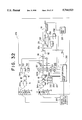
- the embodiment 21 is arranged as a typical electronic watt-hour meter for a three-phase four-wire system and includes adjustment means necessary to the measurement of an electric energy of the system so that a necessary adjustment can be carried out by the adjustment means.
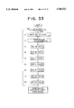
- FIG. 32 shows a block diagram of the embodiment 21 and
- FIG. 33 shows a flowchart of the adjustment.
- Numeral 261 denotes a display unit for displaying a cumulated electric energy
- numeral 260 denotes an calculating operation control circuit for controlling an entire calculating operation
- numeral 270 denotes the electronic watt-hour meter as a whole
- numeral 301 denotes an analog reference generator for inputting a reference input
- Numeral 241 denotes a light load adjustment value setting unit for setting a light load adjustment value L
- numeral 234 denotes a rated reference value setting unit for setting a rated reference value F.
- the arithmetic operation control circuit 260 has an adjustment mode and carries out the following operation.
- the reference electric power means a calculated value which is obtained by multiplying a voltage from the analog reference generator 301 by a current therefrom, and the rated reference value means a calculated value (constant) for determining the number of pulses per unit electric energy.
- F means a corrected rated reference value and is set as a new rated reference value. More specifically, an input electric energy (a value of the register 232) becomes an electric energy corrected based on F (an output from a magnitude comparator) and thus a precise electric energy (the value of a counter 30) is measured.
- the respective setting values are set in the sequence of (1)-(8) and thereafter an electric energy is measured based on the determined set values.
- FIG. 33 shows a flowchart of the adjustment operation, wherein items (1)-(8) in the figure correspond to the above adjustments effected in (1)-(8).
- An adjustment job can be automatically carried out according to the flowchart.
- the balance adjustment in (2) and (3) is not needed.
- the light load adjustment in (5) is not needed.
- the phase angle adjustment in (6), (7) and (8) is not needed.
- the constant K set in (6), (7), (8) is a constant determined by a sampling frequency f s and a commercially available frequency f 0 and expressed as follows on the premise that a phase angle error is 1 minute and an electric power error is about 0.05%.
- This embodiment is advantageous in that since the respective adjustment values are set and stored as digital values, an electronic watt-hour meter can be made in an automated line which does not need manpower and thus its cost can be reduced.
- the electronic watt-hour meter comprises first and second analog to digital conversion means for quantizing an AC current and an AC voltage, respectively, first and second moving average processing means for determining a moving average of each of the quantized AC current and the quantized AC voltage, first multiplication means for multiplying the AC current and the AC voltage each subjected to the moving average processing, and cumulation means for cumulating outputs from the multiplication means.
- the electronic watt-hour meter according to a second aspect of the invention is provided with thinning-out means for thinning out the quantized AC current and the quantized AC voltage each having been subjected to said moving average processing from the sampled value train thereof at a ratio of 1/n (n ⁇ 1).
- the electronic watt-hour meter is arranged such that the analog to digital conversion means of the invention a sigma-delta modulation circuit for integrating an analog input value by an integrator and outputting a digital value through a comparator as well as delaying and digital to analog converting the output so that the output is fed back to the input of the integrator and the electronic watt-hour meter comprises switching means for switching a plurality of inputs at a predetermined cycle and successively inputting the respective inputs to the sigma-delta modulation circuit and holding means for holding integrated values which are successively integrated by the integrator in synchronism with the switching cycle of the switching means in correspondence with the plurality of the respective inputs, respectively.
- the electronic watt-hour meter according to a fourth aspect of the invention is arranged such that the first and second moving average processing means has an output of 8 bits or less.
- the electronic watt-hour meter comprises first analog to digital conversion means for quantizing an AC current, second analog to digital conversion means for quantizing an AC voltage, first and second digital low-pass filters for causing the quantized AC current and AC voltage to pass through a low-pass region, respectively, thinning-out means for thinning out the quantized current and the quantized voltage each having been subjected to the low-pass filtration from the sampled value train thereof at a ratio of 1/m (m: a number larger than the number of delay means of the first and second digital low-pass filters), first multiplication means for multiplying an AC current and an AC voltage from the thinning-out means, and cumulation means for cumulating outputs from the multiplication means.
- the electronic watt-hour meter is provided with first and second integration means for integrating each one cycle of a quantized AC current and a quantized AC voltage, second multiplication means for multiplying outputs from the respective integration means, and subtracting means for subtracting an output from the second multiplication means from an output from the first multiplication means.
- the electronic watt-hour meter is provided with zero-cross detection means for detecting one cycle of a quantized AC current and a quantized AC voltage by a zero-cross point of the AC voltage, first and second integration means for integrating each one cycle of the quantized AC current and the quantized AC voltage based on an output from the zero-cross detection means, second multiplication means for multiplying outputs from the respective integration means, and subtracting means for subtracting an output from the second multiplication means from an output from the first multiplication means.
- the electronic watt-hour meter comprises switching means for successively fetching AC currents and AC voltages of respective elements having multiple inputs from input AC currents and AC voltages of the corresponding elements at a predetermined cycle, first analog to digital conversion means and second analog to digital conversion means for successively quantizing AC currents and AC voltages of the respective elements from the switching means, first and second digital low-pass filters for causing the quantized AC currents and AC voltages of the respective elements to successively pass through a low-pass region, thinning-out means for thinning out the quantized currents and the quantized voltages of the respective elements each having been subjected to the low-pass filtration from the sampled value train thereof at a ratio of 1/m (m: a number larger than the number of delay means of the first and second digital low-pass filters), calculation means for multiplying AC currents and AC voltages which correspond to the multiple inputs and are supplied from the thinning-out means and determining sums of the multiplication results, and cumulation means for cum
- the electronic watt-hour meter according to a ninth aspect of the invention is arranged such that the first and second low-pass filters are filters each having an output of 8 bits or less.
- the electronic watt-hour meter according to a tenth aspect of the invention is provided with an offset adjustment means for subtracting an offset electric power value from a quantized electric power value.
- the electronic watt-hour meter according to an eleventh aspect of the invention is provided with an offset adjustment means for subtracting an offset electric power value from a quantized electric power value.
- the electronic watt-hour meter according to a twelfth aspect of the invention is provided with delay means capable of obtaining a desired delay time interposed between the second analog to digital conversion means and the second digital low pass filter.
- the electronic watt-hour meter according to thirteenth aspect of the invention is provided with delay means capable of obtaining a desired delay time interposed between the first analog to digital conversion means and the first digital low pass filter.
- the electronic watt-hour meter according to a fourteenth aspect of the invention is arranged such that the delay means is a shift register capable of carrying out the desired number of shifts.
- the electronic watt-hour meter is provided with a balance adjustment means for multiplying quantized electric power values of respective 2, 3, . . . n elements by balance adjustment values B2, B3, . . . Bn in a case of multi-element inputs for inputting AC currents and AC voltages of n elements.
- the electronic watt-hour meter is provided with a potential operation preventing means for resetting a cumulated value of quantized electric power values each time the cumulated value exceeds a preset rated reference value to repeat cumulation as well as measuring a time until the cumulated value of the electric power values exceeds the rated reference value, and not measuring electric power values within the measuring time when the time exceeds a predetermined time.
- the electronic watt-hour meter according to a seventeenth aspect of the invention is provided with a third low-pass filter for causing a quantized electric power to pass through a low-pass region.
- the electronic watt-hour meter according to an eighteenth aspect of the invention is provided with a light load adjustment means for adding a predetermined light load adjustment value to a quantized electric power at least when a light load is applied.
- the electronic watt-hour meter is provided with a third digital low-pass filter operating at a predetermined clock cycle frequency f and causing a quantized electric power value to pass through a low-pass region, a first register for storing an output value having passed through the third digital low-pass filter, a second register for operating at an operating clock frequency f ⁇ n and adding a value of the first register n times and storing a resulting value, and comparison means for comparing a value output from the second register with a preset rated reference value at the operating clock cycle f ⁇ n and sending an output for calculating an electric energy each time a compared result exceeds the rated reference value.
- the electronic watt-hour meter according to a twentieth aspect of the invention is provided with rating adjustment means for outputting an inputted electric energy as an electric energy corrected based on a rated reference value.
- the electronic watt-hour meter comprises switching means for successively switching at a predetermined cycle and outputting respective currents and voltages entered from a first phase, a second phase and a third phase;
- first and second analog to digital conversion means for quantizing AC currents and AC voltages of the respective phases output from the switching means, respectively;
- first and second digital low-pass filters for causing the quantized AC currents and the quantized AC voltages of the respective phases to pass through a low-pass region, respectively;
- thinning-out means for thinning out the quantized AC currents and the quantized AC voltages of the respective phases each having been subjected to the low-pass filtration from the sampled value train thereof at a ratio of 1/m;
- calculation means for multiplying the AC currents of the respective phases from the thinning means by the AC voltages of the respective phases from the thinning means, respectively and determining sums of the multiplication results
- third low-pass filter for causing the outputs of the sums to pass through a low-pass region
- cumulating means for cumulating an output from the third digital low-pass filter; as well as
- a AC current and an AC voltage as analog values are quantized by the first and second analog to digital conversion means, the quantized signals are subjected to a moving average processing by the first and second moving average processing means, signals corresponding to the current and voltage, respectively are multiplied by the multiplier to obtain signals corresponding to electric powers and the signals are cumulated to obtain a high precision electric energy.
- a thinning-out operation is carried out by the 1/n thinning-out means (n ⁇ 1) to thin out the quantized AC current and the quantized AC voltage at a ratio of 1/n from the sampled value train thereof to reduce the number of calculation.
- a plurality of inputs are switched by the switching means at a predetermined cycle and successively entered to the sigma-delta modification circuit, the entered analog values are integrated by the integrator in the sigma-delta modification circuit and digital values are output through the comparator as well as fed back to the input of the integrator by being delayed and subjected to a D/A conversion.
- the first and second moving average processing means can measure an electric energy within a predetermined precision by an output of 8 bits or less.
- An AC current is digitized by the first analog to digital conversion means, an AC voltage is digitized by the second analog to digital conversion means, the digitized AC current and AC voltage are caused to pass through a low-pass region by the first and second low-pass filters, respectively, the AC current and AC voltage having been passed through the low-pass region are thinned out from the sampled value train thereof by the thinning-out means at a ratio of 1/m (m: a number larger than the number of delay means of the first and second digital low-pass filters), the AC current and AC voltage from the thinning-out means are multiplied by the first multiplication means, and outputs from the multiplication means are cumulated by the cumulation means to thereby obtain a high-precision electric energy.
- Each one cycle of an AC current and an AC voltage quantized by the first and second integration means is integrated by the first and second integration means, outputs therefrom are multiplied by the second multiplication means, and an output from the second multiplication means is subtracted from an output from the first multiplication means by the subtraction means to thereby reduce an electric power calculation error caused by the effect of a direct current component.
- a zero-cross point of an AC voltage is detected by the zero-cross detection means and each one cycle of a quantized AC current and AC voltage is detected based on the detection of the zero-cross point and an integrated value of each one cycle of the quantized AC current and an integrated value of each one cycle of the quantized AC voltage are output by the first and second integration means, even if a frequency varies, an effect of a direct current component of a current and a voltage can be removed.
- AC currents and AC voltages of respective multi-elements are successively fetched at a predetermined cycle from AC currents and AC voltages of the corresponding multi-elements entered by the switching means, the AC currents and AC voltages of the respective elements from the switching means are successively quantized by the first analog to digital conversion means and the second analog to digital conversion means, caused to successively pass through the low-pass region by the first and second digital low-pass filters, and thinned out by the thinning-out means at a ratio of 1/m (m: a number larger than the number of delay means of the first and second digital low-pass filters), AC currents and AC voltages from the thinning-out means which correspond to the multi-element inputs are multiplied, respectively, sums of the multiplied results are determined by the calculation means and outputs of the sums are cumulated by the cumulation means to obtain an electric energy.
- m a number larger than the number of delay means of the first and second digital low-pass filters
- the first and second digital low-pass filters measure an electric energy within a predetermined precision by an output of 8 bits or less.
- An offset electric power is calculated from a quantized offset current and a quantized offset voltage each determined by entering a reference current and a reference voltage and the result of calculation is set as the offset electric power value to the offset adjustment means and an offset adjustment is carried out by subtracting the offset electric power value from the quantized electric power value.
- An offset electric power is calculated from a quantized offset current and a quantized offset voltage determined by entering a reference current and a reference voltage at a predetermined cycle and the result of calculation is set as the offset electric power value to the offset adjustment means at each predetermined cycle and an offset adjustment is carried out by subtracting the offset electric power value from the quantized electric power value.
- a voltage phase angle is adjusted by the delay means to thereby correct a phase angle error.
- a a current phase angle is adjusted by the delay means to thereby correct a phase angle error.
- a phase angle is adjusted by the shift register capable of carrying out the desired number of shifts to thereby correct a phase angle error.
- a balance adjustment is carried out in such a manner that the respective balance adjustment values are multiplied through the multiplication means by the quantized electric power values of the respective second, third, . . . n-th elements determined from an AC current and an AC voltage of a usual object to be measured.
- the cumulated value is reset to repeat cumulation as well as a time until the cumulated value of the electric power values exceeds the rated reference value is measured, and when the time exceeds a predetermined time, electric power values within the measuring time are not measured for the prevention of a potential operation to thereby reduce a measuring error in the state of no entered electric energy.
- a potential operation of outputs having passed through the third digital low-pass filter is prevented to thereby reduce a measurement error in the state of no entered electric energy.
- a predetermined light load adjustment value is added to a quantized electric power value at least when a light load is applied to thereby reduce a measuring error in the light load.
- An electric power value quantized by the third digital low-pass filter operating at a predetermined operating clock frequency f is caused to pass through the low-pass region and stored in the first register.
- the value of the first register is added n times and a resulting value is stored in the second register operating at an operating clock frequency f ⁇ n.
- the value of the second register is compared with the preset rated reference value at an operating clock frequency of f ⁇ n and each time the value exceeds the rated reference value, an output for measuring an electric energy is sent by the comparison means to thereby measure a measuring precision in a short time.
- a previously set rated reference value is corrected in accordance with a ratio of a reference electric power value obtained in an actual measurement by inputting a reference current and a reference voltage to a reference electric power value calculated by multiplying the reference current by the reference voltage, the corrected rated reference value is set as the rated reference value of the rating adjustment means, and electric energies entered based on the rated reference value are output as corrected electric energies to thereby measure a precise electric energy by cumulating the outputs.
- Respective currents and voltages entered from a first phase, a second phase and a third phase are successively switched at a predetermined cycle and output by the switching means, and AC currents and AC voltages of the respective phases are quantized by the first and second analog to digital conversion means, respectively.
- the quantized AC currents and AC voltages are caused to pass through the low-pass region by the first and second digital low-pass filters, the quantized AC currents and the quantized AC voltages of the respective phases each having been subjected to the low-pass filtration are thinned out by the thinning-out means from the sampled value train thereof at a ratio of 1/m, the AC currents and the AC voltages of the respective phases from the thinning-out means are multiplied, respectively and the sums of the results of multiplication are determined by the calculation means, and outputs of the sums are caused to pass through the low-pass region by the third low-pass filter and cumulated by the cumulation means.
- the result of cumulation is adjusted by using at least one of the following adjustment means (1), (2), (3), (4).
- a high-precision electronic watt-hour meter by which a quantized noise in a low frequency region can be greatly reduced to thereby reduce an electric power error.
- the number of multiplications can be reduced, which is advantageous in that a power consumption of a circuit can be reduced.
- an advantage is obtained in that a plurality of inputs can be processed by a single sigma-delta modulation circuit and a circuit arrangement can be simplified by using time division.
- first and second moving average processing means can measure an electric energy within a predetermined precision range by an output of 8 bits or less.
- a high-precision electronic watt-hour meter by which a quantized noise in a low frequency region can be greatly reduced to thereby reduce an electric power error.
- the seventh aspect of the present invention since a zero-cross point of an AC voltage is detected by zero-cross detection means and each one cycle of a quantized AC current and an AC voltage is detected based thereon, there is an advantage that even if a frequency varies, an effect of a direct current component of a current and a voltage can be removed.
- an advantage is obtained in that a plurality of inputs can be processed by a single sigma-delta modulation circuit and a circuit arrangement can be simplified by using time division.
- first and second low-pass filters can measure an electric energy within a predetermined precision range by an output of 8 bits or less.
- a phase angle error is corrected by adjusting a phase angle by a shift register capable of carrying out the desired number of shifts, there is an advantage that a measuring precision can be improved.
- a measuring error can be reduced in the state that no electric energy is entered.
- the eighteenth aspect of the present invention since light load adjustment means is provided and a predetermined light load adjustment value is added at least when a light load is applied, there is an advantage that a measuring error can be reduced when the light load is applied.
- the nineteenth aspect of the present invention since an electric energy is measured at an operating clock frequency f ⁇ n, there is an advantage that a measuring precision can be measured in a short time and in particular a measuring precision in a fine current region can be measured in a short time.
- respective adjustment values are set and stored as digital values, they can be automatically set without the need of manpower, by which an advantage is obtained in that an electronic watt-hour meter can be made by an automated line and its cost can be reduced.
Landscapes
- Engineering & Computer Science (AREA)
- Physics & Mathematics (AREA)
- General Physics & Mathematics (AREA)
- Power Engineering (AREA)
- Radar, Positioning & Navigation (AREA)
- Remote Sensing (AREA)
- Measurement Of Current Or Voltage (AREA)
- Analogue/Digital Conversion (AREA)
Applications Claiming Priority (5)
| Application Number | Priority Date | Filing Date | Title |
|---|---|---|---|
| JP5-000472 | 1993-01-06 | ||
| JP47293 | 1993-01-06 | ||
| JP05314689A JP3080207B2 (ja) | 1993-01-06 | 1993-12-15 | 電子式電力量計 |
| JP5-314689 | 1993-12-15 | ||
| PCT/JP1994/000008 WO1994016334A1 (en) | 1993-01-06 | 1994-01-06 | Electronic watt-hour meter |
Publications (1)
| Publication Number | Publication Date |
|---|---|
| US5764523A true US5764523A (en) | 1998-06-09 |
Family
ID=26333468
Family Applications (1)
| Application Number | Title | Priority Date | Filing Date |
|---|---|---|---|
| US08/295,872 Expired - Lifetime US5764523A (en) | 1993-01-06 | 1994-01-06 | Electronic watt-hour meter |
Country Status (6)
Cited By (54)
| Publication number | Priority date | Publication date | Assignee | Title |
|---|---|---|---|---|
| US6058354A (en) * | 1997-08-25 | 2000-05-02 | Electrowatt Technology Innovation Ag | Electricity meter to measure electrical physical magnitudes which are parameters or functions of measured voltages and/or currents |
| US6112986A (en) * | 1997-12-08 | 2000-09-05 | Berger; Richard S. | Method and apparatus for accessing patient insurance information |
| US6304202B1 (en) * | 1999-09-24 | 2001-10-16 | Cirrus Logic, Inc. | Delay correction system and method for a voltage channel in a sampled data measurement system |
| US6377037B1 (en) * | 1996-08-01 | 2002-04-23 | Siemens Power Transmission And Distribution, Inc. | Watt-hour meter with digital per-phase power factor compensation |
| US6522982B1 (en) * | 1999-09-24 | 2003-02-18 | Cirrus Logic, Inc. | Energy-to-pulse converter systems, devices, and methods wherein the output frequency is greater than the calculation frequency and having output phasing |
| US6618684B1 (en) * | 2000-01-26 | 2003-09-09 | Elster Electricity, Llc | System and method for digitally compensating frequency and temperature induced errors in amplitude and phase shift in current sensing of electronic energy meters |
| US6653964B2 (en) * | 2001-07-31 | 2003-11-25 | Denso Corporation | Filtering method and A/D conversion apparatus having filtering function |
| US20040189499A1 (en) * | 2003-03-28 | 2004-09-30 | Ho-San Han | Sigma delta beamformer and method with reduced artifact |
| US20040232904A1 (en) * | 2001-08-28 | 2004-11-25 | Analog Devices, Inc. | Methods and apparatus for phase compensation in electronic energy meters |
| US20060028197A1 (en) * | 2004-08-05 | 2006-02-09 | Microchip Technology Incorporated | Direct current offset cancellation and phase equalization for power metering devices |
| US20060072271A1 (en) * | 2004-10-05 | 2006-04-06 | Ofi, Inc. | Electrical power distribution system |
| US20060108996A1 (en) * | 2004-11-08 | 2006-05-25 | Yi-Chou Huang | Digital power meter apparatus and method for the same |
| US20070083478A1 (en) * | 2003-10-27 | 2007-04-12 | Aisin Seiki Kabushiki Kaisha | Cogeneration implementation simulation method and system, and cogeneration device sail promotion method and system |
| US20080181338A1 (en) * | 2007-01-30 | 2008-07-31 | Ryuji Aono | Amplitude detection apparatus |
| US20080215264A1 (en) * | 2005-01-27 | 2008-09-04 | Electro Industries/Gauge Tech. | High speed digital transient waveform detection system and method for use in an intelligent device |
| US20080235355A1 (en) * | 2004-10-20 | 2008-09-25 | Electro Industries/Gauge Tech. | Intelligent Electronic Device for Receiving and Sending Data at High Speeds Over a Network |
| US7486782B1 (en) | 1997-09-17 | 2009-02-03 | Roos Charles E | Multifunction data port providing an interface between a digital network and electronics in residential or commercial structures |
| DE10239283B4 (de) * | 2001-08-27 | 2009-04-30 | Denso Corp., Kariya-shi | Synchrones Detektionsverfahren und Vorrichtung dafür, und Sensorsignaldetektor |
| US20090228224A1 (en) * | 2005-01-27 | 2009-09-10 | Electro Industries/Gauge Tech. | Intelligent electronic device with enhanced power quality monitoring and communications capabilities |
| EP2207042A1 (de) * | 2009-01-10 | 2010-07-14 | EMH Elektrizitätszähler GmbH & Co KG | Drehstromzähler |
| US20100324845A1 (en) * | 2005-01-27 | 2010-12-23 | Electro Industries/Gauge Tech. | Intelligent electronic device with enhanced power quality monitoring and communication capabilities |
| DE102010042946A1 (de) * | 2010-10-26 | 2012-04-26 | Lenze Se | Frequenzumrichter |
| US8218686B1 (en) * | 2008-04-18 | 2012-07-10 | Marvell International Ltd. | Circuit and method for DC offset compensation |
| US20120263262A1 (en) * | 2011-04-14 | 2012-10-18 | Broadcom Corporation | IQ Gain Imbalance Correction for Receivers Employing Sigma-Delta Analog to Digital Conversion |
| CN102934462A (zh) * | 2010-06-25 | 2013-02-13 | 恩莫杜斯有限公司 | 功率消耗的量化监测 |
| US20140167737A1 (en) * | 2012-12-18 | 2014-06-19 | Samsung Electro-Mechanics Co., Ltd. | Ac detection circuit and operating method thereof |
| US8797202B2 (en) | 2008-03-13 | 2014-08-05 | Electro Industries/Gauge Tech | Intelligent electronic device having circuitry for highly accurate voltage sensing |
| US8930153B2 (en) | 2005-01-27 | 2015-01-06 | Electro Industries/Gauge Tech | Metering device with control functionality and method thereof |
| US9316672B2 (en) | 2011-02-04 | 2016-04-19 | Fujitsu Limited | Power strip and power measurement method |
| US9482555B2 (en) | 2008-04-03 | 2016-11-01 | Electro Industries/Gauge Tech. | System and method for improved data transfer from an IED |
| US9891253B2 (en) | 2005-10-28 | 2018-02-13 | Electro Industries/Gauge Tech | Bluetooth-enabled intelligent electronic device |
| US9897461B2 (en) | 2015-02-27 | 2018-02-20 | Electro Industries/Gauge Tech | Intelligent electronic device with expandable functionality |
| US9903895B2 (en) | 2005-01-27 | 2018-02-27 | Electro Industries/Gauge Tech | Intelligent electronic device and method thereof |
| US9989618B2 (en) | 2007-04-03 | 2018-06-05 | Electro Industries/Gaugetech | Intelligent electronic device with constant calibration capabilities for high accuracy measurements |
| US10048088B2 (en) | 2015-02-27 | 2018-08-14 | Electro Industries/Gauge Tech | Wireless intelligent electronic device |
| US10275840B2 (en) | 2011-10-04 | 2019-04-30 | Electro Industries/Gauge Tech | Systems and methods for collecting, analyzing, billing, and reporting data from intelligent electronic devices |
| US10303860B2 (en) | 2011-10-04 | 2019-05-28 | Electro Industries/Gauge Tech | Security through layers in an intelligent electronic device |
| US10345416B2 (en) | 2007-03-27 | 2019-07-09 | Electro Industries/Gauge Tech | Intelligent electronic device with broad-range high accuracy |
| US10430263B2 (en) | 2016-02-01 | 2019-10-01 | Electro Industries/Gauge Tech | Devices, systems and methods for validating and upgrading firmware in intelligent electronic devices |
| US10641618B2 (en) | 2004-10-20 | 2020-05-05 | Electro Industries/Gauge Tech | On-line web accessed energy meter |
| US10771532B2 (en) | 2011-10-04 | 2020-09-08 | Electro Industries/Gauge Tech | Intelligent electronic devices, systems and methods for communicating messages over a network |
| US10845399B2 (en) | 2007-04-03 | 2020-11-24 | Electro Industries/Gaugetech | System and method for performing data transfers in an intelligent electronic device |
| US10862784B2 (en) | 2011-10-04 | 2020-12-08 | Electro Industries/Gauge Tech | Systems and methods for processing meter information in a network of intelligent electronic devices |
| US10958435B2 (en) | 2015-12-21 | 2021-03-23 | Electro Industries/ Gauge Tech | Providing security in an intelligent electronic device |
| US11009922B2 (en) | 2015-02-27 | 2021-05-18 | Electro Industries/Gaugetech | Wireless intelligent electronic device |
| US11307227B2 (en) | 2007-04-03 | 2022-04-19 | Electro Industries/Gauge Tech | High speed digital transient waveform detection system and method for use in an intelligent electronic device |
| US11644490B2 (en) | 2007-04-03 | 2023-05-09 | El Electronics Llc | Digital power metering system with serial peripheral interface (SPI) multimaster communications |
| US11686749B2 (en) | 2004-10-25 | 2023-06-27 | El Electronics Llc | Power meter having multiple ethernet ports |
| US11686594B2 (en) | 2018-02-17 | 2023-06-27 | Ei Electronics Llc | Devices, systems and methods for a cloud-based meter management system |
| US11734396B2 (en) | 2014-06-17 | 2023-08-22 | El Electronics Llc | Security through layers in an intelligent electronic device |
| US11734704B2 (en) | 2018-02-17 | 2023-08-22 | Ei Electronics Llc | Devices, systems and methods for the collection of meter data in a common, globally accessible, group of servers, to provide simpler configuration, collection, viewing, and analysis of the meter data |
| US11754997B2 (en) | 2018-02-17 | 2023-09-12 | Ei Electronics Llc | Devices, systems and methods for predicting future consumption values of load(s) in power distribution systems |
| US11816465B2 (en) | 2013-03-15 | 2023-11-14 | Ei Electronics Llc | Devices, systems and methods for tracking and upgrading firmware in intelligent electronic devices |
| US11863589B2 (en) | 2019-06-07 | 2024-01-02 | Ei Electronics Llc | Enterprise security in meters |
Families Citing this family (14)
| Publication number | Priority date | Publication date | Assignee | Title |
|---|---|---|---|---|
| DE19526723C1 (de) * | 1995-07-21 | 1997-02-13 | Siemens Ag | Elektrizitätszähler |
| DE19532588C1 (de) * | 1995-09-04 | 1997-03-06 | Siemens Ag | Elektrizitätszähler |
| TW396276B (en) * | 1996-03-01 | 2000-07-01 | Toshiba Corp | Arithmetic unit |
| DE19630605A1 (de) * | 1996-07-29 | 1998-02-05 | Tech Gmbh Antriebstechnik Und | Multiplikationsschaltung für Leistungs-Meßgerät |
| DE19639410A1 (de) * | 1996-09-25 | 1998-04-02 | Siemens Ag | Meßeinrichtung für elektrische Leistung |
| JP4127676B2 (ja) * | 2002-03-25 | 2008-07-30 | 三菱電機株式会社 | 電子式電力量計および電力関連量演算回路 |
| DE10311777B4 (de) * | 2003-03-18 | 2005-10-20 | Thomas Schoch | Verfahren, Messsystem und Vorrichtung zur elektrischen Leistungsmessung |
| DE10334517B4 (de) | 2003-07-29 | 2006-06-14 | Texas Instruments Deutschland Gmbh | Messgerät für elektrische Energie für ein Wechselstromnetz |
| DE10361664B4 (de) * | 2003-12-30 | 2009-08-13 | Austriamicrosystems Ag | Energiezähleranordnung |
| DE102004010707B4 (de) | 2004-03-04 | 2013-08-22 | Austriamicrosystems Ag | Energiezähleranordnung und Verfahren zum Kalibrieren |
| JP2010048635A (ja) * | 2008-08-21 | 2010-03-04 | Hitachi Ltd | レーダ装置 |
| KR101029016B1 (ko) * | 2009-04-27 | 2011-04-14 | 주식회사 유신 | 오차 보정 기능을 갖는 전력 계측기 및 위상 오차 보정 방법 |
| CN103091550B (zh) * | 2013-01-08 | 2015-02-11 | 北京优科利尔能源设备有限公司 | 一种宽电压与大电流同步隔离采样直流功率计 |
| CN108918929B (zh) * | 2018-09-11 | 2020-12-04 | 广东石油化工学院 | 一种负荷分解中功率信号自适应滤波方法 |
Citations (26)
| Publication number | Priority date | Publication date | Assignee | Title |
|---|---|---|---|---|
| US4459546A (en) * | 1980-11-03 | 1984-07-10 | Rockwell International Corporation | Electronic kilowatthour meter |
| US4564831A (en) * | 1982-07-02 | 1986-01-14 | Transamerica Delaval Inc. | Analog to digital converters for converting a plurality of different input signals |
| WO1986003302A1 (en) * | 1984-11-24 | 1986-06-05 | Crest Energy Scan Limited | A wattmeter circuit |
| US4672555A (en) * | 1984-10-18 | 1987-06-09 | Massachusetts Institute Of Technology | Digital ac monitor |
| JPS62185174A (ja) * | 1986-02-04 | 1987-08-13 | シ−メンス、アクチエンゲゼルシヤフト | 電子式電力量計 |
| EP0269827A1 (de) * | 1986-11-04 | 1988-06-08 | BBC Brown Boveri AG | Digitales Messgerät |
| US4752731A (en) * | 1985-06-14 | 1988-06-21 | Mitsubishi Denki Kabushiki Kaisha | Electronic type electric energy meter |
| US4907165A (en) * | 1985-06-19 | 1990-03-06 | Mitsubishi Denki Kabushiki Kaisha | Electric energy measuring method |
| US4992725A (en) * | 1988-12-26 | 1991-02-12 | Nec Corporation And The Tokyo Electric Power Company, Incorporated | Meter for accurately measuring integrated electric power |
| JPH03118483A (ja) * | 1989-08-15 | 1991-05-21 | Analog Devices Inc <Adi> | 電力測定装置 |
| US5068818A (en) * | 1989-06-06 | 1991-11-26 | Mitbushi Denki Kabushiki Kaisha | Hardware implemented moving average processor |
| EP0462045A1 (en) * | 1990-06-14 | 1991-12-18 | Transdata, Inc. | Digital power metering |
| US5081413A (en) * | 1989-02-23 | 1992-01-14 | Ohkura Electric Co., Ltd. | Method and apparatus for measuring AC power |
| US5099195A (en) * | 1989-12-18 | 1992-03-24 | The General Electric Company, P.L.C. | Electronic device for measuring electrical power supply to a load |
| US5134578A (en) * | 1991-02-11 | 1992-07-28 | General Electric Company | Digital signal processor for selectively performing cordic, division or square-rooting procedures |
| US5151866A (en) * | 1990-03-30 | 1992-09-29 | The Dow Chemical Company | High speed power analyzer |
| US5170115A (en) * | 1990-08-23 | 1992-12-08 | Yokogawa Electric Corporation | Sampling type measuring device |
| US5200750A (en) * | 1990-11-22 | 1993-04-06 | Yamaha Corporation | Digital-to-analog converter with noise-free sigma-delta modulation |
| JPH05333067A (ja) * | 1992-06-02 | 1993-12-17 | Mitsubishi Electric Corp | 電子式電力量計 |
| US5305004A (en) * | 1992-09-29 | 1994-04-19 | Texas Instruments Incorporated | Digital to analog converter for sigma delta modulator |
| US5329282A (en) * | 1992-03-02 | 1994-07-12 | Motorola, Inc. | Multi-bit sigma-delta analog-to-digital converter with reduced sensitivity to DAC nonlinearities |
| US5363101A (en) * | 1992-09-07 | 1994-11-08 | Sony Corporation | Analog to digital converter |
| US5396244A (en) * | 1992-11-09 | 1995-03-07 | U.S. Philips Corporation | Digital-to-analog converter |
| US5440503A (en) * | 1993-02-15 | 1995-08-08 | Nec Corporation | Digital filtering circuit operable as a three-stage moving average filter |
| US5461641A (en) * | 1992-07-10 | 1995-10-24 | International Business Machines Corporation | Decimation filter for a sigma-delta converter and A/D converter using the same |
| US5471209A (en) * | 1994-03-03 | 1995-11-28 | Echelon Corporation | Sigma-delta converter having a digital logic gate core |
Family Cites Families (1)
| Publication number | Priority date | Publication date | Assignee | Title |
|---|---|---|---|---|
| JPH02173576A (ja) * | 1988-12-27 | 1990-07-05 | Nec Corp | ディジタル電力量計 |
-
1993
- 1993-12-15 JP JP05314689A patent/JP3080207B2/ja not_active Expired - Fee Related
- 1993-12-24 TW TW082110957A patent/TW289088B/zh active
-
1994
- 1994-01-06 US US08/295,872 patent/US5764523A/en not_active Expired - Lifetime
- 1994-01-06 WO PCT/JP1994/000008 patent/WO1994016334A1/ja not_active Application Discontinuation
- 1994-01-06 EP EP94904001A patent/EP0634662A4/en not_active Withdrawn
- 1994-09-06 KR KR1019940703119A patent/KR950700548A/ko not_active Application Discontinuation
Patent Citations (28)
| Publication number | Priority date | Publication date | Assignee | Title |
|---|---|---|---|---|
| US4459546A (en) * | 1980-11-03 | 1984-07-10 | Rockwell International Corporation | Electronic kilowatthour meter |
| US4564831A (en) * | 1982-07-02 | 1986-01-14 | Transamerica Delaval Inc. | Analog to digital converters for converting a plurality of different input signals |
| US4672555A (en) * | 1984-10-18 | 1987-06-09 | Massachusetts Institute Of Technology | Digital ac monitor |
| WO1986003302A1 (en) * | 1984-11-24 | 1986-06-05 | Crest Energy Scan Limited | A wattmeter circuit |
| US4752731A (en) * | 1985-06-14 | 1988-06-21 | Mitsubishi Denki Kabushiki Kaisha | Electronic type electric energy meter |
| US4907165A (en) * | 1985-06-19 | 1990-03-06 | Mitsubishi Denki Kabushiki Kaisha | Electric energy measuring method |
| JPS62185174A (ja) * | 1986-02-04 | 1987-08-13 | シ−メンス、アクチエンゲゼルシヤフト | 電子式電力量計 |
| EP0269827A1 (de) * | 1986-11-04 | 1988-06-08 | BBC Brown Boveri AG | Digitales Messgerät |
| US4878185A (en) * | 1986-11-04 | 1989-10-31 | Bbc Brown Boveri Ag | Digital measuring instrument |
| US4992725A (en) * | 1988-12-26 | 1991-02-12 | Nec Corporation And The Tokyo Electric Power Company, Incorporated | Meter for accurately measuring integrated electric power |
| US5081413A (en) * | 1989-02-23 | 1992-01-14 | Ohkura Electric Co., Ltd. | Method and apparatus for measuring AC power |
| US5068818A (en) * | 1989-06-06 | 1991-11-26 | Mitbushi Denki Kabushiki Kaisha | Hardware implemented moving average processor |
| JPH03118483A (ja) * | 1989-08-15 | 1991-05-21 | Analog Devices Inc <Adi> | 電力測定装置 |
| US5099195A (en) * | 1989-12-18 | 1992-03-24 | The General Electric Company, P.L.C. | Electronic device for measuring electrical power supply to a load |
| US5151866A (en) * | 1990-03-30 | 1992-09-29 | The Dow Chemical Company | High speed power analyzer |
| EP0462045A1 (en) * | 1990-06-14 | 1991-12-18 | Transdata, Inc. | Digital power metering |
| US5170115A (en) * | 1990-08-23 | 1992-12-08 | Yokogawa Electric Corporation | Sampling type measuring device |
| US5200750A (en) * | 1990-11-22 | 1993-04-06 | Yamaha Corporation | Digital-to-analog converter with noise-free sigma-delta modulation |
| US5448747A (en) * | 1991-02-11 | 1995-09-05 | General Electric Company | Analog voltage metering system with programmable bit-serial digital signal processors |
| US5134578A (en) * | 1991-02-11 | 1992-07-28 | General Electric Company | Digital signal processor for selectively performing cordic, division or square-rooting procedures |
| US5329282A (en) * | 1992-03-02 | 1994-07-12 | Motorola, Inc. | Multi-bit sigma-delta analog-to-digital converter with reduced sensitivity to DAC nonlinearities |
| JPH05333067A (ja) * | 1992-06-02 | 1993-12-17 | Mitsubishi Electric Corp | 電子式電力量計 |
| US5461641A (en) * | 1992-07-10 | 1995-10-24 | International Business Machines Corporation | Decimation filter for a sigma-delta converter and A/D converter using the same |
| US5363101A (en) * | 1992-09-07 | 1994-11-08 | Sony Corporation | Analog to digital converter |
| US5305004A (en) * | 1992-09-29 | 1994-04-19 | Texas Instruments Incorporated | Digital to analog converter for sigma delta modulator |
| US5396244A (en) * | 1992-11-09 | 1995-03-07 | U.S. Philips Corporation | Digital-to-analog converter |
| US5440503A (en) * | 1993-02-15 | 1995-08-08 | Nec Corporation | Digital filtering circuit operable as a three-stage moving average filter |
| US5471209A (en) * | 1994-03-03 | 1995-11-28 | Echelon Corporation | Sigma-delta converter having a digital logic gate core |
Non-Patent Citations (2)
| Title |
|---|
| S. Mazor, "Approaching Filters Discretely", Computer Design, vol. 21, No. 4, Apr. 1982 Winchester, Mass. pp. 159-162. |
| S. Mazor, Approaching Filters Discretely , Computer Design, vol. 21, No. 4, Apr. 1982 Winchester, Mass. pp. 159 162. * |
Cited By (80)
| Publication number | Priority date | Publication date | Assignee | Title |
|---|---|---|---|---|
| US6377037B1 (en) * | 1996-08-01 | 2002-04-23 | Siemens Power Transmission And Distribution, Inc. | Watt-hour meter with digital per-phase power factor compensation |
| US6058354A (en) * | 1997-08-25 | 2000-05-02 | Electrowatt Technology Innovation Ag | Electricity meter to measure electrical physical magnitudes which are parameters or functions of measured voltages and/or currents |
| US7486782B1 (en) | 1997-09-17 | 2009-02-03 | Roos Charles E | Multifunction data port providing an interface between a digital network and electronics in residential or commercial structures |
| US6112986A (en) * | 1997-12-08 | 2000-09-05 | Berger; Richard S. | Method and apparatus for accessing patient insurance information |
| US6304202B1 (en) * | 1999-09-24 | 2001-10-16 | Cirrus Logic, Inc. | Delay correction system and method for a voltage channel in a sampled data measurement system |
| US6522982B1 (en) * | 1999-09-24 | 2003-02-18 | Cirrus Logic, Inc. | Energy-to-pulse converter systems, devices, and methods wherein the output frequency is greater than the calculation frequency and having output phasing |
| US6618684B1 (en) * | 2000-01-26 | 2003-09-09 | Elster Electricity, Llc | System and method for digitally compensating frequency and temperature induced errors in amplitude and phase shift in current sensing of electronic energy meters |
| US6653964B2 (en) * | 2001-07-31 | 2003-11-25 | Denso Corporation | Filtering method and A/D conversion apparatus having filtering function |
| DE10239283B4 (de) * | 2001-08-27 | 2009-04-30 | Denso Corp., Kariya-shi | Synchrones Detektionsverfahren und Vorrichtung dafür, und Sensorsignaldetektor |
| US20040232904A1 (en) * | 2001-08-28 | 2004-11-25 | Analog Devices, Inc. | Methods and apparatus for phase compensation in electronic energy meters |
| US6911813B2 (en) * | 2001-08-28 | 2005-06-28 | Analog Devices, Inc. | Methods and apparatus for phase compensation in electronic energy meters |
| US20040189499A1 (en) * | 2003-03-28 | 2004-09-30 | Ho-San Han | Sigma delta beamformer and method with reduced artifact |
| US7199738B2 (en) * | 2003-03-28 | 2007-04-03 | Siemens Medical Solutions Usa, Inc. | Sigma delta beamformer and method with reduced artifact |
| US20070083478A1 (en) * | 2003-10-27 | 2007-04-12 | Aisin Seiki Kabushiki Kaisha | Cogeneration implementation simulation method and system, and cogeneration device sail promotion method and system |
| US20060028197A1 (en) * | 2004-08-05 | 2006-02-09 | Microchip Technology Incorporated | Direct current offset cancellation and phase equalization for power metering devices |
| US20060072271A1 (en) * | 2004-10-05 | 2006-04-06 | Ofi, Inc. | Electrical power distribution system |
| US8000074B2 (en) * | 2004-10-05 | 2011-08-16 | 2D2C, Inc. | Electrical power distribution system |
| US11754418B2 (en) | 2004-10-20 | 2023-09-12 | Ei Electronics Llc | On-line web accessed energy meter |
| US20080235355A1 (en) * | 2004-10-20 | 2008-09-25 | Electro Industries/Gauge Tech. | Intelligent Electronic Device for Receiving and Sending Data at High Speeds Over a Network |
| US10641618B2 (en) | 2004-10-20 | 2020-05-05 | Electro Industries/Gauge Tech | On-line web accessed energy meter |
| US10628053B2 (en) | 2004-10-20 | 2020-04-21 | Electro Industries/Gauge Tech | Intelligent electronic device for receiving and sending data at high speeds over a network |
| US9080894B2 (en) | 2004-10-20 | 2015-07-14 | Electro Industries/Gauge Tech | Intelligent electronic device for receiving and sending data at high speeds over a network |
| US11686749B2 (en) | 2004-10-25 | 2023-06-27 | El Electronics Llc | Power meter having multiple ethernet ports |
| US7166995B2 (en) * | 2004-11-08 | 2007-01-23 | Fortune Semiconductor Corp. | Digital power meter apparatus and method for the same |
| US20060108996A1 (en) * | 2004-11-08 | 2006-05-25 | Yi-Chou Huang | Digital power meter apparatus and method for the same |
| US8930153B2 (en) | 2005-01-27 | 2015-01-06 | Electro Industries/Gauge Tech | Metering device with control functionality and method thereof |
| US11366143B2 (en) | 2005-01-27 | 2022-06-21 | Electro Industries/Gaugetech | Intelligent electronic device with enhanced power quality monitoring and communication capabilities |
| US8160824B2 (en) | 2005-01-27 | 2012-04-17 | Electro Industries/Gauge Tech | Intelligent electronic device with enhanced power quality monitoring and communication capabilities |
| US20080215264A1 (en) * | 2005-01-27 | 2008-09-04 | Electro Industries/Gauge Tech. | High speed digital transient waveform detection system and method for use in an intelligent device |
| US8190381B2 (en) * | 2005-01-27 | 2012-05-29 | Electro Industries/Gauge Tech | Intelligent electronic device with enhanced power quality monitoring and communications capabilities |
| US20090228224A1 (en) * | 2005-01-27 | 2009-09-10 | Electro Industries/Gauge Tech. | Intelligent electronic device with enhanced power quality monitoring and communications capabilities |
| US11366145B2 (en) | 2005-01-27 | 2022-06-21 | Electro Industries/Gauge Tech | Intelligent electronic device with enhanced power quality monitoring and communications capability |
| US8862435B2 (en) | 2005-01-27 | 2014-10-14 | Electric Industries/Gauge Tech | Intelligent electronic device with enhanced power quality monitoring and communication capabilities |
| US10823770B2 (en) | 2005-01-27 | 2020-11-03 | Electro Industries/Gaugetech | Intelligent electronic device and method thereof |
| US9903895B2 (en) | 2005-01-27 | 2018-02-27 | Electro Industries/Gauge Tech | Intelligent electronic device and method thereof |
| US8666688B2 (en) | 2005-01-27 | 2014-03-04 | Electro Industries/Gauge Tech | High speed digital transient waveform detection system and method for use in an intelligent electronic device |
| US8700347B2 (en) | 2005-01-27 | 2014-04-15 | Electro Industries/Gauge Tech | Intelligent electronic device with enhanced power quality monitoring and communications capability |
| US20100324845A1 (en) * | 2005-01-27 | 2010-12-23 | Electro Industries/Gauge Tech. | Intelligent electronic device with enhanced power quality monitoring and communication capabilities |
| US9891253B2 (en) | 2005-10-28 | 2018-02-13 | Electro Industries/Gauge Tech | Bluetooth-enabled intelligent electronic device |
| KR101009840B1 (ko) | 2007-01-30 | 2011-01-19 | 도시바 기카이 가부시키가이샤 | 진폭 검출 장치 |
| US8000414B2 (en) * | 2007-01-30 | 2011-08-16 | Toshiba Kikai Kabushiki Kaisha | Amplitude detection apparatus |
| US20080181338A1 (en) * | 2007-01-30 | 2008-07-31 | Ryuji Aono | Amplitude detection apparatus |
| US10345416B2 (en) | 2007-03-27 | 2019-07-09 | Electro Industries/Gauge Tech | Intelligent electronic device with broad-range high accuracy |
| US11644490B2 (en) | 2007-04-03 | 2023-05-09 | El Electronics Llc | Digital power metering system with serial peripheral interface (SPI) multimaster communications |
| US11635455B2 (en) | 2007-04-03 | 2023-04-25 | El Electronics Llc | System and method for performing data transfers in an intelligent electronic device |
| US10845399B2 (en) | 2007-04-03 | 2020-11-24 | Electro Industries/Gaugetech | System and method for performing data transfers in an intelligent electronic device |
| US11307227B2 (en) | 2007-04-03 | 2022-04-19 | Electro Industries/Gauge Tech | High speed digital transient waveform detection system and method for use in an intelligent electronic device |
| US9989618B2 (en) | 2007-04-03 | 2018-06-05 | Electro Industries/Gaugetech | Intelligent electronic device with constant calibration capabilities for high accuracy measurements |
| US8797202B2 (en) | 2008-03-13 | 2014-08-05 | Electro Industries/Gauge Tech | Intelligent electronic device having circuitry for highly accurate voltage sensing |
| US9482555B2 (en) | 2008-04-03 | 2016-11-01 | Electro Industries/Gauge Tech. | System and method for improved data transfer from an IED |
| US8526541B1 (en) * | 2008-04-18 | 2013-09-03 | Marvell International Ltd. | Method and apparatus for compensating for DC offset in a communication system |
| US8218686B1 (en) * | 2008-04-18 | 2012-07-10 | Marvell International Ltd. | Circuit and method for DC offset compensation |
| EP2207042A1 (de) * | 2009-01-10 | 2010-07-14 | EMH Elektrizitätszähler GmbH & Co KG | Drehstromzähler |
| US20130158911A1 (en) * | 2010-06-25 | 2013-06-20 | Enmodus Limited | Quantised monitoring of power-consumption |
| CN102934462A (zh) * | 2010-06-25 | 2013-02-13 | 恩莫杜斯有限公司 | 功率消耗的量化监测 |
| DE102010042946A1 (de) * | 2010-10-26 | 2012-04-26 | Lenze Se | Frequenzumrichter |
| US9316672B2 (en) | 2011-02-04 | 2016-04-19 | Fujitsu Limited | Power strip and power measurement method |
| US9014306B2 (en) * | 2011-04-14 | 2015-04-21 | Broadcom Corporation | IQ gain imbalance correction for receivers employing sigma-delta analog to digital conversion |
| US20120263262A1 (en) * | 2011-04-14 | 2012-10-18 | Broadcom Corporation | IQ Gain Imbalance Correction for Receivers Employing Sigma-Delta Analog to Digital Conversion |
| US10771532B2 (en) | 2011-10-04 | 2020-09-08 | Electro Industries/Gauge Tech | Intelligent electronic devices, systems and methods for communicating messages over a network |
| US10862784B2 (en) | 2011-10-04 | 2020-12-08 | Electro Industries/Gauge Tech | Systems and methods for processing meter information in a network of intelligent electronic devices |
| US10303860B2 (en) | 2011-10-04 | 2019-05-28 | Electro Industries/Gauge Tech | Security through layers in an intelligent electronic device |
| US10275840B2 (en) | 2011-10-04 | 2019-04-30 | Electro Industries/Gauge Tech | Systems and methods for collecting, analyzing, billing, and reporting data from intelligent electronic devices |
| US20140167737A1 (en) * | 2012-12-18 | 2014-06-19 | Samsung Electro-Mechanics Co., Ltd. | Ac detection circuit and operating method thereof |
| US11816465B2 (en) | 2013-03-15 | 2023-11-14 | Ei Electronics Llc | Devices, systems and methods for tracking and upgrading firmware in intelligent electronic devices |
| US11734396B2 (en) | 2014-06-17 | 2023-08-22 | El Electronics Llc | Security through layers in an intelligent electronic device |
| US10274340B2 (en) | 2015-02-27 | 2019-04-30 | Electro Industries/Gauge Tech | Intelligent electronic device with expandable functionality |
| US10048088B2 (en) | 2015-02-27 | 2018-08-14 | Electro Industries/Gauge Tech | Wireless intelligent electronic device |
| US11641052B2 (en) | 2015-02-27 | 2023-05-02 | El Electronics Llc | Wireless intelligent electronic device |
| US11644341B2 (en) | 2015-02-27 | 2023-05-09 | El Electronics Llc | Intelligent electronic device with hot swappable battery |
| US10739162B2 (en) | 2015-02-27 | 2020-08-11 | Electro Industries/Gauge Tech | Intelligent electronic device with surge supression |
| US11009922B2 (en) | 2015-02-27 | 2021-05-18 | Electro Industries/Gaugetech | Wireless intelligent electronic device |
| US9897461B2 (en) | 2015-02-27 | 2018-02-20 | Electro Industries/Gauge Tech | Intelligent electronic device with expandable functionality |
| US10958435B2 (en) | 2015-12-21 | 2021-03-23 | Electro Industries/ Gauge Tech | Providing security in an intelligent electronic device |
| US11870910B2 (en) | 2015-12-21 | 2024-01-09 | Ei Electronics Llc | Providing security in an intelligent electronic device |
| US10430263B2 (en) | 2016-02-01 | 2019-10-01 | Electro Industries/Gauge Tech | Devices, systems and methods for validating and upgrading firmware in intelligent electronic devices |
| US11754997B2 (en) | 2018-02-17 | 2023-09-12 | Ei Electronics Llc | Devices, systems and methods for predicting future consumption values of load(s) in power distribution systems |
| US11734704B2 (en) | 2018-02-17 | 2023-08-22 | Ei Electronics Llc | Devices, systems and methods for the collection of meter data in a common, globally accessible, group of servers, to provide simpler configuration, collection, viewing, and analysis of the meter data |
| US11686594B2 (en) | 2018-02-17 | 2023-06-27 | Ei Electronics Llc | Devices, systems and methods for a cloud-based meter management system |
| US11863589B2 (en) | 2019-06-07 | 2024-01-02 | Ei Electronics Llc | Enterprise security in meters |
Also Published As
| Publication number | Publication date |
|---|---|
| JP3080207B2 (ja) | 2000-08-21 |
| WO1994016334A1 (en) | 1994-07-21 |
| EP0634662A1 (en) | 1995-01-18 |
| JPH06258362A (ja) | 1994-09-16 |
| TW289088B (US07655688-20100202-C00086.png) | 1996-10-21 |
| KR950700548A (ko) | 1995-01-16 |
| EP0634662A4 (en) | 1995-08-16 |
Similar Documents
| Publication | Publication Date | Title |
|---|---|---|
| US5764523A (en) | Electronic watt-hour meter | |
| US5485393A (en) | Method and apparatus for measuring electrical parameters using a differentiating current sensor and a digital integrator | |
| US4943807A (en) | Digitally calibrated delta-sigma analog-to-digital converter | |
| US6058354A (en) | Electricity meter to measure electrical physical magnitudes which are parameters or functions of measured voltages and/or currents | |
| US5079510A (en) | Meter for accurately measuring integrated electric power | |
| US4282576A (en) | Indicator diagram based AC electric energy meter | |
| US6239589B1 (en) | Method and device for compensating for angle errors when measuring electrical power | |
| US5311117A (en) | Meter for accurately measuring integrated electric power | |
| CA2010100C (en) | Method and apparatus for measuring ac power | |
| WO2006083325A1 (en) | Direct current offset cancellation and phase equalization for power metering devices | |
| EP0321963B1 (en) | Impedance measuring apparatus | |
| US6509852B1 (en) | Apparatus and method for gain calibration technique for analog-to-digital converter | |
| JP2000338148A (ja) | 電子式電力量計 | |
| US6433723B1 (en) | Analog-to-digital conversion with reduced error | |
| US6373415B1 (en) | Digital phase compensation methods and systems for a dual-channel analog-to-digital converter | |
| JP2968607B2 (ja) | 無効電力量計 | |
| JPH05218876A (ja) | ディジタル信号処理方法及び装置 | |
| US5742156A (en) | Digital process for obtaining a measured parameter from an electric signal | |
| US6304202B1 (en) | Delay correction system and method for a voltage channel in a sampled data measurement system | |
| GB2152220A (en) | Compensating an electrical signal varying non-linearly with time | |
| JP2569248B2 (ja) | 電子式電力量計 | |
| KR100232764B1 (ko) | 디지털 거리 계전기의 임피던스 측정 장치 및 방법 | |
| JP4245791B2 (ja) | 電気保護装置 | |
| EP0554321B1 (en) | Method and apparatus for clamping the black level of a digital video signal | |
| JP3085496B2 (ja) | サンプリング式測定装置 |
Legal Events
| Date | Code | Title | Description |
|---|---|---|---|
| AS | Assignment |
Owner name: MITSUBISHI DENKI KABUSHIKI KAISHA, JAPAN Free format text: ASSIGNMENT OF ASSIGNORS INTEREST;ASSIGNORS:YOSHINAGA, TOORU;TAKAHASHI, KATUHIKO;TAMAI, SHINZOU;REEL/FRAME:007318/0970;SIGNING DATES FROM 19940830 TO 19940907 |
|
| FEPP | Fee payment procedure |
Free format text: PAYOR NUMBER ASSIGNED (ORIGINAL EVENT CODE: ASPN); ENTITY STATUS OF PATENT OWNER: LARGE ENTITY |
|
| STCF | Information on status: patent grant |
Free format text: PATENTED CASE |
|
| FPAY | Fee payment |
Year of fee payment: 4 |
|
| FPAY | Fee payment |
Year of fee payment: 8 |
|
| FPAY | Fee payment |
Year of fee payment: 12 |