US5697237A - Electric motor driven operating device - Google Patents
Electric motor driven operating device Download PDFInfo
- Publication number
- US5697237A US5697237A US08/599,818 US59981896A US5697237A US 5697237 A US5697237 A US 5697237A US 59981896 A US59981896 A US 59981896A US 5697237 A US5697237 A US 5697237A
- Authority
- US
- United States
- Prior art keywords
- turning
- driver
- electric motor
- lever
- rotary
- Prior art date
- Legal status (The legal status is an assumption and is not a legal conclusion. Google has not performed a legal analysis and makes no representation as to the accuracy of the status listed.)
- Expired - Fee Related
Links
Images

Classifications
-
- E—FIXED CONSTRUCTIONS
- E05—LOCKS; KEYS; WINDOW OR DOOR FITTINGS; SAFES
- E05B—LOCKS; ACCESSORIES THEREFOR; HANDCUFFS
- E05B81/00—Power-actuated vehicle locks
- E05B81/24—Power-actuated vehicle locks characterised by constructional features of the actuator or the power transmission
- E05B81/25—Actuators mounted separately from the lock and controlling the lock functions through mechanical connections
-
- E—FIXED CONSTRUCTIONS
- E05—LOCKS; KEYS; WINDOW OR DOOR FITTINGS; SAFES
- E05B—LOCKS; ACCESSORIES THEREFOR; HANDCUFFS
- E05B49/00—Electric permutation locks; Circuits therefor ; Mechanical aspects of electronic locks; Mechanical keys therefor
-
- Y—GENERAL TAGGING OF NEW TECHNOLOGICAL DEVELOPMENTS; GENERAL TAGGING OF CROSS-SECTIONAL TECHNOLOGIES SPANNING OVER SEVERAL SECTIONS OF THE IPC; TECHNICAL SUBJECTS COVERED BY FORMER USPC CROSS-REFERENCE ART COLLECTIONS [XRACs] AND DIGESTS
- Y10—TECHNICAL SUBJECTS COVERED BY FORMER USPC
- Y10T—TECHNICAL SUBJECTS COVERED BY FORMER US CLASSIFICATION
- Y10T292/00—Closure fasteners
- Y10T292/08—Bolts
- Y10T292/1043—Swinging
- Y10T292/1075—Operating means
- Y10T292/1082—Motor
-
- Y—GENERAL TAGGING OF NEW TECHNOLOGICAL DEVELOPMENTS; GENERAL TAGGING OF CROSS-SECTIONAL TECHNOLOGIES SPANNING OVER SEVERAL SECTIONS OF THE IPC; TECHNICAL SUBJECTS COVERED BY FORMER USPC CROSS-REFERENCE ART COLLECTIONS [XRACs] AND DIGESTS
- Y10—TECHNICAL SUBJECTS COVERED BY FORMER USPC
- Y10T—TECHNICAL SUBJECTS COVERED BY FORMER US CLASSIFICATION
- Y10T292/00—Closure fasteners
- Y10T292/57—Operators with knobs or handles
-
- Y—GENERAL TAGGING OF NEW TECHNOLOGICAL DEVELOPMENTS; GENERAL TAGGING OF CROSS-SECTIONAL TECHNOLOGIES SPANNING OVER SEVERAL SECTIONS OF THE IPC; TECHNICAL SUBJECTS COVERED BY FORMER USPC CROSS-REFERENCE ART COLLECTIONS [XRACs] AND DIGESTS
- Y10—TECHNICAL SUBJECTS COVERED BY FORMER USPC
- Y10T—TECHNICAL SUBJECTS COVERED BY FORMER US CLASSIFICATION
- Y10T70/00—Locks
- Y10T70/60—Systems
- Y10T70/625—Operation and control
- Y10T70/65—Central control
-
- Y—GENERAL TAGGING OF NEW TECHNOLOGICAL DEVELOPMENTS; GENERAL TAGGING OF CROSS-SECTIONAL TECHNOLOGIES SPANNING OVER SEVERAL SECTIONS OF THE IPC; TECHNICAL SUBJECTS COVERED BY FORMER USPC CROSS-REFERENCE ART COLLECTIONS [XRACs] AND DIGESTS
- Y10—TECHNICAL SUBJECTS COVERED BY FORMER USPC
- Y10T—TECHNICAL SUBJECTS COVERED BY FORMER US CLASSIFICATION
- Y10T70/00—Locks
- Y10T70/70—Operating mechanism
- Y10T70/7051—Using a powered device [e.g., motor]
- Y10T70/7062—Electrical type [e.g., solenoid]
- Y10T70/7107—And alternately mechanically actuated by a key, dial, etc.
-
- Y—GENERAL TAGGING OF NEW TECHNOLOGICAL DEVELOPMENTS; GENERAL TAGGING OF CROSS-SECTIONAL TECHNOLOGIES SPANNING OVER SEVERAL SECTIONS OF THE IPC; TECHNICAL SUBJECTS COVERED BY FORMER USPC CROSS-REFERENCE ART COLLECTIONS [XRACs] AND DIGESTS
- Y10—TECHNICAL SUBJECTS COVERED BY FORMER USPC
- Y10T—TECHNICAL SUBJECTS COVERED BY FORMER US CLASSIFICATION
- Y10T74/00—Machine element or mechanism
- Y10T74/18—Mechanical movements
- Y10T74/18056—Rotary to or from reciprocating or oscillating
- Y10T74/18288—Cam and lever
-
- Y—GENERAL TAGGING OF NEW TECHNOLOGICAL DEVELOPMENTS; GENERAL TAGGING OF CROSS-SECTIONAL TECHNOLOGIES SPANNING OVER SEVERAL SECTIONS OF THE IPC; TECHNICAL SUBJECTS COVERED BY FORMER USPC CROSS-REFERENCE ART COLLECTIONS [XRACs] AND DIGESTS
- Y10—TECHNICAL SUBJECTS COVERED BY FORMER USPC
- Y10T—TECHNICAL SUBJECTS COVERED BY FORMER US CLASSIFICATION
- Y10T74/00—Machine element or mechanism
- Y10T74/18—Mechanical movements
- Y10T74/18568—Reciprocating or oscillating to or from alternating rotary
- Y10T74/18792—Reciprocating or oscillating to or from alternating rotary including worm
Definitions
- the present invention relates to an electric motor driven operating device for blocking button of a door lock for central locking and unlocking of the doors of a motor vehicle.
- a central locking for the door lock of motor vehicle doors with an electrical position control is disclosed for example in the German patent document DE 40 15 522 A1 or DE 42 22 868 A1.
- the locking and unlocking buttons operate for manually locking individual door locks from opening, so that the doors can be opened only after the preceding unlocking of the locking or unlocking button.
- the unlocking is performed manually both by direct gripping of the blocking button and also by a door key through a linkage which is operated by the key and engages with the blocking button.
- each door lock is associated with an electric motor operated actuating device for additionally actuating the locking and unlocking button by an electric motor.
- This provides for the possibility of a simple central locking by electric control of the actuating devices by a single door lock, and thereby all electric motors of the actuating devices are started.
- Each electric motor transfers, through the transmission, the associated blocking button in its blocking or locking position in which it blocks the door lock or in its unlocking position in which it releases the door lock.
- the blocking or locking button which can be actuated manually is transferred by hand in its another position, the transmission together with the driven shaft and the rotor of the electric motor is moved. Thereby the force application during the handling of the blocking button is substantially increased, and therefore at least for the vehicles of the luxury class a reduced comfort must be taken into consideration.
- an electric motor driven actuating device for a blocking button of a door lock in which the transmission has a turning member which is turnable about a turning axis of a turning lever and is connected for joint rotation with the turning lever and also has a driver which is driven by the electric motor and is rotatable about a rotary axis extending parallel to the turning axis with a driver cam arranged at a radial distance from the rotary axis and rotates during rotation of the driver in a coulisse in the turning member, an end switch is provided which turns off the electric motor when after rotation of the driver by approximately 180° the driver cam assumes one of two end rotary positions located on a straight line intersecting the rotary axis of the driver and the turning axis of the turning member and the turning lever, and the coulisse is formed so that the turning member in each end rotary position of the driver cam is turnable by manual actuation of
- the connection of the turning member and the turning lever for joint rotation is performed by an overloading coupling which releases the rotary-fixed connection when a torque applied to the turning lever exceeds a predetermined value.
- an overloading coupling an emergency actuation of the blocking or locking button is ensured in the case of the current failure or a blocking of the turning member by the driver cam.
- the overload coupling can be released by increased force application and with the stationary turning member the turning lever is turned relative to it so that the blocking button can be transferred to its blocking or unblocking position.
- the blocking button can be actuated by the door key with increased force application for releasing the overloading coupling.
- such an overloading coupling is preferably formed so that arresting elements and arresting recesses are arranged in the facing end surfaces of the turning lever and the turning member.
- the arresting elements engage in the arresting recesses under the spring force of arresting springs.
- Arresting recesses are formed so that the arresting elements can move out of the arresting recesses when the overload torque is applied to the turning lever, and thereby interrupt the connection between the turning lever and the turning member.
- the end switch for switching the electric motor is needed for the positioning of the driver disc in its proper position in which the driver cam after rotation by 180° assumes one of its both end rotary positions.
- the end switch can be formed by contact springs which are held on the driver disc and electrically connected with one another and also contact paths which are arranged stationarily relative to the driver disc and are electrically isolated from one another. The contact springs displace on the contact paths.
- the end switch has three concentrically arranged contact paths and a slider with three contact springs each contacting a respective one of the contact paths.
- One of the contact paths extends over a peripheral angle of 360° while both other contact paths extend over substantially 180° each and are arranged opposite to one another.
- a corresponding contact spring runs over the associated semi-circular contact path while the other contact spring runs over its associated semi-circular contact path.
- the electric motor which is formed as a direct current motor is connected with a full circle contact path and two direct voltage potentials, for example the minus potential.
- the both semi-circular contact paths can be connected by the door key selectively to the other direct voltage potential, for example the plus potential.
- a control electronic device and a sensor which senses the end turning positions of the turning member and supplies a check-back signal of the axial position of the turning member to the control electronic device are provided so that, after the manual actuation of the blocking button, its motor actuation is performed reliably to the other position.
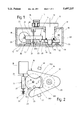
- FIG. 1 is a view showing a longitudinal section of an electric motor operated actuating device for a blocking button of a door lock
- FIG. 2 is a view from below of the transmission of the actuating device of FIG. 1;
- FIG. 3 is a principle electrical switching diagram of the actuating device of FIG. 1;
- FIGS. 4 and 5 each show a plan view of the construction of an end and position switch of FIG. 3 in two different switching positions
- FIG. 6 is a view showing a section VI in FIG. 1 on an enlarged scale.
- FIG. 1 An electric motor operated actuating device for a blocking button of a door lock in accordance with the present invention is shown in a longitudinal section in FIG. 1 and has a housing 10.
- a turning lever 11 with a bearing pin 12 is turnably supported in the housing 10.
- the turning axis of the turning lever 11 is identified with reference numeral 13.
- An actuating member 14 for a connecting rod 15 to a not shown locking or blocking button of a door lock is turnably supported on the turning lever 11 at a radial distance from the turning axis 13.
- the blocking button is transferred through the connecting rod 15 to its two end positions, in which it locks in a known manner the associated door lock from opening or releases the same for opening. This both end positions of the blocking button are identified hereinbelow as blocking and unblocking positions.
- the transmission 16 For motor turning of the turning lever 11, it is connected through a transmission 16 with a driven shaft 17 of an electric motor 18.
- the electric motor 18 is formed as a direct current motor and rotates only in one direction.
- the transmission 16 is formed so that the rotation of the driven shaft 17 is converted into a turning movement of the turning lever 11 in one or another turning direction.
- the transmission 16 has a driver fork 19 arranged on the axis 13 of the turning lever 11 and connected with the turning lever 11 through an overloading coupling 20 for joint rotation therewith. It also has a driver disc 21 which is rotatable about a rotary axis 22 extending parallel to the turning axis 13 and carries a driver pin 23 arranged at a radial distance from its rotary axis 22.
- the driver disc 21 is driven by the electric motor 18 in the rotary direction identified with the arrow 39 and is formed for this purpose as a worm wheel 24 which engages with a worm 25 arranged on the driven shaft 17 of the electric motor 18.
- the driver fork 19 has a fork opening 26 and is turnable between two abutments 27 and 28 in opposite turning directions.
- the abutment lever 19 as shown in FIG. 2, abuts against the lower end abutment 27 in FIG. 2, the turning lever 11 which is fixedly connected with the driver fork 19 is turned so fast that the blocking button is transferred to its end unblocking position.
- the driver lever 19 abuts against the upper end abutment 28, the turning lever 11 assumes such a turning position that the blocking button is located in its blocking position.
- the driver lever 19 is arranged freely rotatably on an end portion 29 of the bearing pin 12 of a reduced diameter for a turning movement. It is pressed by a spring disc 30 against the end surface 121 of the bearing pin 12.
- An overloading coupling 20 located between the driver fork 19 and the bearing pin 12 of the turning lever 11 has a plurality of arresting openings 31 arranged in the driver fork 19 and the same number of arresting elements 32 arranged in the end surface 121 of the bearing pin 12.
- the arresting elements 32 engage in the arresting openings 31 under the force of an arresting spring 33.
- the arresting opening 31 and the arresting element 32 are located concentrically to the turning axis 13 in opposite surfaces of the bearing pin 12 and the driver fork 19.
- a fragment of the overloading coupling 20 is shown in FIG.
- the arresting openings 31 are formed as semi-spherical depressions in the driver fork 19, while the arresting elements 32 are formed as spheres which are guided and held in axial openings 34 in the bearing pin 12 and pressed into the arresting openings 31 by the arresting springs 33 which are formed as pressure springs.
- the flanks of the semi-spherical depressions which serve as the arresting openings 31 are formed so that when the driver fork 19 is blocked and stationary and a torque is applied to the turning lever 11, and exceeds a predetermined value, the spherical arresting elements 32 laterally move out of the arresting openings 31 and therefore interrupt the connection between the driver fork 19 and the turning lever 11.
- the driver disc 21 is fixedly held on a shaft 48 which is coaxial to the rotary axis 22 and at its ends is received in bearings formed in the housing 10.
- the arrangement of the driver disc 21 is selected so that its rotary axis 22 is located inside a fork opening 26 formed as a coulisse for controlling the driver fork 19, while the driver cam 23 is rotated on the one hand over the base 261 of the fork opening 26 and exits from the fork opening 26 on the other hand.
- the electric motor 18 is turned off by an end switch 35.
- the inner flanks of the driver fork 19 which limit the fork opening 26 along both fork prongs are formed as control curves 262 and 263 cooperating with the driver cam 23. They are convex so that the driver fork 19 during sliding of the driver cam 23 on the control curve 262 is transferred to its one end turning position defined by the abutment 27, and during sliding of the driver cam 23 on the control curve 263 is transferred to its another end turning position defined by the abutment 28.
- the fork opening 26 is formed at the base 261 so wide in a turning direction, that with the driver cam 23 located before the base 261 the driver fork 19 can perform a turning movement which is not prevented by the driver cam 23, to its both end turning positions defined by the abutments 27 and 28.
- the electric diagram of the actuating device is shown in FIG. 3.
- the control electronic circuit 36 has three inputs A, Z and 3 as well two outputs 1 and 2.
- the electric motor 18 is connected with the minus potential of the direct voltage source and also, through the end switch 35 is connected with the output 1 or 2 of the control electronic circuit 36, depending on the rotary position of the driver disc 19.
- Both inputs A and Z of the control electronic circuit 36 are connected with the plus potential of the direct voltage source selectively by a door key 37 which is shown symbolically as a switch.
- the door key 37 When the door key 37 is connected with A, the output 1 is at the plus potential, while when the door key 37 is at Z the output 2 is at the plus potential.
- the third input 3 of the control electronic circuit 36 is connected through a so-called position switch 38 with the minus potential.
- the position switch 38 indicates the control electronic circuit 36 in accordance with the position of the driver fork 19. When the driver fork abuts against the end abutment 28, the position switch 38 is closed. During turning back of the driver fork 19 from the end abutment 28, the position switch 38 opens.
- the construction of the end switch 35 and the position switch 38 is shown in FIGS. 1 and 4, 5.
- the end switch 35 has a slider 40 with three electrically connected contact springs 41, 42, 43 and three concentrically arranged contact pairs 45, 46, 47 on which the contact springs 41, 42, 43 correspondingly slide.
- the slider 40 with the contact springs 41, 42, 43 is mounted on the driver disc 21 as shown in FIG. 1, while the concentric contact path 45, 46, 47 which are cut from a plate 44 formed as a punched grate are arranged on the housing 10 isolated from one another.
- Their contact paths extend over a circumferential angle of 360° and form a closed circular path while both other contact pairs 46, 47 extend over a circumferential angle of substantially 180° each and arranged opposite to one another.
- both semi-circular contact paths 46, 47 is selected so that the rotary position of the driver disc 21 in which the driver cam 23 assumes its end rotary position A or B shown in dash-dot line in FIG. 2, a corresponding contact spring 42 and 43 runs over the associated semi-circular contact paths 46 or 47, and the contact springs 43 or 42 run over its associated semi-circular contact paths 47 or 46.
- the contact spring 41 runs over the associated contact path 45 and the contact spring 43 runs over the associated contact path 47.
- the contact spring 43 runs over its contact path 47 and the contact spring 42 runs over its associated contact path 46.
- the position switch 38 which senses the end turning position of the driver fork 19 independently from the rotary position of the driver disc 21 and supplies a check back signal to the control electronic circuit 36. It has a contact bridge 49 arranged on the driver fork 19 and two contacts 51 and 52 which are cut from a punch grate plate 50 shown in FIG. 1. The contacts 51 and 52 are connected with the input 3 of the control electronic circuit 36 or with the minus potential of the direct voltage source. The contacts 51, 52 are arranged in the housing 10 so that the contact bridge 49 during abutment of the driver fork 19 against the abutment 28 contacts both contact bridges 51, 52 and during turning back of the driver fork 19 from its abutment 28 is lifted from both contact bridges 51, 52.
- the blocking button In an initial position the blocking button is located in its blocking position, the driver fork 19 abuts against the abutment 28, and the driver disc 21 assumes such a rotary position that the driver cam 23 is located in the end rotary position B in FIG. 2.
- the end switch 35 assumes the position shown in FIG. 4, in which both contact paths 45 and 46 are connected with one another through the contact springs 41 and 42 of the slider 40.
- the position switch 35 assumes the position shown in FIG. 4 because of the driver fork 19 abutting against its abutment 28. In this position both contacts 51, 52 are connected with one another by a contact bridge 49. This initial position of the actuating device is shown in FIG. 3.
- the input A of the control electronic circuit 36 is connected with the plus potential.
- the output 1 of the control electronic circuit 36 is connected to the plus potential and the electric motor 18 rotates in direction of the arrow 39 in FIG. 2.
- the driver disc 21 also rotates in direction of the arrow 39 in FIG. 2.
- the driver cam 23 runs over the control curve 262 and turns the driver fork 19 during the running over the control curve 262 so far until it abuts against the abutment 27.
- the contact bridge 49 of the position switch 38 is lifted from the contacts 51, 52.
- the contact spring 42 leaves the associated contact path 46 and the contact spring 43 runs over the contact path 47 as shown in FIG. 5.
- the end switch 35 is turned thereby to another turning position in which the electric motor 18 is connected with the output 2 of the control electronic circuit 36 and the position switch 38 opens. With switching over of the end switch 35, the electric motor 18 is turned off and the driver disc 21 is stopped. The blocking button is unlocked. This situation is shown in FIG. 5 wherein the turning angle of the driver fork 19 is identified as ⁇ .
- the input Z of the control electronic circuit 36 is connected with the plus potential by the door key 37.
- the output 2 of the control electronic circuit 36 is transferred to the plus potential, and the end switch 35 located in a position of FIG. 5 again turns on the electric motor 18.
- the driver disc 21 is rotated by 180° in direction of the arrow 39.
- the driver cam 23 slides along the control curve 263 and thereby turns the driver fork 19 back to its end turning position defined by the abutment 28.
- the position switch 38 is closed, and the turning lever 11 which turns with the driver fork 19 transfers the blocking button to its blocking position.
- the electric motor 18 rotates further until the driver cam 23 reaches its end rotary position B, the contact spring 43 is lifted from the contact path 47, and the contact spring 42 again runs on the contact path 46.
- the end switch 35 turns again back to the position shown in FIG. 3.
- the current circuit to the output 2 of the control electronic circuit 36 is interrupted and the electric motor 18 is turned off.
- the end switch 35 and the position switch 38 assume their position shown in FIGS. 3 and 4.
- the blocking button When in the end rotary positions A or B of the driver cam 23 the blocking button is transferred by hand to its blocking or unblocking position, then because of the turning of the driver fork 19 connected therewith, the position switch 38 is actuated which leads to a change of the check back signal at the third input 3 of the control electronic circuit 36.
- the control electronic circuit 36 controls through its outputs 1 and 2 the electric motor 18 so that it is turned on and the driver disc 21 transfers the driver cam 23 first to the corresponding end rotary position B or A, from which it can perform the transfer process of the blocking button by turning of the driver fork 19.
Landscapes
- Lock And Its Accessories (AREA)
Applications Claiming Priority (2)
| Application Number | Priority Date | Filing Date | Title |
|---|---|---|---|
| DE19508026A DE19508026B4 (de) | 1995-03-07 | 1995-03-07 | Elektromotorische Betätigungseinheit |
| DE19508026.2 | 1995-03-07 |
Publications (1)
| Publication Number | Publication Date |
|---|---|
| US5697237A true US5697237A (en) | 1997-12-16 |
Family
ID=7755911
Family Applications (1)
| Application Number | Title | Priority Date | Filing Date |
|---|---|---|---|
| US08/599,818 Expired - Fee Related US5697237A (en) | 1995-03-07 | 1996-02-12 | Electric motor driven operating device |
Country Status (3)
| Country | Link |
|---|---|
| US (1) | US5697237A (de) |
| KR (1) | KR960034631A (de) |
| DE (1) | DE19508026B4 (de) |
Cited By (16)
| Publication number | Priority date | Publication date | Assignee | Title |
|---|---|---|---|---|
| US5938253A (en) * | 1995-02-20 | 1999-08-17 | Robert Bosch Gmbh | Motor vehicle gate lock, especially tailgate lock |
| US6067826A (en) * | 1998-06-11 | 2000-05-30 | Stoneridge, Inc. | Door lock actuator |
| EP1178172A2 (de) * | 2000-08-04 | 2002-02-06 | Meritor Light Vehicle Systems (UK) Ltd | Stellantrieb |
| US6382687B1 (en) * | 1999-09-04 | 2002-05-07 | Kiekert Ag | Power-closing motor-vehicle door latch |
| US6390517B1 (en) * | 1999-10-06 | 2002-05-21 | Mannesmann Vdo Ag | Opening aid for door locks |
| US6435573B1 (en) * | 1997-06-17 | 2002-08-20 | Huf Hülsbeck & Fürst Gmbh & Co. Kg | Rotating catch lock, specially for motor vehicles |
| US6439623B1 (en) * | 1999-02-04 | 2002-08-27 | Robert Bosch Gmbh | Door lock of a motor vehicle or the like with an electric locking aid and opening aid |
| US20040099077A1 (en) * | 2001-05-23 | 2004-05-27 | Siemens Aktiengesellschaft | Drive device |
| US6817636B1 (en) * | 1991-07-01 | 2004-11-16 | Meritor Light Vehicle Systems (Uk) Limited | Latch assembly |
| EP1657385A3 (de) * | 2004-10-11 | 2006-05-31 | Brose Schliesssysteme GmbH & Co. KG | Stellantrieb in einem Kraftfahrzeug |
| US20060131893A1 (en) * | 2002-08-20 | 2006-06-22 | Kris Tomaszewski | Power actuator for door latch |
| US20090079206A1 (en) * | 2007-09-20 | 2009-03-26 | Keykert Usa, Inc. | Power-actuated motor-vehicle door latch |
| US20100066103A1 (en) * | 2008-09-16 | 2010-03-18 | Tubsa Automocion, S.L. | Motor-driven lock with a rotary bolt |
| US20100244466A1 (en) * | 2009-03-25 | 2010-09-30 | Kris Tomaszewski | Closure Latch for Vehicle Door |
| US20110167882A1 (en) * | 2008-08-22 | 2011-07-14 | Kiekert Ag | Drive unit comprising a blocked functional element for a central locking mechanism |
| US20140203573A1 (en) * | 2013-01-21 | 2014-07-24 | Francisco Javier Lujan | Apparatus and method for preventing movement of release mechanism of a vehicle latch |
Families Citing this family (9)
| Publication number | Priority date | Publication date | Assignee | Title |
|---|---|---|---|---|
| DE19702420C5 (de) * | 1997-01-24 | 2009-12-31 | Audi Ag | Steuervorrichtung für einen Verschluß, insbesondere von Kraftfahrzeugtüren |
| EP0960994A3 (de) | 1998-05-26 | 2002-09-04 | Siemens Aktiengesellschaft | Schliesseinrichtung, insbesondere für ein Kraftfahrzeug |
| FR2783478A1 (fr) * | 1998-09-23 | 2000-03-24 | Valeo Systemes Dessuyage | Moteur d'essuie-glace de vehicule automobile avec arret en position |
| DE19844778C2 (de) * | 1998-09-30 | 2000-11-30 | Bosch Gmbh Robert | Kraftfahrzeug-Türschloß mit elektronischer Motoransteuerung |
| DE102004049401A1 (de) * | 2004-10-08 | 2006-04-13 | Kiekert Ag | Kraftfahrzeugtürverschluss |
| KR100628866B1 (ko) * | 2005-05-23 | 2006-09-26 | 김상민 | 동력전달구조체 및 이를 채용한 도어록 메커니즘 |
| US7316304B2 (en) * | 2005-06-10 | 2008-01-08 | Warn Industries, Inc. | Four-wheel drive center disconnect electric actuator |
| EP2764615A2 (de) * | 2011-10-08 | 2014-08-13 | Columbus McKinnon Corporation | Aktuatorsteuerschaltung |
| DE102018110700A1 (de) * | 2018-05-04 | 2019-11-07 | Kiekert Ag | Elektrisch betätigbares Kraftfahrzeugschloss |
Citations (8)
| Publication number | Priority date | Publication date | Assignee | Title |
|---|---|---|---|---|
| US4272112A (en) * | 1978-06-09 | 1981-06-09 | Vdo Adolf Schindling Ag | Electric door lock for motor vehicles |
| US4573723A (en) * | 1983-11-26 | 1986-03-04 | Nippondenso Co., Ltd. | System including bi-directional drive mechanism |
| US4779912A (en) * | 1986-12-26 | 1988-10-25 | Kabushikikaisha Anseikogyo | Automobile door locking apparatus |
| US4793640A (en) * | 1986-10-30 | 1988-12-27 | United Technologies Electro Systems, Inc. | Cam-actuated electric door lock |
| US5240296A (en) * | 1991-03-29 | 1993-08-31 | Ohi Seisakusho Co., Ltd. | Door lock system with first and second sensors |
| US5419596A (en) * | 1991-06-05 | 1995-05-30 | Asmo Co., Ltd. | Shift lock actuator and control circuit therefor |
| US5564308A (en) * | 1994-02-26 | 1996-10-15 | Mitsui Kinzoku Kogyo Kabushiki Kaisha | Actuator unit for vehicle door locking device |
| US5582448A (en) * | 1993-07-05 | 1996-12-10 | Mitsui Kinzoku Kogyo Kabushiki Kaisha | Switch mechanism for a vehicle door locking device |
Family Cites Families (3)
| Publication number | Priority date | Publication date | Assignee | Title |
|---|---|---|---|---|
| DE3008964C2 (de) * | 1980-03-08 | 1986-07-10 | Kiekert GmbH & Co KG, 5628 Heiligenhaus | Schaltungsanordnung für eine zentralgesteuerte Verschlußeinrichtung mit Diebstahlsicherung für Kraftfahrzeugtüren |
| DE4015522A1 (de) * | 1989-09-14 | 1991-03-28 | Bosch Gmbh Robert | Vorrichtung zum sperren und entsperren von geschlossenen tueren zum innenraum eines kraftfahrzeuges |
| DE4222868A1 (de) * | 1992-07-11 | 1994-01-13 | Bosch Gmbh Robert | Sperrvorrichtung für Türen eines Kraftfahrzeugs |
-
1995
- 1995-03-07 DE DE19508026A patent/DE19508026B4/de not_active Expired - Fee Related
-
1996
- 1996-02-12 US US08/599,818 patent/US5697237A/en not_active Expired - Fee Related
- 1996-03-04 KR KR1019960005529A patent/KR960034631A/ko not_active Application Discontinuation
Patent Citations (8)
| Publication number | Priority date | Publication date | Assignee | Title |
|---|---|---|---|---|
| US4272112A (en) * | 1978-06-09 | 1981-06-09 | Vdo Adolf Schindling Ag | Electric door lock for motor vehicles |
| US4573723A (en) * | 1983-11-26 | 1986-03-04 | Nippondenso Co., Ltd. | System including bi-directional drive mechanism |
| US4793640A (en) * | 1986-10-30 | 1988-12-27 | United Technologies Electro Systems, Inc. | Cam-actuated electric door lock |
| US4779912A (en) * | 1986-12-26 | 1988-10-25 | Kabushikikaisha Anseikogyo | Automobile door locking apparatus |
| US5240296A (en) * | 1991-03-29 | 1993-08-31 | Ohi Seisakusho Co., Ltd. | Door lock system with first and second sensors |
| US5419596A (en) * | 1991-06-05 | 1995-05-30 | Asmo Co., Ltd. | Shift lock actuator and control circuit therefor |
| US5582448A (en) * | 1993-07-05 | 1996-12-10 | Mitsui Kinzoku Kogyo Kabushiki Kaisha | Switch mechanism for a vehicle door locking device |
| US5564308A (en) * | 1994-02-26 | 1996-10-15 | Mitsui Kinzoku Kogyo Kabushiki Kaisha | Actuator unit for vehicle door locking device |
Cited By (26)
| Publication number | Priority date | Publication date | Assignee | Title |
|---|---|---|---|---|
| US6817636B1 (en) * | 1991-07-01 | 2004-11-16 | Meritor Light Vehicle Systems (Uk) Limited | Latch assembly |
| US5938253A (en) * | 1995-02-20 | 1999-08-17 | Robert Bosch Gmbh | Motor vehicle gate lock, especially tailgate lock |
| US6435573B1 (en) * | 1997-06-17 | 2002-08-20 | Huf Hülsbeck & Fürst Gmbh & Co. Kg | Rotating catch lock, specially for motor vehicles |
| US6067826A (en) * | 1998-06-11 | 2000-05-30 | Stoneridge, Inc. | Door lock actuator |
| US6439623B1 (en) * | 1999-02-04 | 2002-08-27 | Robert Bosch Gmbh | Door lock of a motor vehicle or the like with an electric locking aid and opening aid |
| US6382687B1 (en) * | 1999-09-04 | 2002-05-07 | Kiekert Ag | Power-closing motor-vehicle door latch |
| US6390517B1 (en) * | 1999-10-06 | 2002-05-21 | Mannesmann Vdo Ag | Opening aid for door locks |
| US20020059843A1 (en) * | 2000-08-04 | 2002-05-23 | Kalsi Gurbinder Singh | Actuator |
| EP1178172A3 (de) * | 2000-08-04 | 2003-08-06 | ArvinMeritor Light Vehicle Systems (UK) Ltd | Stellantrieb |
| US6889571B2 (en) | 2000-08-04 | 2005-05-10 | Meritor Light Vehicle Systems (Uk) Limited | Actuator |
| EP1178172A2 (de) * | 2000-08-04 | 2002-02-06 | Meritor Light Vehicle Systems (UK) Ltd | Stellantrieb |
| US20040099077A1 (en) * | 2001-05-23 | 2004-05-27 | Siemens Aktiengesellschaft | Drive device |
| US7263909B2 (en) * | 2001-05-23 | 2007-09-04 | Siemens Ag | Drive device |
| US20060131893A1 (en) * | 2002-08-20 | 2006-06-22 | Kris Tomaszewski | Power actuator for door latch |
| US7261333B2 (en) * | 2002-08-20 | 2007-08-28 | Intier Automotive Closures Inc. | Power actuator for door latch |
| EP1657385A3 (de) * | 2004-10-11 | 2006-05-31 | Brose Schliesssysteme GmbH & Co. KG | Stellantrieb in einem Kraftfahrzeug |
| US20090079206A1 (en) * | 2007-09-20 | 2009-03-26 | Keykert Usa, Inc. | Power-actuated motor-vehicle door latch |
| US8029031B2 (en) * | 2007-09-20 | 2011-10-04 | Keykert Usa, Inc. | Power-actuated motor-vehicle door latch |
| US20110167882A1 (en) * | 2008-08-22 | 2011-07-14 | Kiekert Ag | Drive unit comprising a blocked functional element for a central locking mechanism |
| US8632106B2 (en) * | 2008-08-22 | 2014-01-21 | Kiekert Ag | Drive unit comprising a blocked functional element for a central locking mechanism |
| US20100066103A1 (en) * | 2008-09-16 | 2010-03-18 | Tubsa Automocion, S.L. | Motor-driven lock with a rotary bolt |
| US8448999B2 (en) * | 2008-09-16 | 2013-05-28 | Tubsa Automocion, S.L. | Motor-driven lock with a rotary bolt |
| US20100244466A1 (en) * | 2009-03-25 | 2010-09-30 | Kris Tomaszewski | Closure Latch for Vehicle Door |
| US8474888B2 (en) * | 2009-03-25 | 2013-07-02 | Magna Closures Inc. | Closure latch for vehicle door |
| US20140203573A1 (en) * | 2013-01-21 | 2014-07-24 | Francisco Javier Lujan | Apparatus and method for preventing movement of release mechanism of a vehicle latch |
| US9435145B2 (en) * | 2013-01-21 | 2016-09-06 | Inteva Products, Llc | Apparatus and method for preventing movement of release mechanism of a vehicle latch |
Also Published As
| Publication number | Publication date |
|---|---|
| KR960034631A (ko) | 1996-10-24 |
| DE19508026B4 (de) | 2005-12-29 |
| DE19508026A1 (de) | 1996-09-12 |
Similar Documents
| Publication | Publication Date | Title |
|---|---|---|
| US5697237A (en) | Electric motor driven operating device | |
| US6062613A (en) | Motor vehicle door lock or the like | |
| US4843849A (en) | Door lock mechanism for a motor vehicle | |
| US6557910B2 (en) | Door lock drive unit | |
| US6685239B2 (en) | Vehicle door opening closing device | |
| US5603537A (en) | Door-lock driving system | |
| CA2539529C (en) | Lock assembly | |
| US8919827B2 (en) | Vehicle door lock device | |
| US10563434B2 (en) | Locking unit for a motor vehicle | |
| KR20040020967A (ko) | 특히 자동차의 도어나 플랩 등을 위한 로크 | |
| US6007117A (en) | Motor vehicle door lock or the like with trip-free mechanism | |
| JPS58106074A (ja) | 自動車用のドア錠 | |
| EP0634548B1 (de) | Verriegelungssystem für Fahrzeugtüren | |
| CN107923199B (zh) | 用于机动车锁的具有致动装置的电动锁 | |
| FI79168B (fi) | Doerrlaos. | |
| EP2039858B1 (de) | Strombetriebener Motorfahrzeug-Türverschluss | |
| US5667259A (en) | Power actuator for child-safety motor-vehicle door latch | |
| US5777395A (en) | Safety actuation of vehicle door-handle operated door locks using series connected switches and electric actuator | |
| US8840154B2 (en) | Motor vehicle door lock | |
| US6497162B2 (en) | Power actuator arrangement | |
| JPH10115138A (ja) | 扉体の施解錠装置 | |
| US7438330B2 (en) | Vehicle door lock actuator | |
| US5636879A (en) | Coupling structure between door lock and door lock-actuator | |
| MXPA06002295A (es) | Sistema para deteccion de los estados de cerradura de un vehiculo automotriz. | |
| JPS6237192B2 (de) |
Legal Events
| Date | Code | Title | Description |
|---|---|---|---|
| AS | Assignment |
Owner name: ROBERT BOSCH GMBH, GERMANY Free format text: ASSIGNMENT OF ASSIGNORS INTEREST;ASSIGNORS:DILGER, WERNER;DREIER, FREIDRICH-WILHELM;REEL/FRAME:007857/0953;SIGNING DATES FROM 19960201 TO 19960202 |
|
| FEPP | Fee payment procedure |
Free format text: PAYOR NUMBER ASSIGNED (ORIGINAL EVENT CODE: ASPN); ENTITY STATUS OF PATENT OWNER: LARGE ENTITY |
|
| FPAY | Fee payment |
Year of fee payment: 4 |
|
| FPAY | Fee payment |
Year of fee payment: 8 |
|
| REMI | Maintenance fee reminder mailed | ||
| LAPS | Lapse for failure to pay maintenance fees | ||
| STCH | Information on status: patent discontinuation |
Free format text: PATENT EXPIRED DUE TO NONPAYMENT OF MAINTENANCE FEES UNDER 37 CFR 1.362 |
|
| FP | Lapsed due to failure to pay maintenance fee |
Effective date: 20091216 |