US5686697A - Electrical circuit suspension system - Google Patents
Electrical circuit suspension system Download PDFInfo
- Publication number
- US5686697A US5686697A US08/369,377 US36937795A US5686697A US 5686697 A US5686697 A US 5686697A US 36937795 A US36937795 A US 36937795A US 5686697 A US5686697 A US 5686697A
- Authority
- US
- United States
- Prior art keywords
- electrical
- circuit means
- connector
- pin
- contact
- Prior art date
- Legal status (The legal status is an assumption and is not a legal conclusion. Google has not performed a legal analysis and makes no representation as to the accuracy of the status listed.)
- Expired - Lifetime
Links
Images



Classifications
-
- H—ELECTRICITY
- H10—SEMICONDUCTOR DEVICES; ELECTRIC SOLID-STATE DEVICES NOT OTHERWISE PROVIDED FOR
- H10W—GENERIC PACKAGES, INTERCONNECTIONS, CONNECTORS OR OTHER CONSTRUCTIONAL DETAILS OF DEVICES COVERED BY CLASS H10
- H10W90/00—Package configurations
-
- H—ELECTRICITY
- H05—ELECTRIC TECHNIQUES NOT OTHERWISE PROVIDED FOR
- H05K—PRINTED CIRCUITS; CASINGS OR CONSTRUCTIONAL DETAILS OF ELECTRIC APPARATUS; MANUFACTURE OF ASSEMBLAGES OF ELECTRICAL COMPONENTS
- H05K3/00—Apparatus or processes for manufacturing printed circuits
- H05K3/22—Secondary treatment of printed circuits
- H05K3/28—Applying non-metallic protective coatings
- H05K3/284—Applying non-metallic protective coatings for encapsulating mounted components
-
- H—ELECTRICITY
- H05—ELECTRIC TECHNIQUES NOT OTHERWISE PROVIDED FOR
- H05K—PRINTED CIRCUITS; CASINGS OR CONSTRUCTIONAL DETAILS OF ELECTRIC APPARATUS; MANUFACTURE OF ASSEMBLAGES OF ELECTRICAL COMPONENTS
- H05K1/00—Printed circuits
- H05K1/02—Details
- H05K1/03—Use of materials for the substrate
- H05K1/0393—Flexible materials
-
- H—ELECTRICITY
- H05—ELECTRIC TECHNIQUES NOT OTHERWISE PROVIDED FOR
- H05K—PRINTED CIRCUITS; CASINGS OR CONSTRUCTIONAL DETAILS OF ELECTRIC APPARATUS; MANUFACTURE OF ASSEMBLAGES OF ELECTRICAL COMPONENTS
- H05K1/00—Printed circuits
- H05K1/18—Printed circuits structurally associated with non-printed electric components
-
- H—ELECTRICITY
- H10—SEMICONDUCTOR DEVICES; ELECTRIC SOLID-STATE DEVICES NOT OTHERWISE PROVIDED FOR
- H10W—GENERIC PACKAGES, INTERCONNECTIONS, CONNECTORS OR OTHER CONSTRUCTIONAL DETAILS OF DEVICES COVERED BY CLASS H10
- H10W72/00—Interconnections or connectors in packages
- H10W72/50—Bond wires
- H10W72/551—Materials of bond wires
- H10W72/552—Materials of bond wires comprising metals or metalloids, e.g. silver
- H10W72/5522—Materials of bond wires comprising metals or metalloids, e.g. silver comprising gold [Au]
Definitions
- the present invention relates to electronics packaging devices and methods.
- circuit-board is commonly used for the assembly consisting of many electrical components affixed to the substrate and interconnected electrically by traces on the surface of the substrate.
- the resulting assembly is often referred to as a "flex circuit.”
- electrical circuits are etched directly onto the surface of a rigid semiconductor substrate, and the terms “wafer” and “die” commonly apply to the resulting assembly.
- Electrical components are typically placed on the surface and then soldered in-place to conducting traces usually etched in the surface of the substrate.
- these substrates with circuits on board are typically mounted in an enclosure via fasteners through the substrate or direct bonding of the substrate to an enclosure or other similar means which offers mechanical protection.
- circuit-boards circuit boards, wafers, and flex circuits, hereafter collectively referred to as circuit-boards
- circuit-boards existing circuit assemblies
- flex circuits offer a very limited range of flexure only
- circuit-boards must be coated after final circuit assembly with a "conformal coat" to protect the assembly from moisture, etc. and to electrically isolate components and traces on the assembly.
- a circuit-board provides no seal for the place where it is installed; if a seal is required, it is incorporated as a separate part of the place where the circuit-board is installed.
- the present invention removes these constraints while it provides additional functionality and advantages for many applications.
- the present invention further accomplishes the functionality of existing circuit-boards without introducing a substrate. Since it uses no substrate, it does not constrain circuit elements to any plane or surface, and it is extremely flexible, stretchable, distensible, and compressible.
- Prior art for devices of the add-on sort include U.S. Pat. Nos. 5,181,859 and 5,290,191 as well as 5,183,698 and 4,979,904.
- Prior art for devices of the second category include U.S. Pat. Nos.
- the above devices include drawings of parts that "look" similar to the present invention to a casual observer (a bathtub drain cover shares this same look). Inspection of these references reveals that many of the look-alike parts are simply solid metal foils (e.g., variations of the common bathtub drain cover) that act as ground paths for electrical energy, so there is no packaging of electrical parts at all. The remainder of the look-alike parts all share a common thread: they use substrates as their basic design element. None discloses or suggests the possibility of an insulating elastomeric suspension system, nor the combination of an electrical packaging method and an environmental seal method, nor the use of an elastomeric substance to provide the "springiness" required to ensure a reliable reusable electrical contact between the part and the host connector.
- none of the known existing devices provide the capability to simply retrofit or modify existing (ordinary) electrical connectors to obtain the desired filtering or transient attenuation and at the same time add (or preserve their existing) environmental seal within the connector.
- Few existing devices provide the "add-on” capability, none provide the "add-on” capability for connectors with common pin misalignments, and none provide (or preserve) the seal capability.
- None of the known "add-on” devices can adapt to the range of real-world variations and severe treatment encountered in existing connectors, such as misaligned pins, connector manufacturer-to-manufacturer variations, and severe temporary pin displacement caused by vibration, mechanical shock, or other connector trauma.
- all of the "add-on" devices use either a tight press-fit connection or a spring-finger connection to the connector pins.
- the spring-finger devices use "springy" metals like BeCu, which by nature are easily permanently deformed (or “sprung” in layman's terms) once bent beyond a narrow operating range, as when a pin is temporarily bent out of position by shock or vibration, or when the device is installed onto misaligned, out of tolerance, or out of place pins.
- the present invention is of a device and method for suspending, interconnecting, and protecting circuitry comprising: an electrically and mechanically insulative body that changes shape and dimension when subjected to external forces; and circuitry suspended by the body and comprising electrical interconnects permitting components of the circuitry to move with respect to each other as the body changes shape.
- the circuitry may be suspended within and/or on the body and the electrical interconnects are provided with slack or stretchable conductors.
- the body may comprise one or more openings therein having a conductor protruding into the opening from the body, such as a contact for making electrical connection to an external conductor inserted into the opening, and the body exerts compressive forces to push the contact against the external conductor.
- the body may also comprise one or more conductors protruding from an edge of the body, such as a contact for making electrical connection to an external conductor touching the edge, wherein the body exerts compressive forces to push the contact against the external conductor.
- the body preferably changes shape and dimension by being flexible, distensible, and compressible. It may be an elastomer, such as silicone, RTV silicone, heat-cured silicone, two-part silicone, latex, and rubber, or one or more materials selected from the group consisting of clays, gums, and foam rubbers.
- the invention is also of a device and method for adding and connecting circuitry to an electrical connector, comprising: an electrically and mechanically insulative body that changes shape and dimension so that the device fits snugly about or within at least one coupling; circuitry suspended by the body and comprising electrical interconnects permitting components of the circuitry to move with respect to each other as the body changes shape; and contacts interconnected with the circuitry and protruding from the body for making electrical connection to the at least one coupling.
- the body when the device fits snugly about or within at least one coupling, creates an environmental seal preventing the passage of dust, fluids, gases, and other contaminants through the connector, the body exerts compressive forces on the contact to push the contact against at least one coupling, and the body further comprises at least one opening for fitting around a pin, wherein the diameter of the opening is smaller than the diameter of the pin when the device is not engaged to the pin, but expands to a diameter substantially equal to the diameter of the pin when the device is engaged to the pin.
- the circuitry may be suspended within or on the body.
- the electrical interconnects may include slack or stretchable conductors.
- the body changes shape and dimension by being flexible, distensible, and compressible, and may be an elastomer, such as silicone, RTV silicone, heat-cured silicone, two-part silicone, latex and rubber, or one or more materials such as clays, gums, and foam rubbers.
- the contacts preferably shift position due to the changes in the body to accommodate out of alignment couplings.
- the diameter of the body is preferably approximately 5% to 15% greater than the inner diameter of the connector.
- the contacts are preferably made of conductive wire or ribbon.
- the device may comprise external contacts disposed on an edge of the body, wherein at least one of the external contacts connects the circuitry to an outer shell of the connector.
- the circuitry may comprise electrical components selected from the group consisting of capacitors, resistors, MOVs, diodes, fuses, antifuses, shorting blocks, inductors, active electronic components, and any combination thereof.
- the device may thus be created with circuitry so as to filter electromagnetic interference.
- the circuitry may comprise a network of ground buses electrically connecting a plurality of chip capacitors to an outer shell of the connector, each of the chip capacitors being electrically connected to one of the contacts.
- the circuitry may comprise electrical transient limiting circuitry.
- a primary object of the present invention is to provide a means to package and interconnect electronic components using a mechanically and electrically insulative body to suspend the components and interconnects in such a way that they are free to move with respect to each other without degradation in performance as the shape, dimension, size, and/or volume of the body change during installation and use of the invention.
- Another object of the present invention is to provide electrical interconnections suspended within the insulative body with sufficient slack and malleability to accommodate three-dimensional movement of individual components and contacts without functional degradation.
- a further object of the present invention is to exploit a change in shape resulting from normal installation or use which allows it to perform important functions peripheral to the main electrical purpose, such as environmental sealing and/or enabling electrical contacts.
- Another object of the present invention is to provide to an electrical connector an electrical device which filters or attenuates electrical noise, transients, and other disturbances and which simultaneously acts as an environmental seal.
- a primary advantage of the present invention is that its body can be compressed, distended, deformed, and flexed during use without degrading its electrical functionality.
- An additional advantage of the present invention is that it can adapt to a wide range of real-world conditions, such as misaligned connector pins, manufacturer variations, severe temporary pin displacement, and other trauma.
- Another advantage of the present invention is that it provides the functionality of existing circuit-boards without introducing a substrate or wafer.
- connectors both in the field and under manufacture may be easily modified to provide an environmental seal and an electrical functionality, such as transient filtering.
- Still another advantage of the present invention is that its body may be constructed using an optically clear or translucent suspension material to assist in installation or to allow viewing of components within or behind the body.
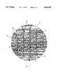
- FIG. 1 is a top view of an embodiment of the invention useful for a typical low density connector
- FIG. 2 is a top view of another embodiment of the invention useful for a typical high density connector
- FIG. 3 is a partial cut-away side view of the embodiment of FIG. 1 just prior to installation;
- FIG. 4 is a partial cut-away side view of the embodiment of FIG. 1 during installation but prior to full connector mating;
- FIG. 5 is a partial cut-away side view of the embodiment of FIG. 1 when installed and after full connector mating;
- FIG. 6 is a partial cut-away side view of the embodiment of FIG. 1 when installed but where no pin is installed;
- FIG. 7 is a top view of an embodiment of the invention useful for a DSUB25 connector
- FIG. 8 is a top view of an embodiment of the invention for watch electronics
- FIG. 9 is an exploded side cut-away view of the embodiment of FIG. 8;
- FIG. 10 is a side cut-away view of the embodiment of FIG. 8;
- FIG. 11 is a top view of a circuit suspended according to the present invention.
- FIG. 12 is a side view of the embodiment of FIG. 11;
- FIG. 13 is a perspective view of the embodiment of FIG. 11;
- FIG. 14 is a perspective view of the embodiment of FIG. 11 which has been somewhat contorted.
- FIG. 15 is a perspective view of the embodiment of FIG. 11 which has been contorted more than in FIG. 14.
- the preferred embodiments suspend electrical circuits in an insulative elastomeric body that changes shape, size, and volume during use, thereby providing the springiness required for electrical contacts, creating an environmental seal, or simply accommodating change of shape required during its use or installation, in addition to its electrical function.
- the preferred embodiment is essentially an insulative elastomeric body (e.g., silicone, RTV silicone, heat-cured silicone, two-part silicone, latex, rubber, clay, molding material, or other flexible or elastomeric materials) with an electrical circuit suspended within it (alternatively disposed on it), as will be further described.
- the transformable material freely suspends the electronics and interconnections, simultaneously providing: (1) mechanical interconnection and protection for all parts of the electrical circuit; (2) insulative properties; (3) a conformal coat for all parts of the electrical circuit, except interface connections which protrude from the transformable material; (4) a distensible and compressible environmental seal for the place where the device is installed (e.g., like a rubber gasket); and (5) a method for ensuring electrical contact from the invention (e.g., a "springinese" of the transformable material under compression to force protruding electrical contacts against corresponding external electrical contacts, such as pins).
- the present invention can literally be stretched, twisted, flexed, distended, and compressed as needed to install it in its host location or to fit in its host location, or to adapt to physical changes in the host location during use.
- the body may be any material that is non-conducting and transformable, i.e., flexible, and distensible and deformable under compression.
- Such materials include elastomers (such as silicone and latex) and formable and shapeable materials such as clay, gum, and foam-rubber.
- Interface protection consists of the need to isolate electrical equipment from both electrical and environmental factors such as electrical noise/transients and water/humidity respectively.
- This embodiment of the present invention is essentially a collection of electrical components wired together and suspended in an elastomeric material, shaped to fit snugly within a specific place (such as between a specific type of mating electrical connectors), with electrical contacts protruding from the elastomeric material to provide a reliable, re-usable connection to the outside world (like the selected pins and/or the shell of the connector) by using the elastomeric material to obtain the required "spring" force for the contacts.
- the present invention can be easily, and virtually instantly, added to any common connector to obtain electrical filtering, transient limiting, and an environmental seal. Since the present invention is flexible, twistable, distensible, and compressible, it readily adapts to normally unacceptable variations in the host location, such as pin misalignment, manufacturing tolerances, and manufacturer-to-manufacturer variations.
- Device 10 comprises a circular body 11, within which are contained openings 12, pin contacts 14, shell contacts 15, electrical components 16, and ground buses 18.
- Body 11 is preferably formed of silicone rubber or other elastomeric material.
- Openings 12 contain pin contacts 14, which are formed of any suitable conductor, such as 1 MIL to 10 MIL diameter copper wire (optionally plated with gold, tin, or silver), or flat wires such as 5 MIL ⁇ 1 MIL Au ribbon, or most preferably gold plated annealed copper wire (3 MIL diameter).
- Ground buses 18 interconnect electrical components 16, which may be capacitors (e.g., 0402 to 0603 chip capacitors), MOVs, diodes, shorting blocks, resistors, fuses, integrated circuits, memory storage devices, and the like. Ground buses 18 are preferably formed of 42 AWG Cu wire or 5 MIL ⁇ 1 MIL Au ribbon. Extra ground buses may be provided as needed for adequate RF performance of the device. Ground buses 18 electrically connect to the plug shell of the connector via shell contacts 15 which protrude slightly from the edge of body 11. Shell contacts 15 may be formed of materials identical to pin contacts 14.
- Slack sections 19 are preferably provided to ground buses 18 and pin contacts 14 so that electrical connections are not torn when body 11 is stretched, compressed, twisted, bent, or otherwise contorted. Individual electrical components are thereby permitted to move with respect to each other and with respect to the environment external to body 11.
- the invention may also be applied to a typical high density connector.
- Device 20 comprises a circular body 21, within which are contained openings 22, pin contacts 24, shell contacts 25, electrical components 26, ground buses 28, and slack sections 29.
- pin contacts 24 preferably are formed of 2-5 MIL Au plated Cu.
- FIG. 7 the invention may also be applied to a DSUB25 connector.
- Device 70 comprises an oblong body 71, within which are contained openings 72, pin contacts 74, shell contacts 75, electrical components 76, and ground buses 78.
- the invention can be practiced with any connector type, including Centronix, power plugs, and various plastic automotive connectors.
- FIGS. 3-5 illustrate the embodiment of FIG. 1 being installed between male and female connector assemblies, FIG. 3 showing the devices before installation, FIG. 4 during installation, and FIG. 5 after installation.
- the female connector assembly comprises receptacle shell 30, receptacle plastic 32, and socket 34.
- Male connector assembly comprises pin 40, plug shell 50, perimeter interfacial seal 52, plug interfacial seal 54, and plug plastic 56.
- the present invention's contacts are implemented by sizing the inner hole diameter of openings 12 in body 11 so that the inner hole diameter is 10% to 50% smaller than the diameter of pin 40 which passes through it upon installation. (However, openings may be made so small that it self closes via latent compressive forces in the silicone body. This is useful where one wants to maximize the contact force or where one must seal around and make contact to a pin or shell with a wide size variation.) Since the location of pins 40 changes with time due to external forces applied to the connector, there is no way to accurately know their positions at any given time. Thus, the as-built locations of pin openings 12 are in the general proximity of the pin locations, preferably not more than two pin diameters away.
- pin openings 12 In use (upon installation), the locations of pin openings 12 need not align with (and in practice usually will not align with) but self-adjust to obtain and maintain alignment with the ever changing locations of pins 40.
- pin contact 14 is forced against pin 40 by the compression of the body caused by a pin too big to fit into the opening unless the body compresses and the opening expands.
- Shell contacts 15 work on a similar basis to pin contacts 14, since the outer diameter or perimeter of body 11 is preferably 5% to 15% larger then the inner diameter of plug shell 50.
- FIG. 6 shows the position of a pin opening and contact after a connector pair is fully mated but without a pin installed in the opening. Note that the contact is pushed well into the space 42 normally occupied by the pin because the seal, under compression, is distended into areas under no, or less, compression.
- the contact concept of the present invention works even when a pin is severely misaligned or misplaced or even when a pin is temporarily bent well out of place. While existing devices will incur permanent damage due to major misalignments that frequently occur in practice during their installation, use and removal, the present invention accommodates these conditions by simply flexing into position as dictated by the pin location.
- Electrodes and wiring/interconnections within the elastomeric material seal are not constrained to any surface, plane, layer, or recess in a substrate as is the case with existing devices.
- the components can be anywhere and in any orientation within or on the elastomeric material, with the only constraint deriving from the need to maintain proper electrical isolation between adjacent components and interconnections. This results in a more efficient use of available space as well as relaxed manufacturing requirements.
- Interconnections can be accomplished by simple point-to-point wiring between components and pins, using solder, wire bonding, or conductive epoxy to bond wires to components.
- slack in wires or stretchable conductive silicone conductors may be used to permit maximum contortability of the device without tearing of electrical connections within the device. This freeform structure allows the transformability desired once the circuitry is suspended in the elastomeric material.
- the elastomeric material suspension system provides excellent mechanical isolation from vibration and mechanical shock for the suspended electrical circuitry, especially when compared with all existing devices which place the electrical circuitry and/or its substrate in intimate contact with hard surfaces of the connector.
- the present invention is installed into a connector that typically already has its pins installed (see FIG. 4).
- the present invention is installed by slipping it into the male connector, whereupon the pin openings shift positions (by deforming the elastomeric body) to accommodate out of alignment pins and the pin openings expand to accommodate the larger diameter of the pins and the outer diameter of the seal is compressed to fit within the smaller diameter of the connector shell.
- the present invention can be semi-permanently glued to the mating surface of the connector with, e.g., silicone rubber RTV, but this is not essential in that the device will stay in place without glue due to the forces exerted on the pins and the shell from the compression of the elastomeric material.
- This installation process is the same whether or not the connector has an existing interfacial (environmental) seal; the present invention will preserve the environmental seal for connectors that already have one and will create an environmental seal for connectors without one.
- the present invention may also be used to physically replace any elastomeric material component within a connector (or any other device), which will permit heightened functionality of the connector depending on the electrical circuitry within the body of the invention.
- a device according to the present invention may be installed in place of an elastomeric material component without any need for retooling.
- Perhaps the most evident elastomeric material components that may be so replaced are the seals in the back of male or female connectors and the plug interfacial seal of a male connector.
- the present invention is installed in the empty male connector shell, compressing the outer diameter of the seal.
- the seal be semi-permanently glued in place using a suitable glue, such as silicone rubber RTV. Later, when the pins are installed in the connector, they will expand the pin openings in the seal, again creating the required environmental seal and compression forces needed to activate the electrical contacts.
- each of the electrical components within the body of the invention is preferably an 0402 to 0603 chip capacitor.
- the body of the present invention is preferably clear so that the electrical components may be viewed within, which permits visual inspection (either human or automated) to determine certain faults.
- the body may be easily dyed any desired color by simply adding dye to the silicone, which permits color-coding of components for easy visual identification.
- the present invention can be used to perform a variety of electrical functions by simply changing the electrical circuitry contained within the device. For example, replacing the capacitors with diodes or metal oxide varistors (MOVs) in surface mount (SMT) form creates a transient limiting device useful to protect an electrical device from electrostatic discharge (ESD), lightning, and other common electrical transients.
- the invention may be used to free up valuable internal circuit board space of an electrical device by placing various parallel electrical interface components within the invention instead of on the internal circuit board. Since the space within the connector is typically thought of as wasted space, placing the components in the invention instead of on an internal circuit board may be more cost effective and/or may allow the host electrical device to be smaller.
- the present invention as a sensor for the voltage and current on pins within a connector.
- the invention can contain various sensing circuitry such as magnetoresistive current sensors, calibrated fuses or antifuses placed between pins and other pins or the connector shell, and/or other simple memory circuits as are commonly used (such as flip-flops, programmable gate arrays, etc.).
- sensing circuitry such as magnetoresistive current sensors, calibrated fuses or antifuses placed between pins and other pins or the connector shell, and/or other simple memory circuits as are commonly used (such as flip-flops, programmable gate arrays, etc.).
- the present invention may contain any combination of electrical components familiar to those skilled in the art as it exists now or in the future.
- the present invention can also be used advantageously as an alternative way to add electronics in "clamshell" type enclosures commonly used for products like watches, automobile key fobs, calculators, and the like.
- the advantages over traditional packaging include: (1) electronics and interconnects are environmentally sealed by virtue of being totally contained within the elastomeric material (preferably silicone); (2) a peripheral environmental seal for the housing can be achieved simply by compressing the elastomeric material between the two halves of the clamshell; (3) a circuit board is not needed; (4) thermal and mechanical isolation of electronics and interconnects is provided; and (5) contact means to the battery (and other separate components as required) can be achieved by using the compressive forces within the elastomeric material to provide the spring force needed to push these contacts together (eliminating the need for fragile spring metal contacts such as BeCu that typically perform this function).
- watch electronics may be conveniently packaged according to the present invention.
- the internal watch electronics includes semiconductor chip or die 80 and electrical interconnects 81 completely suspended in elastomeric material 82 (preferably silicone).
- Display 83 may be placed so that the display face is exposed, or if a transparent elastomeric material is used, totally contained within the elastomeric material.
- Switches 84 are partially exposed to allow proper operation.
- a recess is formed in the elastomeric material to removably accept battery 85.
- Electrical interconnects 81 may be of any suitable conductive material, such as copper or gold wire or traces.
- elastomeric materials such as silicone, or insulated wire
- Interconnects are illustrated with service loops to accommodate compression of the elastomeric material and the resulting small movement of connected electronic components with respect to each other.
- These electronics and elastomeric material comprise a complete subassembly which is shown placed onto the lower half of clamshell 86. The watch device prior to mating of the clamshells is shown in FIG. 9. An environmental seal for the enclosure is created when elastomeric material 82 is compressed around its perimeter by clamshell top 87 and bottom 86 as they are mated, as illustrated in FIG. 10.
- FIGS. 11-15 illustrate another device according to the present invention for packaging electronics.
- Device 100 comprises elastomeric material body 101 (preferably silicone) which suspends various electrical and electronic components 102 interconnected by conducting elements 103 with output and input connections obtained via contacts 104.
- Conducting elements 103 and contacts 104 are routed between components such that they contain residual slack, allowing the individual components to move with respect to each other as the elastomeric material body is stretched, flexed, compressed, and/or twisted during installation and use without damaging the interconnections or suspended components.
- FIGS. 14 and 15 show two exemplary deformations of the elastomeric material body that can be easily accommodated by the interconnecting means and components without damage.
- the elastomeric material body is undergoing both uneven flexure and unevenly applied compression at point 105. Note that the elastomeric material body can be completely clear, translucent, or opaque and can be dyed to any color desired during construction.
- Devices according to the invention are particularly useful for implanted medical devices, where small size, adaptable shape and size, and environmental sealing are simultaneously desired.
- the body of the device must be such that it can be placed in direct contact with many human and animal tissues, while isolating the internal components and conducting means from the tissues and vice versa. Silicone provides a material meeting these considerations.
- the device may be constructed to be soft, supple, and limber so as to cause the minimum discomfort and to remain unobtrusive after implantation.
- any circuit application which utilizes or requires a seal can benefit from the device of the present invention.
Landscapes
- Engineering & Computer Science (AREA)
- Manufacturing & Machinery (AREA)
- Microelectronics & Electronic Packaging (AREA)
- Connector Housings Or Holding Contact Members (AREA)
- Vehicle Body Suspensions (AREA)
- Multi-Conductor Connections (AREA)
- Coupling Device And Connection With Printed Circuit (AREA)
Priority Applications (9)
| Application Number | Priority Date | Filing Date | Title |
|---|---|---|---|
| US08/369,377 US5686697A (en) | 1995-01-06 | 1995-01-06 | Electrical circuit suspension system |
| CA002209660A CA2209660C (en) | 1995-01-06 | 1996-01-04 | Electrical circuit suspension system |
| PCT/US1996/000159 WO1996021245A1 (en) | 1995-01-06 | 1996-01-04 | Electrical circuit suspension system |
| AU46541/96A AU4654196A (en) | 1995-01-06 | 1996-01-04 | Electrical circuit suspension system |
| AT96902103T ATE272250T1 (de) | 1995-01-06 | 1996-01-04 | Aufhängungssystem für elektrische schaltung |
| EP96902103A EP0801815B1 (de) | 1995-01-06 | 1996-01-04 | Aufhängungssystem für elektrische schaltung |
| ES96902103T ES2225867T3 (es) | 1995-01-06 | 1996-01-04 | Sistema de suspension de circuitos electricos. |
| DE69633001T DE69633001T2 (de) | 1995-01-06 | 1996-01-04 | Aufhängungssystem für elektrische schaltung |
| US08/919,934 US6613979B1 (en) | 1995-01-06 | 1997-08-27 | Electrical circuit suspension system |
Applications Claiming Priority (1)
| Application Number | Priority Date | Filing Date | Title |
|---|---|---|---|
| US08/369,377 US5686697A (en) | 1995-01-06 | 1995-01-06 | Electrical circuit suspension system |
Related Child Applications (1)
| Application Number | Title | Priority Date | Filing Date |
|---|---|---|---|
| US08/919,934 Division US6613979B1 (en) | 1995-01-06 | 1997-08-27 | Electrical circuit suspension system |
Publications (1)
| Publication Number | Publication Date |
|---|---|
| US5686697A true US5686697A (en) | 1997-11-11 |
Family
ID=23455218
Family Applications (2)
| Application Number | Title | Priority Date | Filing Date |
|---|---|---|---|
| US08/369,377 Expired - Lifetime US5686697A (en) | 1995-01-06 | 1995-01-06 | Electrical circuit suspension system |
| US08/919,934 Expired - Fee Related US6613979B1 (en) | 1995-01-06 | 1997-08-27 | Electrical circuit suspension system |
Family Applications After (1)
| Application Number | Title | Priority Date | Filing Date |
|---|---|---|---|
| US08/919,934 Expired - Fee Related US6613979B1 (en) | 1995-01-06 | 1997-08-27 | Electrical circuit suspension system |
Country Status (8)
| Country | Link |
|---|---|
| US (2) | US5686697A (de) |
| EP (1) | EP0801815B1 (de) |
| AT (1) | ATE272250T1 (de) |
| AU (1) | AU4654196A (de) |
| CA (1) | CA2209660C (de) |
| DE (1) | DE69633001T2 (de) |
| ES (1) | ES2225867T3 (de) |
| WO (1) | WO1996021245A1 (de) |
Cited By (22)
| Publication number | Priority date | Publication date | Assignee | Title |
|---|---|---|---|---|
| US5889308A (en) * | 1996-08-09 | 1999-03-30 | Hyundai Electronics Industries Co., Ltd. | Semiconductor device having an electrostatic discharging protection circuit using a non-ohmic material |
| US6114856A (en) * | 1998-04-27 | 2000-09-05 | Benz Companies, Inc. | Method for detecting faults in electrical circuits having pin type connector |
| US6142831A (en) * | 1999-02-01 | 2000-11-07 | Aux Corporation | Multifunction connector assembly |
| US6175487B1 (en) | 1998-08-15 | 2001-01-16 | Nsi Enterprises, Inc. | Luminaire assembly |
| US20020100607A1 (en) * | 1999-01-13 | 2002-08-01 | Girard Mark T. | Electrical component and a shuntable/shunted electrical component and method for shunting and deshunting |
| US20020153162A1 (en) * | 2000-12-27 | 2002-10-24 | Sergio Spreafico | Superconducting cable |
| US6613979B1 (en) | 1995-01-06 | 2003-09-02 | Quell Corporation | Electrical circuit suspension system |
| US20040008459A1 (en) * | 2002-07-11 | 2004-01-15 | Siemens Westinghouse Power Corporation | Protected exciter for an electrical power generator and associated methods |
| US6779247B1 (en) * | 1999-10-01 | 2004-08-24 | Stmicroelectronics S.R.L. | Method of producing suspended elements for electrical connection between two portions of a micromechanism which can move relative to one another |
| US20040207964A1 (en) * | 2003-04-21 | 2004-10-21 | International Business Machines Corporation | ESD shorting block system and method for compression connector-type cables |
| US7561405B1 (en) | 2006-05-01 | 2009-07-14 | Bae Systems Land & Armaments, L.P. | Feed through capacitor |
| US20110092222A1 (en) * | 2009-10-20 | 2011-04-21 | Industrial Technology Research Institute | Vectoring service initiation system and method based on sensor assisted positioning |
| US20110133749A1 (en) * | 2008-06-12 | 2011-06-09 | Abb Technology Ag | Test arrangement for ac testing of electrical high voltage components |
| US20120086433A1 (en) * | 2010-10-06 | 2012-04-12 | Industrial Technology Research Institute | Mems-based current sensing apparatus |
| CN102455377A (zh) * | 2010-10-27 | 2012-05-16 | 财团法人工业技术研究院 | 微机电系统的电流感测装置 |
| US20130187635A1 (en) * | 2012-01-19 | 2013-07-25 | Industrial Technology Research Institute | Electrical sensor for a two-wire power cable |
| US20140130611A1 (en) * | 2008-11-14 | 2014-05-15 | Kulite Semiconductor Products, Inc. | Pressure transducer structures suitable for curved surfaces |
| JPWO2015199128A1 (ja) * | 2014-06-27 | 2017-07-13 | 日本電気株式会社 | 電子機器およびその製造方法 |
| US9756751B1 (en) | 2015-03-05 | 2017-09-05 | Lockheed Martin Corporation | Tunable vibration isolation system with integrated A-frame architecture for low phase noise radio frequency synthesizers |
| US20180003739A1 (en) * | 2016-06-30 | 2018-01-04 | The Regents Of The University Of Michigan | Plug-through power meter with planar profile |
| US10849212B2 (en) | 2018-05-15 | 2020-11-24 | Panasonic Avionics Corporation | Devices and systems for controlling electrostatic discharge on electronic devices |
| WO2020252678A1 (zh) | 2019-06-19 | 2020-12-24 | 韩宇南 | 滤波电缆 |
Families Citing this family (41)
| Publication number | Priority date | Publication date | Assignee | Title |
|---|---|---|---|---|
| TW504813B (en) * | 2001-11-09 | 2002-10-01 | Advanced Semiconductor Eng | Packaging board having electrostatic discharge protection |
| TWI279894B (en) * | 2001-11-14 | 2007-04-21 | Advanced Semiconductor Eng | Package substrate having electrostatic discharge protection mechanism |
| TW504815B (en) * | 2001-11-16 | 2002-10-01 | Advanced Semiconductor Eng | Packaging mold device with ESD protection |
| US7491892B2 (en) * | 2003-03-28 | 2009-02-17 | Princeton University | Stretchable and elastic interconnects |
| US7465678B2 (en) * | 2003-03-28 | 2008-12-16 | The Trustees Of Princeton University | Deformable organic devices |
| US8217381B2 (en) | 2004-06-04 | 2012-07-10 | The Board Of Trustees Of The University Of Illinois | Controlled buckling structures in semiconductor interconnects and nanomembranes for stretchable electronics |
| US7521292B2 (en) | 2004-06-04 | 2009-04-21 | The Board Of Trustees Of The University Of Illinois | Stretchable form of single crystal silicon for high performance electronics on rubber substrates |
| KR101260981B1 (ko) | 2004-06-04 | 2013-05-10 | 더 보오드 오브 트러스티스 오브 더 유니버시티 오브 일리노이즈 | 인쇄가능한 반도체소자들의 제조 및 조립방법과 장치 |
| EP2255378B1 (de) | 2008-03-05 | 2015-08-05 | The Board of Trustees of the University of Illinois | Streckbare und klappbare elektronische anordnungen |
| JP5511155B2 (ja) * | 2008-06-25 | 2014-06-04 | パナソニック株式会社 | インターポーザ基板とその製造方法 |
| JP5646492B2 (ja) | 2008-10-07 | 2014-12-24 | エムシー10 インコーポレイテッドMc10,Inc. | 伸縮可能な集積回路およびセンサアレイを有する装置 |
| US8372726B2 (en) | 2008-10-07 | 2013-02-12 | Mc10, Inc. | Methods and applications of non-planar imaging arrays |
| US8097926B2 (en) | 2008-10-07 | 2012-01-17 | Mc10, Inc. | Systems, methods, and devices having stretchable integrated circuitry for sensing and delivering therapy |
| US8389862B2 (en) | 2008-10-07 | 2013-03-05 | Mc10, Inc. | Extremely stretchable electronics |
| US8886334B2 (en) | 2008-10-07 | 2014-11-11 | Mc10, Inc. | Systems, methods, and devices using stretchable or flexible electronics for medical applications |
| JP5689066B2 (ja) * | 2008-11-12 | 2015-03-25 | エムシー10 インコーポレイテッドMc10,Inc. | 高度に伸縮可能な電子部品 |
| TWI573185B (zh) | 2009-05-12 | 2017-03-01 | 美國伊利諾大學理事會 | 用於可變形及半透明顯示器之超薄微刻度無機發光二極體之印刷總成 |
| WO2011041727A1 (en) | 2009-10-01 | 2011-04-07 | Mc10, Inc. | Protective cases with integrated electronics |
| US8547710B2 (en) | 2009-10-16 | 2013-10-01 | Emprimus, Llc | Electromagnetically shielded power module |
| US8642900B2 (en) * | 2009-10-16 | 2014-02-04 | Emprimus, Llc | Modular electromagnetically shielded enclosure |
| US9936574B2 (en) | 2009-12-16 | 2018-04-03 | The Board Of Trustees Of The University Of Illinois | Waterproof stretchable optoelectronics |
| WO2011115643A1 (en) | 2010-03-17 | 2011-09-22 | The Board Of Trustees Of The University Of Illinois | Implantable biomedical devices on bioresorbable substrates |
| US8760859B2 (en) | 2010-05-03 | 2014-06-24 | Emprimus, Llc | Electromagnetically-shielded portable storage device |
| US8599576B2 (en) | 2010-10-29 | 2013-12-03 | Emprimus, Llc | Electromagnetically-protected electronic equipment |
| US8754980B2 (en) | 2010-11-05 | 2014-06-17 | Emprimus, Llc | Electromagnetically shielded camera and shielded enclosure for image capture devices |
| US8643772B2 (en) | 2010-11-05 | 2014-02-04 | Emprimus, Llc | Electromagnetically shielded video camera and shielded enclosure for image capture devices |
| US9420219B2 (en) | 2010-12-20 | 2016-08-16 | Emprimus, Llc | Integrated security video and electromagnetic pulse detector |
| US9093755B2 (en) | 2010-12-20 | 2015-07-28 | Emprimus, Llc | Lower power localized distributed radio frequency transmitter |
| US8202124B1 (en) * | 2011-03-11 | 2012-06-19 | Lear Corporation | Contact and receptacle assembly for a vehicle charging inlet |
| WO2012139024A1 (en) | 2011-04-06 | 2012-10-11 | Emprimus, Inc. | Electromagnetically- shielded optical imaging system |
| US9765934B2 (en) | 2011-05-16 | 2017-09-19 | The Board Of Trustees Of The University Of Illinois | Thermally managed LED arrays assembled by printing |
| KR102000302B1 (ko) | 2011-05-27 | 2019-07-15 | 엠씨10, 인크 | 전자, 광학, 및/또는 기계 장치 및 시스템, 그리고 이를 제조하기 위한 방법 |
| WO2013089867A2 (en) | 2011-12-01 | 2013-06-20 | The Board Of Trustees Of The University Of Illinois | Transient devices designed to undergo programmable transformations |
| US9171794B2 (en) | 2012-10-09 | 2015-10-27 | Mc10, Inc. | Embedding thin chips in polymer |
| US9642290B2 (en) | 2013-03-14 | 2017-05-02 | Emprimus, Llc | Electromagnetically protected electronic enclosure |
| US9327965B2 (en) | 2013-03-15 | 2016-05-03 | Versana Micro Inc | Transportation device having a monolithically integrated multi-sensor device on a semiconductor substrate and method therefor |
| US10491787B2 (en) | 2014-09-23 | 2019-11-26 | Flir Systems, Inc. | Electrostatic discharge mitigation systems and methods for imaging devices |
| US10925543B2 (en) | 2015-11-11 | 2021-02-23 | The Board Of Trustees Of The University Of Illinois | Bioresorbable silicon electronics for transient implants |
| US9930780B1 (en) | 2016-11-22 | 2018-03-27 | Lear Corporation | Remote control device having motherboard and battery daughterboard connected by interconnect |
| US12597743B2 (en) | 2023-05-08 | 2026-04-07 | Rolls-Royce Corporation | Variable length wire harness for electronic devices |
| US20250328174A1 (en) * | 2024-04-17 | 2025-10-23 | Dell Products L.P. | Hyperbaric thermal architecture for an information handling system |
Citations (32)
| Publication number | Priority date | Publication date | Assignee | Title |
|---|---|---|---|---|
| US2450528A (en) * | 1944-12-18 | 1948-10-05 | H H Buggie & Company | Electrical connector |
| US2451516A (en) * | 1945-07-14 | 1948-10-19 | Skobel Max | Seal terminal |
| US3004170A (en) * | 1958-12-24 | 1961-10-10 | Greenspan Arnold | Automobile theft protection device |
| US3086188A (en) * | 1962-01-18 | 1963-04-16 | Joseph I Ross | Non-reversing hermaphroditic cable connectors |
| US3569915A (en) * | 1968-09-16 | 1971-03-09 | Itt | Grounding foil |
| US3670292A (en) * | 1970-01-29 | 1972-06-13 | Itt | Grounding foil for electrical connectors |
| US3780352A (en) * | 1968-06-25 | 1973-12-18 | J Redwanz | Semiconductor interconnecting system using conductive patterns bonded to thin flexible insulating films |
| US3825874A (en) * | 1973-07-05 | 1974-07-23 | Itt | Electrical connector |
| US3852700A (en) * | 1969-04-18 | 1974-12-03 | Breston M | Grounding base for connector |
| US3905013A (en) * | 1973-04-27 | 1975-09-09 | Lee Maw Huei | Headlight warning system |
| US4056299A (en) * | 1976-05-03 | 1977-11-01 | Burroughs Corporation | Electrical connector |
| US4362350A (en) * | 1980-06-09 | 1982-12-07 | International Telephone And Telegraph Corporation | Contact retention assembly |
| US4407552A (en) * | 1978-05-18 | 1983-10-04 | Matsushita Electric Industrial Co., Ltd. | Connector unit |
| US4435740A (en) * | 1981-10-30 | 1984-03-06 | International Business Machines Corporation | Electric circuit packaging member |
| US4440463A (en) * | 1981-10-26 | 1984-04-03 | The Bendix Corporation | Electrical connector having a metallized plastic grounding insert |
| US4629269A (en) * | 1977-10-25 | 1986-12-16 | Allied Corporation | Electrical connector with environmental seal |
| US4703984A (en) * | 1985-10-28 | 1987-11-03 | Burroughs Corporation | Flexible access connector with miniature slotted pads |
| US4729743A (en) * | 1985-07-26 | 1988-03-08 | Amp Incorporated | Filtered electrical connector |
| US4820174A (en) * | 1986-08-06 | 1989-04-11 | Amp Incorporated | Modular connector assembly and filtered insert therefor |
| US4954089A (en) * | 1984-01-18 | 1990-09-04 | Methode Electronics, Inc. | Terminator assembly for interconnecting computer devices |
| US4979904A (en) * | 1990-01-16 | 1990-12-25 | Litton Systems, Inc. | Grounding disc |
| US4993964A (en) * | 1989-04-18 | 1991-02-19 | Martin Marietta Corporation | Electrical connector environmental sealing plug |
| US5014162A (en) * | 1989-06-27 | 1991-05-07 | At&T Bell Laboratories | Solder assembly of components |
| US5092788A (en) * | 1990-12-03 | 1992-03-03 | Motorola, Inc. | Self-contained universal accessory connector and seal |
| US5112253A (en) * | 1991-08-15 | 1992-05-12 | Amphenol Corporation | Arrangement for removably mounting a transient suppression or electrical filter device in an electrical connector |
| US5134252A (en) * | 1990-01-21 | 1992-07-28 | Sony Corporation | Signal line |
| US5149274A (en) * | 1991-04-01 | 1992-09-22 | Amphenol Corporation | Electrical connector with combined circuits |
| US5181859A (en) * | 1991-04-29 | 1993-01-26 | Trw Inc. | Electrical connector circuit wafer |
| US5183698A (en) * | 1991-03-07 | 1993-02-02 | G & H Technology, Inc. | Electrical overstress pulse protection |
| US5194010A (en) * | 1992-01-22 | 1993-03-16 | Molex Incorporated | Surface mount electrical connector assembly |
| US5220488A (en) * | 1985-09-04 | 1993-06-15 | Ufe Incorporated | Injection molded printed circuits |
| US5241454A (en) * | 1992-01-22 | 1993-08-31 | International Business Machines Corporation | Mutlilayered flexible circuit package |
Family Cites Families (11)
| Publication number | Priority date | Publication date | Assignee | Title |
|---|---|---|---|---|
| GB1204795A (en) * | 1968-03-29 | 1970-09-09 | Muirhead Ltd | Improvements in packaging circuitry |
| DE1932380A1 (de) * | 1969-06-26 | 1971-01-07 | Licentia Gmbh | Schaltungsaufbau |
| US3827056A (en) * | 1972-10-04 | 1974-07-30 | Alden Res Found | Graphic electric recorder scanning device with printed recording strips |
| US3851859A (en) * | 1973-06-04 | 1974-12-03 | J Karp | Apparatus for mixing clay |
| JPS5521162A (en) * | 1978-08-01 | 1980-02-15 | Nec Corp | High tension semiconductor device |
| US4918814A (en) * | 1984-12-20 | 1990-04-24 | Redmond John P | Process of making a layered elastomeric connector |
| JPH04206179A (ja) * | 1990-11-29 | 1992-07-28 | Fuji Facom Corp | プリント基板内蔵コネクタ |
| EP0579775B1 (de) * | 1991-12-11 | 1995-08-23 | L.A.Gear, Inc. | Sportschuh mit einsteckbarem modul |
| US5226220A (en) * | 1991-12-19 | 1993-07-13 | Allied-Signal Inc. | Method of making a strain relief for magnetic device lead wires |
| DE4303583C2 (de) * | 1993-02-08 | 1996-02-22 | Alpha Beta Electronics Ag | Ventil mit einer Einrichtung zur Erzeugung eines drahtlos übermittelbaren Druckabnahme-Anzeigesignals für Fahrzeugreifen |
| US5686697A (en) | 1995-01-06 | 1997-11-11 | Metatech Corporation | Electrical circuit suspension system |
-
1995
- 1995-01-06 US US08/369,377 patent/US5686697A/en not_active Expired - Lifetime
-
1996
- 1996-01-04 AU AU46541/96A patent/AU4654196A/en not_active Abandoned
- 1996-01-04 CA CA002209660A patent/CA2209660C/en not_active Expired - Fee Related
- 1996-01-04 ES ES96902103T patent/ES2225867T3/es not_active Expired - Lifetime
- 1996-01-04 DE DE69633001T patent/DE69633001T2/de not_active Expired - Lifetime
- 1996-01-04 AT AT96902103T patent/ATE272250T1/de not_active IP Right Cessation
- 1996-01-04 EP EP96902103A patent/EP0801815B1/de not_active Expired - Lifetime
- 1996-01-04 WO PCT/US1996/000159 patent/WO1996021245A1/en not_active Ceased
-
1997
- 1997-08-27 US US08/919,934 patent/US6613979B1/en not_active Expired - Fee Related
Patent Citations (33)
| Publication number | Priority date | Publication date | Assignee | Title |
|---|---|---|---|---|
| US2450528A (en) * | 1944-12-18 | 1948-10-05 | H H Buggie & Company | Electrical connector |
| US2451516A (en) * | 1945-07-14 | 1948-10-19 | Skobel Max | Seal terminal |
| US3004170A (en) * | 1958-12-24 | 1961-10-10 | Greenspan Arnold | Automobile theft protection device |
| US3086188A (en) * | 1962-01-18 | 1963-04-16 | Joseph I Ross | Non-reversing hermaphroditic cable connectors |
| US3780352A (en) * | 1968-06-25 | 1973-12-18 | J Redwanz | Semiconductor interconnecting system using conductive patterns bonded to thin flexible insulating films |
| US3569915A (en) * | 1968-09-16 | 1971-03-09 | Itt | Grounding foil |
| US3852700A (en) * | 1969-04-18 | 1974-12-03 | Breston M | Grounding base for connector |
| US3670292A (en) * | 1970-01-29 | 1972-06-13 | Itt | Grounding foil for electrical connectors |
| US3905013A (en) * | 1973-04-27 | 1975-09-09 | Lee Maw Huei | Headlight warning system |
| US3825874A (en) * | 1973-07-05 | 1974-07-23 | Itt | Electrical connector |
| US4056299A (en) * | 1976-05-03 | 1977-11-01 | Burroughs Corporation | Electrical connector |
| US4629269A (en) * | 1977-10-25 | 1986-12-16 | Allied Corporation | Electrical connector with environmental seal |
| US4407552A (en) * | 1978-05-18 | 1983-10-04 | Matsushita Electric Industrial Co., Ltd. | Connector unit |
| US4362350A (en) * | 1980-06-09 | 1982-12-07 | International Telephone And Telegraph Corporation | Contact retention assembly |
| US4440463A (en) * | 1981-10-26 | 1984-04-03 | The Bendix Corporation | Electrical connector having a metallized plastic grounding insert |
| US4435740A (en) * | 1981-10-30 | 1984-03-06 | International Business Machines Corporation | Electric circuit packaging member |
| US4954089A (en) * | 1984-01-18 | 1990-09-04 | Methode Electronics, Inc. | Terminator assembly for interconnecting computer devices |
| US4729743A (en) * | 1985-07-26 | 1988-03-08 | Amp Incorporated | Filtered electrical connector |
| US5220488A (en) * | 1985-09-04 | 1993-06-15 | Ufe Incorporated | Injection molded printed circuits |
| US4703984A (en) * | 1985-10-28 | 1987-11-03 | Burroughs Corporation | Flexible access connector with miniature slotted pads |
| US4820174A (en) * | 1986-08-06 | 1989-04-11 | Amp Incorporated | Modular connector assembly and filtered insert therefor |
| US4993964A (en) * | 1989-04-18 | 1991-02-19 | Martin Marietta Corporation | Electrical connector environmental sealing plug |
| US5014162A (en) * | 1989-06-27 | 1991-05-07 | At&T Bell Laboratories | Solder assembly of components |
| US4979904A (en) * | 1990-01-16 | 1990-12-25 | Litton Systems, Inc. | Grounding disc |
| US5134252A (en) * | 1990-01-21 | 1992-07-28 | Sony Corporation | Signal line |
| US5092788A (en) * | 1990-12-03 | 1992-03-03 | Motorola, Inc. | Self-contained universal accessory connector and seal |
| US5183698A (en) * | 1991-03-07 | 1993-02-02 | G & H Technology, Inc. | Electrical overstress pulse protection |
| US5149274A (en) * | 1991-04-01 | 1992-09-22 | Amphenol Corporation | Electrical connector with combined circuits |
| US5181859A (en) * | 1991-04-29 | 1993-01-26 | Trw Inc. | Electrical connector circuit wafer |
| US5290191A (en) * | 1991-04-29 | 1994-03-01 | Foreman Kevin G | Interface conditioning insert wafer |
| US5112253A (en) * | 1991-08-15 | 1992-05-12 | Amphenol Corporation | Arrangement for removably mounting a transient suppression or electrical filter device in an electrical connector |
| US5194010A (en) * | 1992-01-22 | 1993-03-16 | Molex Incorporated | Surface mount electrical connector assembly |
| US5241454A (en) * | 1992-01-22 | 1993-08-31 | International Business Machines Corporation | Mutlilayered flexible circuit package |
Cited By (27)
| Publication number | Priority date | Publication date | Assignee | Title |
|---|---|---|---|---|
| US6613979B1 (en) | 1995-01-06 | 2003-09-02 | Quell Corporation | Electrical circuit suspension system |
| US5889308A (en) * | 1996-08-09 | 1999-03-30 | Hyundai Electronics Industries Co., Ltd. | Semiconductor device having an electrostatic discharging protection circuit using a non-ohmic material |
| US6114856A (en) * | 1998-04-27 | 2000-09-05 | Benz Companies, Inc. | Method for detecting faults in electrical circuits having pin type connector |
| US6175487B1 (en) | 1998-08-15 | 2001-01-16 | Nsi Enterprises, Inc. | Luminaire assembly |
| US20020100607A1 (en) * | 1999-01-13 | 2002-08-01 | Girard Mark T. | Electrical component and a shuntable/shunted electrical component and method for shunting and deshunting |
| US6846991B2 (en) | 1999-01-13 | 2005-01-25 | Applied Kinetics, Inc. | Electrical component and a shuntable/shunted electrical component and method for shunting and deshunting |
| US6142831A (en) * | 1999-02-01 | 2000-11-07 | Aux Corporation | Multifunction connector assembly |
| US6779247B1 (en) * | 1999-10-01 | 2004-08-24 | Stmicroelectronics S.R.L. | Method of producing suspended elements for electrical connection between two portions of a micromechanism which can move relative to one another |
| US20020153162A1 (en) * | 2000-12-27 | 2002-10-24 | Sergio Spreafico | Superconducting cable |
| US6891706B2 (en) * | 2002-07-11 | 2005-05-10 | Siemens Westinghouse Power Corporation | Protected exciter for an electrical power generator and associated methods |
| US20040008459A1 (en) * | 2002-07-11 | 2004-01-15 | Siemens Westinghouse Power Corporation | Protected exciter for an electrical power generator and associated methods |
| US7199992B2 (en) * | 2003-04-21 | 2007-04-03 | International Business Machines Corporation | ESD shorting block system and method for compression connector-type cables |
| US20040207964A1 (en) * | 2003-04-21 | 2004-10-21 | International Business Machines Corporation | ESD shorting block system and method for compression connector-type cables |
| US7561405B1 (en) | 2006-05-01 | 2009-07-14 | Bae Systems Land & Armaments, L.P. | Feed through capacitor |
| US20110133749A1 (en) * | 2008-06-12 | 2011-06-09 | Abb Technology Ag | Test arrangement for ac testing of electrical high voltage components |
| US10048139B2 (en) * | 2008-11-14 | 2018-08-14 | Kulite Semiconductor Products, Inc. | Pressure transducer structures suitable for curved surfaces |
| US20140130611A1 (en) * | 2008-11-14 | 2014-05-15 | Kulite Semiconductor Products, Inc. | Pressure transducer structures suitable for curved surfaces |
| US20110092222A1 (en) * | 2009-10-20 | 2011-04-21 | Industrial Technology Research Institute | Vectoring service initiation system and method based on sensor assisted positioning |
| US20120086433A1 (en) * | 2010-10-06 | 2012-04-12 | Industrial Technology Research Institute | Mems-based current sensing apparatus |
| CN102455377A (zh) * | 2010-10-27 | 2012-05-16 | 财团法人工业技术研究院 | 微机电系统的电流感测装置 |
| US20130187635A1 (en) * | 2012-01-19 | 2013-07-25 | Industrial Technology Research Institute | Electrical sensor for a two-wire power cable |
| US8970206B2 (en) * | 2012-01-19 | 2015-03-03 | Industrial Technology Research Institute | Electrical sensor for a two-wire power cable |
| JPWO2015199128A1 (ja) * | 2014-06-27 | 2017-07-13 | 日本電気株式会社 | 電子機器およびその製造方法 |
| US9756751B1 (en) | 2015-03-05 | 2017-09-05 | Lockheed Martin Corporation | Tunable vibration isolation system with integrated A-frame architecture for low phase noise radio frequency synthesizers |
| US20180003739A1 (en) * | 2016-06-30 | 2018-01-04 | The Regents Of The University Of Michigan | Plug-through power meter with planar profile |
| US10849212B2 (en) | 2018-05-15 | 2020-11-24 | Panasonic Avionics Corporation | Devices and systems for controlling electrostatic discharge on electronic devices |
| WO2020252678A1 (zh) | 2019-06-19 | 2020-12-24 | 韩宇南 | 滤波电缆 |
Also Published As
| Publication number | Publication date |
|---|---|
| US6613979B1 (en) | 2003-09-02 |
| ATE272250T1 (de) | 2004-08-15 |
| AU4654196A (en) | 1996-07-24 |
| EP0801815A4 (de) | 1998-08-19 |
| ES2225867T3 (es) | 2005-03-16 |
| WO1996021245A1 (en) | 1996-07-11 |
| EP0801815B1 (de) | 2004-07-28 |
| CA2209660A1 (en) | 1996-07-11 |
| CA2209660C (en) | 2001-12-18 |
| EP0801815A1 (de) | 1997-10-22 |
| DE69633001T2 (de) | 2005-08-04 |
| DE69633001D1 (de) | 2004-09-02 |
Similar Documents
| Publication | Publication Date | Title |
|---|---|---|
| US5686697A (en) | Electrical circuit suspension system | |
| US5530622A (en) | Electronic assembly for connecting to an electronic system and method of manufacture thereof | |
| US7682159B2 (en) | Electrical connector and camera device having the same | |
| EP2916392B1 (de) | Durchführungssteckverbinder für hermetisch abgedichtete elektronische vorrichtungen | |
| EP3067992B1 (de) | Elektrisches Verbinderkit, elektronisches Bauteil und Montageverfahren | |
| US7708566B2 (en) | Electrical connector with integrated circuit bonded thereon | |
| US6392887B1 (en) | PLGA-BGA socket using elastomer connectors | |
| TW202109995A (zh) | 加固之電插座 | |
| US9356405B1 (en) | Connector tongue element for an electrical connector plug receptacle and a method for producing the same | |
| EP1204167A1 (de) | Rosterverbinder | |
| JP3318567B2 (ja) | コネクタ | |
| CN119209142A (zh) | 混合spe连接器单元 | |
| KR20200099023A (ko) | 고속 데이터 및 고전력 전송이 향상된 리셉터클 커넥터 | |
| US4820203A (en) | Multicontact connector | |
| US20220294167A1 (en) | Method for manufacturing data transmission apparatus and data transmission apparatus | |
| US6002595A (en) | Cable-to-board assemblies | |
| JPH06338366A (ja) | ツーピースコネクタ | |
| JPS60250573A (ja) | 電気接続用ソケツト | |
| JPH06309522A (ja) | Icカード | |
| JPH04214663A (ja) | 半導体集積回路装置 |
Legal Events
| Date | Code | Title | Description |
|---|---|---|---|
| AS | Assignment |
Owner name: METATECH CORPORATION, A CA CORP., CALIFORNIA Free format text: ASSIGNMENT OF ASSIGNORS INTEREST;ASSIGNORS:MILLER, PAUL J.;FOREMAN, KEVIN G.;REEL/FRAME:007311/0537 Effective date: 19950106 |
|
| STCF | Information on status: patent grant |
Free format text: PATENTED CASE |
|
| FPAY | Fee payment |
Year of fee payment: 4 |
|
| AS | Assignment |
Owner name: QUELL CORPORATION, NEW MEXICO Free format text: ASSIGNMENT OF ASSIGNORS INTEREST;ASSIGNOR:METATECH CORPORATION;REEL/FRAME:013879/0944 Effective date: 20030121 |
|
| FPAY | Fee payment |
Year of fee payment: 8 |
|
| FPAY | Fee payment |
Year of fee payment: 12 |