US5650806A - Ink jet nozzle/valve, pen and printer - Google Patents
Ink jet nozzle/valve, pen and printer Download PDFInfo
- Publication number
- US5650806A US5650806A US08/349,701 US34970194A US5650806A US 5650806 A US5650806 A US 5650806A US 34970194 A US34970194 A US 34970194A US 5650806 A US5650806 A US 5650806A
- Authority
- US
- United States
- Prior art keywords
- ink
- elastic material
- orifice
- jet printer
- ink jet
- Prior art date
- Legal status (The legal status is an assumption and is not a legal conclusion. Google has not performed a legal analysis and makes no representation as to the accuracy of the status listed.)
- Expired - Fee Related
Links
Images


Classifications
-
- B—PERFORMING OPERATIONS; TRANSPORTING
- B41—PRINTING; LINING MACHINES; TYPEWRITERS; STAMPS
- B41J—TYPEWRITERS; SELECTIVE PRINTING MECHANISMS, i.e. MECHANISMS PRINTING OTHERWISE THAN FROM A FORME; CORRECTION OF TYPOGRAPHICAL ERRORS
- B41J2/00—Typewriters or selective printing mechanisms characterised by the printing or marking process for which they are designed
- B41J2/005—Typewriters or selective printing mechanisms characterised by the printing or marking process for which they are designed characterised by bringing liquid or particles selectively into contact with a printing material
- B41J2/01—Ink jet
- B41J2/135—Nozzles
- B41J2/14—Structure thereof only for on-demand ink jet heads
-
- B—PERFORMING OPERATIONS; TRANSPORTING
- B41—PRINTING; LINING MACHINES; TYPEWRITERS; STAMPS
- B41J—TYPEWRITERS; SELECTIVE PRINTING MECHANISMS, i.e. MECHANISMS PRINTING OTHERWISE THAN FROM A FORME; CORRECTION OF TYPOGRAPHICAL ERRORS
- B41J2/00—Typewriters or selective printing mechanisms characterised by the printing or marking process for which they are designed
- B41J2/005—Typewriters or selective printing mechanisms characterised by the printing or marking process for which they are designed characterised by bringing liquid or particles selectively into contact with a printing material
- B41J2/01—Ink jet
- B41J2/015—Ink jet characterised by the jet generation process
- B41J2/04—Ink jet characterised by the jet generation process generating single droplets or particles on demand
-
- B—PERFORMING OPERATIONS; TRANSPORTING
- B41—PRINTING; LINING MACHINES; TYPEWRITERS; STAMPS
- B41J—TYPEWRITERS; SELECTIVE PRINTING MECHANISMS, i.e. MECHANISMS PRINTING OTHERWISE THAN FROM A FORME; CORRECTION OF TYPOGRAPHICAL ERRORS
- B41J2/00—Typewriters or selective printing mechanisms characterised by the printing or marking process for which they are designed
- B41J2/005—Typewriters or selective printing mechanisms characterised by the printing or marking process for which they are designed characterised by bringing liquid or particles selectively into contact with a printing material
- B41J2/01—Ink jet
- B41J2/135—Nozzles
- B41J2/14—Structure thereof only for on-demand ink jet heads
- B41J2/14201—Structure of print heads with piezoelectric elements
- B41J2/14233—Structure of print heads with piezoelectric elements of film type, deformed by bending and disposed on a diaphragm
-
- B—PERFORMING OPERATIONS; TRANSPORTING
- B41—PRINTING; LINING MACHINES; TYPEWRITERS; STAMPS
- B41J—TYPEWRITERS; SELECTIVE PRINTING MECHANISMS, i.e. MECHANISMS PRINTING OTHERWISE THAN FROM A FORME; CORRECTION OF TYPOGRAPHICAL ERRORS
- B41J2/00—Typewriters or selective printing mechanisms characterised by the printing or marking process for which they are designed
- B41J2/005—Typewriters or selective printing mechanisms characterised by the printing or marking process for which they are designed characterised by bringing liquid or particles selectively into contact with a printing material
- B41J2/01—Ink jet
- B41J2/135—Nozzles
- B41J2/14—Structure thereof only for on-demand ink jet heads
- B41J2002/14379—Edge shooter
-
- B—PERFORMING OPERATIONS; TRANSPORTING
- B41—PRINTING; LINING MACHINES; TYPEWRITERS; STAMPS
- B41J—TYPEWRITERS; SELECTIVE PRINTING MECHANISMS, i.e. MECHANISMS PRINTING OTHERWISE THAN FROM A FORME; CORRECTION OF TYPOGRAPHICAL ERRORS
- B41J2/00—Typewriters or selective printing mechanisms characterised by the printing or marking process for which they are designed
- B41J2/005—Typewriters or selective printing mechanisms characterised by the printing or marking process for which they are designed characterised by bringing liquid or particles selectively into contact with a printing material
- B41J2/01—Ink jet
- B41J2/135—Nozzles
- B41J2/14—Structure thereof only for on-demand ink jet heads
- B41J2002/14491—Electrical connection
-
- B—PERFORMING OPERATIONS; TRANSPORTING
- B41—PRINTING; LINING MACHINES; TYPEWRITERS; STAMPS
- B41J—TYPEWRITERS; SELECTIVE PRINTING MECHANISMS, i.e. MECHANISMS PRINTING OTHERWISE THAN FROM A FORME; CORRECTION OF TYPOGRAPHICAL ERRORS
- B41J2202/00—Embodiments of or processes related to ink-jet or thermal heads
- B41J2202/01—Embodiments of or processes related to ink-jet heads
- B41J2202/05—Heads having a valve
Definitions
- High speed ink jet printers are usually of the so called "continuous type" in which a stream of ink droplets is continuously emitted from a nozzle, the droplets which are to be printed being charged and then deflected to a chosen print position by electrostatic forces, and droplets which are not required robe printed passing directly to a gutter and being recirculated.
- the control mechanisms for such continuous ink jet printers are therefore complicated and, as a direct consequence, the selling price of a single printhead continuous ink jet printer is very high in comparison with that of a drop-on-demand printer.
- Such printers are typically used to produce small characters or rows of characters generally less than about 5 mm in height. Increasing the number of nozzles in order to produce larger characters, inevitably further complicates the control mechanism.
- a variety of means are employed in the construction of pens and similar writing instruments for depositing ink on the writing surface, but a general requirement is that a fine and uniform line be produced with great consistency and low writing pressure.
- the present invention has the object of providing a nozzle which is usable in both printers and pens to provide the particular requirements of both.
- a combined nozzle and valve for an ink jet printer or writing instrument having an orifice in an elastic material, the orifice being pre-loaded in compression to cause the orifice to be normally sealed, and a slit or hole in the elastic material, the elastic material being pre-loaded in compression to cause the orifice to be normally sealed, and controllably deformable to cause the orifice to open.
- the ink jet printer has an ink chamber for containing ink, the nozzle/valve being formed in a wall of the chamber, through which a jet of ink is issued in use for printing on a surface; and, an actuator engaging the elastic material and operable to cause it to deform so as to open or close the slit or hole.
- the orifice in the elastic material is tapered to reduce loss of head through viscous drag effects, the minimum cross-section of the orifice being provided at the outer surface of the elastic material and the profile of the taper being designed appropriately.
- the orifice is able to be positively closed when it is not passing ink and this will prevent or reduce the drying of ink in the orifice and clogging of it with ink pigment.
- the ink jet may open the orifice from the inside to the outside, and because a taper may be provided to ensure low viscous losses, the full driving pressure is substantially instantly available at the orifice when the printer is switched on. This is significant, for a low ink flow rate will produce overflow which generates an ink drop on the outer face of the elastic wall which obscures the orifice. This drop not only impedes the formation of a stable jet, but may also influence the initial direction of the jet or even inhibit jet formation entirely.
- FIG. 8 shows an embodiment of a pen using the nozzle of the invention
- FIG. 11 is a plan view of the third printhead on a smaller scale.
- FIGS. 1 and 2 An embodiment of an ink jet printer, with valve closure by ink pressure, is shown in orthogonal sections through the printhead axis in FIGS. 1 and 2.
- the rubber component, 1 comprises a rigid cylindrical section containing the pressurised ink, 2, and integral conical end plug, 3. This is transected by a linearly tapering slit, 4, the outer aspect of which forms the orifice, 5.
- a rigid ring-like component forms the actuator, 6. Without load on the actuator, ink pressure forces the conical end plug to dish outwards, so sealing the slit. Pressure on the actuator against the end plug causes tension on the conical inner face which results in opening of the slit system. The opened slit is illustrated in FIG. 3.
- the actuator may be driven by magnetic elements or, when used in a pen, manually.
- FIGS. 4 and 5 illustrate a longitudinal and transverse section respectively through a printhead having an array of nozzles.
- the rubber component 7 connects with a pressurised ink feed 8 and contains an array of nozzles in the form of tapered slits 9.
- the slits may conveniently be formed by transfixing the rubber component with a comb of piercing blades introduced through the ink feed 8.
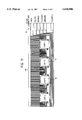
- the printhead has a main body part 11 which may be formed, for example, of brass, the body part 11 being shaped so as to provide a large recess to form an ink chamber 8 and a smaller recess forming an extension 8' leading to a plurality of nozzles 9 in the form of tapered slits provided in an elastic (for example rubber or other elastomeric) component 7 which closes the end of the extension 8'.
- a main body part 11 which may be formed, for example, of brass, the body part 11 being shaped so as to provide a large recess to form an ink chamber 8 and a smaller recess forming an extension 8' leading to a plurality of nozzles 9 in the form of tapered slits provided in an elastic (for example rubber or other elastomeric) component 7 which closes the end of the extension 8'.
- Individual piezoelectric actuators 10 are connected to an electronic control so as to open and close individual slits under microprocessor control in accordance with an appropriate operating strategy.
- the rubber component 7 contains an integral pressurised ink feed 8 and an array of nozzles in the form of tapered slits 9.
- the slits maybe formed by transfixing the whole component with piercing blades and then sealing those through the end wall with appropriate adhesive.
- the actuator 10 is in the form of a spring clip bonded to the rubber component.
- the natural spring coupled with ink pressure generates compression to hold the valve closed.
- Energising the coils 11 generates magnetic forces via the yokes 12 which open the spring clip and hence the nozzle.
- Plural clips are provided, one in respect of each orifice/nozzle.
- the body part 11 may be formed, for example, of brass, being shaped so as to provide a large recess to form the ink chamber 8 and smaller recesses forming the channels 8'.
- a sandwich of slotted unimorph, piercing comb and printer body may be impregnated with raw rubber which is then cured to form, in one operation, the channels with tapered ends, the hydraulic seals between actuators, isolating rubber walls between adjacent ink channels, and electrical insulation around the actuators. Subsequent external pressure may cause the cutting tips of the piercing comb to transfix the outer wall to produce the array of orifices.
- the unimorph may subsequently be bonded to the body with such a clearance as to provide the required residual compressive stress in the rubber.
Landscapes
- Particle Formation And Scattering Control In Inkjet Printers (AREA)
- Ink Jet (AREA)
- Pens And Brushes (AREA)
- Nozzles (AREA)
Priority Applications (1)
| Application Number | Priority Date | Filing Date | Title |
|---|---|---|---|
| US08/349,701 US5650806A (en) | 1989-04-17 | 1994-12-05 | Ink jet nozzle/valve, pen and printer |
Applications Claiming Priority (6)
| Application Number | Priority Date | Filing Date | Title |
|---|---|---|---|
| GB8908627 | 1989-04-17 | ||
| GB898908627A GB8908627D0 (en) | 1989-04-17 | 1989-04-17 | Ink jet nozzle |
| GB898908737A GB8908737D0 (en) | 1989-04-18 | 1989-04-18 | Ink jet printer |
| GB8908737 | 1989-04-18 | ||
| US76819291A | 1991-10-16 | 1991-10-16 | |
| US08/349,701 US5650806A (en) | 1989-04-17 | 1994-12-05 | Ink jet nozzle/valve, pen and printer |
Related Parent Applications (1)
| Application Number | Title | Priority Date | Filing Date |
|---|---|---|---|
| US76819291A Continuation | 1989-04-17 | 1991-10-16 |
Publications (1)
| Publication Number | Publication Date |
|---|---|
| US5650806A true US5650806A (en) | 1997-07-22 |
Family
ID=26295230
Family Applications (1)
| Application Number | Title | Priority Date | Filing Date |
|---|---|---|---|
| US08/349,701 Expired - Fee Related US5650806A (en) | 1989-04-17 | 1994-12-05 | Ink jet nozzle/valve, pen and printer |
Country Status (8)
| Country | Link |
|---|---|
| US (1) | US5650806A (ja) |
| EP (1) | EP0468995B1 (ja) |
| JP (1) | JPH0669750B2 (ja) |
| KR (1) | KR920700922A (ja) |
| AT (1) | ATE123704T1 (ja) |
| CA (1) | CA2049315A1 (ja) |
| DE (1) | DE69020152T2 (ja) |
| WO (1) | WO1990012691A1 (ja) |
Cited By (9)
| Publication number | Priority date | Publication date | Assignee | Title |
|---|---|---|---|---|
| US5825386A (en) * | 1995-03-09 | 1998-10-20 | Brother Kogyo Kabushiki Kaisha | Piezoelectric ink-jet device and process for manufacturing the same |
| US6027195A (en) * | 1996-11-12 | 2000-02-22 | Varis Corporation | System and method for synchronizing the piezoelectric clock sources of a plurality of ink jet printheads |
| US20040004650A1 (en) * | 2000-10-03 | 2004-01-08 | Hideo Torii | Piezoelectric thin film and method for preparation theof, and piezoelectric element having the piezoelectric thin film, ink-jet head using the piezoelectric element, and ink-jet recording device having the ink-jet head |
| US20050219311A1 (en) * | 2004-03-31 | 2005-10-06 | Brother Kogyo Kabushiki Kaisha | Ink jet head, method for producing ink jet head, and discharge direction correcting method for ink jet head |
| US20050264620A1 (en) * | 2004-05-28 | 2005-12-01 | Videojet Technologies Inc. | Autopurge printing system |
| US20070120897A1 (en) * | 2005-11-30 | 2007-05-31 | Benq Corporation | Microinjectors |
| US20070275157A1 (en) * | 2006-05-23 | 2007-11-29 | K.C. Tech Co., Ltd. | Apparatus and method for measuring widthwise ejection uniformity of slit nozzle |
| US20100141708A1 (en) * | 2006-10-12 | 2010-06-10 | The Technoogy Partnershp Plc | Liquid projection apparatus |
| US20100247766A1 (en) * | 2009-03-25 | 2010-09-30 | University Of Michigan | Nozzle geometry for organic vapor jet printing |
Families Citing this family (6)
| Publication number | Priority date | Publication date | Assignee | Title |
|---|---|---|---|---|
| US5345256A (en) * | 1993-02-19 | 1994-09-06 | Compaq Computer Corporation | High density interconnect apparatus for an ink jet printhead |
| WO1996018425A1 (en) * | 1994-12-17 | 1996-06-20 | Bailey, William, John | Injector |
| CA2248332A1 (en) | 1997-10-02 | 1999-04-02 | Asahi Kogaku Kogyo Kabushiki Kaisha | Ink transfer printer and thermal head |
| JP3426482B2 (ja) | 1997-10-09 | 2003-07-14 | ペンタックス株式会社 | インク転写プリンタ |
| JP5810740B2 (ja) * | 2011-08-19 | 2015-11-11 | セイコーエプソン株式会社 | 液体吐出装置及び液体吐出方法 |
| ITUA20164471A1 (it) * | 2016-06-17 | 2017-12-17 | System Spa | Ugello per stampanti a getto di inchiostro |
Citations (14)
| Publication number | Priority date | Publication date | Assignee | Title |
|---|---|---|---|---|
| DE272263C (ja) * | ||||
| US378742A (en) * | 1888-02-28 | Distrsbuting-tip for liquid-receptacles | ||
| US2014149A (en) * | 1935-05-31 | 1935-09-10 | S S Stafford Inc | Spreading nozzle for adhesive containers |
| US2063892A (en) * | 1936-03-04 | 1936-12-15 | Neptune Meter Co | Liquid weighing device |
| US2287209A (en) * | 1941-05-28 | 1942-06-23 | Shu Milk Products Corp | Device for dispensing fluid from containers |
| US3693843A (en) * | 1971-01-06 | 1972-09-26 | Robert D O Perry | Slitted resilient closure having substantially rigid cap |
| DE2714344A1 (de) * | 1977-03-31 | 1978-10-05 | Olympia Werke Ag | Tintenschreib-druckwerk |
| US4201491A (en) * | 1978-06-19 | 1980-05-06 | Truly Magic Products, Inc. | Liquid applicator |
| US4284996A (en) * | 1978-08-11 | 1981-08-18 | Dr.-Ing Rudolf Hell Gmbh | Driving ink jet recording elements |
| JPS5795511A (en) * | 1980-12-04 | 1982-06-14 | Matsushita Electric Ind Co Ltd | Wick |
| EP0072685A1 (en) * | 1981-08-14 | 1983-02-23 | William Anthony Denne | Droplets-generating device for an ink jet printer |
| US4395719A (en) * | 1981-01-05 | 1983-07-26 | Exxon Research And Engineering Co. | Ink jet apparatus with a flexible piezoelectric member and method of operating same |
| US4762433A (en) * | 1987-07-02 | 1988-08-09 | S. C. Johnson & Son, Inc. | Fluid applicator for shoes and the like |
| US4997301A (en) * | 1990-02-28 | 1991-03-05 | Sheu Jyug Jen | Fountain pen |
Family Cites Families (3)
| Publication number | Priority date | Publication date | Assignee | Title |
|---|---|---|---|---|
| JPS52113829A (en) * | 1976-10-15 | 1977-09-24 | Tonbo Pencil | Method of manufacturing pressure application type ball pen |
| JPS57201700A (en) * | 1981-03-03 | 1982-12-10 | Shii Fuitsushiyaa Pooru | Ball pen marking tool and its ink composition |
| JPS61281172A (ja) * | 1985-06-06 | 1986-12-11 | Mitsubishi Pencil Co Ltd | 筆記具用インキ |
-
1990
- 1990-03-30 CA CA002049315A patent/CA2049315A1/en not_active Abandoned
- 1990-03-30 KR KR1019910701370A patent/KR920700922A/ko not_active Abandoned
- 1990-03-30 WO PCT/GB1990/000477 patent/WO1990012691A1/en not_active Ceased
- 1990-03-30 AT AT90905594T patent/ATE123704T1/de not_active IP Right Cessation
- 1990-03-30 JP JP2505808A patent/JPH0669750B2/ja not_active Expired - Lifetime
- 1990-03-30 DE DE69020152T patent/DE69020152T2/de not_active Expired - Fee Related
- 1990-03-30 EP EP90905594A patent/EP0468995B1/en not_active Expired - Lifetime
-
1994
- 1994-12-05 US US08/349,701 patent/US5650806A/en not_active Expired - Fee Related
Patent Citations (14)
| Publication number | Priority date | Publication date | Assignee | Title |
|---|---|---|---|---|
| DE272263C (ja) * | ||||
| US378742A (en) * | 1888-02-28 | Distrsbuting-tip for liquid-receptacles | ||
| US2014149A (en) * | 1935-05-31 | 1935-09-10 | S S Stafford Inc | Spreading nozzle for adhesive containers |
| US2063892A (en) * | 1936-03-04 | 1936-12-15 | Neptune Meter Co | Liquid weighing device |
| US2287209A (en) * | 1941-05-28 | 1942-06-23 | Shu Milk Products Corp | Device for dispensing fluid from containers |
| US3693843A (en) * | 1971-01-06 | 1972-09-26 | Robert D O Perry | Slitted resilient closure having substantially rigid cap |
| DE2714344A1 (de) * | 1977-03-31 | 1978-10-05 | Olympia Werke Ag | Tintenschreib-druckwerk |
| US4201491A (en) * | 1978-06-19 | 1980-05-06 | Truly Magic Products, Inc. | Liquid applicator |
| US4284996A (en) * | 1978-08-11 | 1981-08-18 | Dr.-Ing Rudolf Hell Gmbh | Driving ink jet recording elements |
| JPS5795511A (en) * | 1980-12-04 | 1982-06-14 | Matsushita Electric Ind Co Ltd | Wick |
| US4395719A (en) * | 1981-01-05 | 1983-07-26 | Exxon Research And Engineering Co. | Ink jet apparatus with a flexible piezoelectric member and method of operating same |
| EP0072685A1 (en) * | 1981-08-14 | 1983-02-23 | William Anthony Denne | Droplets-generating device for an ink jet printer |
| US4762433A (en) * | 1987-07-02 | 1988-08-09 | S. C. Johnson & Son, Inc. | Fluid applicator for shoes and the like |
| US4997301A (en) * | 1990-02-28 | 1991-03-05 | Sheu Jyug Jen | Fountain pen |
Cited By (16)
| Publication number | Priority date | Publication date | Assignee | Title |
|---|---|---|---|---|
| US5825386A (en) * | 1995-03-09 | 1998-10-20 | Brother Kogyo Kabushiki Kaisha | Piezoelectric ink-jet device and process for manufacturing the same |
| US6027195A (en) * | 1996-11-12 | 2000-02-22 | Varis Corporation | System and method for synchronizing the piezoelectric clock sources of a plurality of ink jet printheads |
| US20040004650A1 (en) * | 2000-10-03 | 2004-01-08 | Hideo Torii | Piezoelectric thin film and method for preparation theof, and piezoelectric element having the piezoelectric thin film, ink-jet head using the piezoelectric element, and ink-jet recording device having the ink-jet head |
| US7001014B2 (en) | 2000-10-03 | 2006-02-21 | Matsushita Electric Industrial Co., Ltd. | Piezoelectric thin film and method for preparation theof, and piezoelectric element having the piezoelectric thin film, ink-jet head using the piezoelectric element, and ink-jet recording device having the ink-jet head |
| US7416270B2 (en) * | 2004-03-31 | 2008-08-26 | Brother Kogyo Kabushiki Kaisha | Ink jet head, method for producing ink jet head, and discharge direction correcting method for ink jet head |
| US20050219311A1 (en) * | 2004-03-31 | 2005-10-06 | Brother Kogyo Kabushiki Kaisha | Ink jet head, method for producing ink jet head, and discharge direction correcting method for ink jet head |
| US20050264620A1 (en) * | 2004-05-28 | 2005-12-01 | Videojet Technologies Inc. | Autopurge printing system |
| US7118189B2 (en) | 2004-05-28 | 2006-10-10 | Videojet Technologies Inc. | Autopurge printing system |
| US20070120897A1 (en) * | 2005-11-30 | 2007-05-31 | Benq Corporation | Microinjectors |
| US20070275157A1 (en) * | 2006-05-23 | 2007-11-29 | K.C. Tech Co., Ltd. | Apparatus and method for measuring widthwise ejection uniformity of slit nozzle |
| US20100141708A1 (en) * | 2006-10-12 | 2010-06-10 | The Technoogy Partnershp Plc | Liquid projection apparatus |
| US8317299B2 (en) * | 2006-10-12 | 2012-11-27 | The Technology Partnership Plc | Liquid projection apparatus |
| US20100247766A1 (en) * | 2009-03-25 | 2010-09-30 | University Of Michigan | Nozzle geometry for organic vapor jet printing |
| US8931431B2 (en) * | 2009-03-25 | 2015-01-13 | The Regents Of The University Of Michigan | Nozzle geometry for organic vapor jet printing |
| US10480056B2 (en) * | 2009-03-25 | 2019-11-19 | The Regents Of The University Of Michigan | Nozzle geometry for organic vapor jet printing |
| US10941481B2 (en) | 2009-03-25 | 2021-03-09 | The Regents Of The University Of Michigan | Nozzle geometry for organic vapor jet printing |
Also Published As
| Publication number | Publication date |
|---|---|
| EP0468995A1 (en) | 1992-02-05 |
| JPH0669750B2 (ja) | 1994-09-07 |
| JPH04500640A (ja) | 1992-02-06 |
| ATE123704T1 (de) | 1995-06-15 |
| KR920700922A (ko) | 1992-08-10 |
| WO1990012691A1 (en) | 1990-11-01 |
| CA2049315A1 (en) | 1990-10-18 |
| DE69020152D1 (de) | 1995-07-20 |
| EP0468995B1 (en) | 1995-06-14 |
| DE69020152T2 (de) | 1995-11-09 |
Similar Documents
| Publication | Publication Date | Title |
|---|---|---|
| US5650806A (en) | Ink jet nozzle/valve, pen and printer | |
| US5502471A (en) | System for an electrothermal ink jet print head | |
| US6685302B2 (en) | Flextensional transducer and method of forming a flextensional transducer | |
| JPH068426A (ja) | インクジェットプリントヘッドのアクチュエータ側壁 | |
| JPS58179659A (ja) | インクジエツト記録装置 | |
| JPH01306254A (ja) | インクジェットヘッド | |
| ES2778323T3 (es) | Dispositivo, Método y Máquina de deposición de fluidos sobre una superficie | |
| US4947193A (en) | Thermal ink jet printhead with improved heating elements | |
| JPH05338188A (ja) | インクジェットプリントヘッドを製造する方法 | |
| JP5583143B2 (ja) | 流体噴射装置構造体 | |
| Döring | Ink-jet printing | |
| EP1802467B1 (en) | System and methods for fluid drop ejection | |
| US20020140781A1 (en) | Piezoelectrically driven printhead array | |
| US5430470A (en) | Ink jet printhead having a modulatable cover plate | |
| US6767083B2 (en) | Fluid ejection device with drop volume modulation capabilities | |
| US8573747B2 (en) | Electrostatic liquid-ejection actuation mechanism | |
| US5351183A (en) | Ink droplet ejection device for a drop-on-demand type printer | |
| JPS636358B2 (ja) | ||
| US5302976A (en) | Low-voltage actuatable ink droplet ejection device | |
| EP1431036B1 (en) | Electrostatically actuated drop ejector | |
| JP3774967B2 (ja) | インクジェット記録ヘッド | |
| JPH11123821A (ja) | インクジェット記録ヘッド | |
| JP3185428B2 (ja) | インクジェット式印字ヘッド | |
| AU5416001A (en) | Electrostatic mechanically actuated fluid micro-metering device | |
| US20010040602A1 (en) | Nozzle arrangement for an ink jet printhead which includes a refill actuator |
Legal Events
| Date | Code | Title | Description |
|---|---|---|---|
| FPAY | Fee payment |
Year of fee payment: 4 |
|
| REMI | Maintenance fee reminder mailed | ||
| LAPS | Lapse for failure to pay maintenance fees | ||
| STCH | Information on status: patent discontinuation |
Free format text: PATENT EXPIRED DUE TO NONPAYMENT OF MAINTENANCE FEES UNDER 37 CFR 1.362 |
|
| FP | Lapsed due to failure to pay maintenance fee |
Effective date: 20050722 |