US5609068A - Process for controlling and regulating the load take-up in an automatic gearbox - Google Patents
Process for controlling and regulating the load take-up in an automatic gearbox Download PDFInfo
- Publication number
- US5609068A US5609068A US08/433,451 US43345195A US5609068A US 5609068 A US5609068 A US 5609068A US 43345195 A US43345195 A US 43345195A US 5609068 A US5609068 A US 5609068A
- Authority
- US
- United States
- Prior art keywords
- clutch
- time function
- hydraulic pressure
- process according
- pressure
- Prior art date
- Legal status (The legal status is an assumption and is not a legal conclusion. Google has not performed a legal analysis and makes no representation as to the accuracy of the status listed.)
- Expired - Fee Related
Links
Images

Classifications
-
- F—MECHANICAL ENGINEERING; LIGHTING; HEATING; WEAPONS; BLASTING
- F16—ENGINEERING ELEMENTS AND UNITS; GENERAL MEASURES FOR PRODUCING AND MAINTAINING EFFECTIVE FUNCTIONING OF MACHINES OR INSTALLATIONS; THERMAL INSULATION IN GENERAL
- F16H—GEARING
- F16H61/00—Control functions within control units of change-speed- or reversing-gearings for conveying rotary motion ; Control of exclusively fluid gearing, friction gearing, gearings with endless flexible members or other particular types of gearing
- F16H61/04—Smoothing ratio shift
- F16H61/06—Smoothing ratio shift by controlling rate of change of fluid pressure
- F16H61/061—Smoothing ratio shift by controlling rate of change of fluid pressure using electric control means
-
- B—PERFORMING OPERATIONS; TRANSPORTING
- B60—VEHICLES IN GENERAL
- B60W—CONJOINT CONTROL OF VEHICLE SUB-UNITS OF DIFFERENT TYPE OR DIFFERENT FUNCTION; CONTROL SYSTEMS SPECIALLY ADAPTED FOR HYBRID VEHICLES; ROAD VEHICLE DRIVE CONTROL SYSTEMS FOR PURPOSES NOT RELATED TO THE CONTROL OF A PARTICULAR SUB-UNIT
- B60W2710/00—Output or target parameters relating to a particular sub-units
- B60W2710/02—Clutches
- B60W2710/025—Clutch slip, i.e. difference between input and output speeds
-
- F—MECHANICAL ENGINEERING; LIGHTING; HEATING; WEAPONS; BLASTING
- F16—ENGINEERING ELEMENTS AND UNITS; GENERAL MEASURES FOR PRODUCING AND MAINTAINING EFFECTIVE FUNCTIONING OF MACHINES OR INSTALLATIONS; THERMAL INSULATION IN GENERAL
- F16H—GEARING
- F16H61/00—Control functions within control units of change-speed- or reversing-gearings for conveying rotary motion ; Control of exclusively fluid gearing, friction gearing, gearings with endless flexible members or other particular types of gearing
- F16H2061/0075—Control functions within control units of change-speed- or reversing-gearings for conveying rotary motion ; Control of exclusively fluid gearing, friction gearing, gearings with endless flexible members or other particular types of gearing characterised by a particular control method
- F16H2061/0078—Linear control, e.g. PID, state feedback or Kalman
-
- F—MECHANICAL ENGINEERING; LIGHTING; HEATING; WEAPONS; BLASTING
- F16—ENGINEERING ELEMENTS AND UNITS; GENERAL MEASURES FOR PRODUCING AND MAINTAINING EFFECTIVE FUNCTIONING OF MACHINES OR INSTALLATIONS; THERMAL INSULATION IN GENERAL
- F16H—GEARING
- F16H59/00—Control inputs to control units of change-speed-, or reversing-gearings for conveying rotary motion
- F16H59/68—Inputs being a function of gearing status
- F16H59/72—Inputs being a function of gearing status dependent on oil characteristics, e.g. temperature, viscosity
-
- Y—GENERAL TAGGING OF NEW TECHNOLOGICAL DEVELOPMENTS; GENERAL TAGGING OF CROSS-SECTIONAL TECHNOLOGIES SPANNING OVER SEVERAL SECTIONS OF THE IPC; TECHNICAL SUBJECTS COVERED BY FORMER USPC CROSS-REFERENCE ART COLLECTIONS [XRACs] AND DIGESTS
- Y10—TECHNICAL SUBJECTS COVERED BY FORMER USPC
- Y10T—TECHNICAL SUBJECTS COVERED BY FORMER US CLASSIFICATION
- Y10T74/00—Machine element or mechanism
- Y10T74/19—Gearing
- Y10T74/19219—Interchangeably locked
- Y10T74/19251—Control mechanism
- Y10T74/19256—Automatic
- Y10T74/1926—Speed responsive
Definitions
- the invention concerns a process for controlling and regulating the load take-up in an automatic transmission.
- the load take-up takes place during the gear-changing operation by mechanical or hydraulic means, such as a one-way clutch or shut-off valve.
- Another embodiment of the load take-up is an overlapping gear change.
- a first engaging clutch takes up the torque from a second disengaging clutch.
- the range of the pressure build-up of the first clutch and the disengaging operation of the second clutch overlap.
- DE-41 14 382 has disclosed a method of clutch shifting in an automatic transmission. Here a first clutch is thrown into gear and a second clutch is released.
- the problem on which the invention is based is to make the operation of the second, disengaging clutch in an overlapping change of gear dependent on the manner in which the first, engaging clutch takes up the load to be shifted.
- the solution according to the invention constitutes a control process.
- the control process offers the advantage of combining quickness and simple construction with a great measure of interference security.
- the control process is based on the fact that the periodic operation and pressure build-up in a first engaging clutch are known, for ex., from testing. The actual operation, the pressure build-up in the first clutch and the pressure drop in a second disengaging clutch follow the controlled standard. In order to know with certainty the load take-up point, the pressure level in the second clutch is lowered until a slight speed difference, such as ⁇ 10 rpm, appears in it. Due to the pressure build-up in the first clutch, it starts transmitting a torque so that the speed difference diminishes. If said difference drops to zero, the second clutch is disengaged, since the first clutch has completely taken up the load.
- the load take-up point that is, the pressure value at which the transmitted torque in the first clutch is greater than in the second clutch, remains constant.
- interference levels As a result of interference levels, a temporary shifting of the take-up point can occur. Tolerances of mechanical structural parts and the temperature of the pressure medium, for ex., are interference levels. This leads to an increased friction load of the clutch discs. An improvement is obtained by superimposing a regulation on the control process.
- the regulating process is first used. If the pressure medium has reached a higher temperature range, then a change to the control process is made. A change to the regulating process is always made when, in the control process, the speed difference increases as result of poor loading of the first clutch.
- a new signal can be generated from the value of the speed difference in the electronic transmission control.
- said new signal can be used, for example, to change the firing angle in an electronic engine control.
- a change of the firing angle toward the upper dead point produces a reduction of the engine torque.
- An early reduction of engine torque means that the friction capacity of the clutch has been reduced and torque peaks suppressed. A longer operating life of the friction lining is thereby obtained.
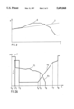
- FIG. 1 the speed-time diagram of the control process
- FIG. 1A the pressure-time diagram of the control process
- FIG. 2 the speed-time diagram of the regulation process
- FIG. 2A the pressure-time diagram of the regulation process
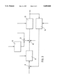
- FIG. 3 a block diagram of the automatic control system.
- the control process is explained with reference to FIGS. 1 and 1A.
- An upshift is shown.
- the gear-changing course of an engaging clutch 1 consists of: quick loading phase, load compensation phase, pressure build-up ramp according to a time function F2 and change to maximum pressure.
- the gear-changing course of a disengaging clutch 2 consists of: change from maximum to holding pressure, control phase with a time function F1, pressure reduction according to a time function F3 and complete disengagement.
- the switching starts at the moment t0 with the alter command.
- the clutch 1 In the time interval t1 to t3, the clutch 1 is loaded with high pressure, the quick loading pressure.
- the clutch 1 is preliminarily loaded by the quick loading pressure.
- the load compensation phase of the clutch 1 starts at the moment t3, after the quick loading phase. In the load compensation phase the clutch 1 is filled with the pressure medium.
- the load compensation phase terminates at t4. At the moment t4, one clutch-feeding element abuts on the friction elements of the clutch
- the pressure of the clutch 2 is lowered at the moment t2.
- the pressure course of the second clutch follows a first time function F1.
- the pressure in the clutch 2 is reduced until a slight speed difference, such as ⁇ 10 rpm, appears.
- the speed difference is calculated from the actual transmission input speed 6 minus the product 7 of the old reduction ratio multiplied by the transmission output speed.
- the amounts of pressure reduction in clutch 2 and of pressure build-up in clutch 1 are equal.
- the speed difference drops to almost zero, since the clutch 1 starts transmitting torque.
- the shifting course of the clutch 1 consists of: quick loading phase, load compensation phase, pressure build-up ramp according to a time function F2 and change to maximum pressure.
- the shifting course for the clutch 2 consists of: change from maximum to holding pressure, regulating phase with a time function F1, pressure reduction according to a time function F3 and complete disengagement.
- the shifting starts at the moment t0 with the alter command.
- the clutch 1 is charged with high pressure, the quick loading pressure, in the time interval t1 to t3.
- the clutch 1 is preliminarily loaded by the quick loading pressure.
- the load compensation phase of the clutch 1 starts at the moment t3, after the quick loading phase. In the load compensation phase the clutch 1 is loaded with the pressure medium.
- the load compensation phase terminates a t4. At the moment t4, a clutch-feeding element abuts on the friction elements of the clutch 1. Still no torque has been transmitted.
- the pressure in the clutch 2 is lowered at the moment t2.
- This new pressure value is slightly higher than the theoretic holding pressure. Due to the pressure drop, a slight speed difference appears in the clutch 2.
- the speed difference is calculated from the actual transmission input speed 6 minus the product 7 of the old reduction ratio multiplied by the transmission output speed.
- a first time function F1 begins for the clutch 2, the clutch pressure is lowered by the regulation until the speed difference corresponds to a desired value.
- the pressure ramp of the clutch 1 starts at the moment t4.
- the pressure build-up follows a second time function F2.
- the clutch 1 starts transmitting a torque as a result of the pressure level.
- the speed difference is thereby reduced at moment t5.
- the regulator unit follows a desired characteristic line for the speed difference and lowers the pressure in the clutch 2 in accordance with a third time function F3.
- the clutch 1 has fully taken up the load at the moment t6, so that the speed difference is almost zero, and the hydraulic pressure in the clutch 2 is lowered to zero.
- the second time function F2 of the clutch 1 is terminated at the moment t7, at t8 the maximum pressure abuts on the clutch 1.
- the shifting operation has ended.
- the third time function F3 of the clutch 2 be decisively determined by a special function.
- the special function is activated when the pressure build-up in the clutch 1 occurs too suddenly during the second time function F2, time interval t4 to t7. This is detected when the speed difference has dropped to about 50% of the desired value.
- the special function prevents the clutch 2 from closing again due to a too slow regulating behavior.
- the hydraulic pressure of the clutch 2 be additionally controlled depending on the load. This ensures that, in case of load changes during the shifting, the pressure of the clutch 2 can follow the load change under control and not be produced by great changes of the speed difference and thus of the output error.
- the slip phase starts at the t2 moment with the lowering of pressure and terminates with the complete disengagement of the clutch 2;
- the special function is activated when the clutch 1 starts transmitting a torque during the load compensation phase, t3 to t4. This can be caused by tolerances of structural parts.
- the pressure in the clutch 2 is reduced during the first time function F1 by the special function.
- the loading degree and the torque take-up in the clutch 1 are uncertain as a result of the viscosity of the pressure medium. Therefore, the regulation process is used at first. Upon reaching the operating temperature, the pressure build-up in the clutch 1 follows the controlled standard, and a change is made to the control process;
- the control process is used at first.
- a change is made to the regulation process.
- the process begins with the first time function F1 at the moment t2 of FIG. 2 and 2A.
- the introduction of an adaptive function is suggested as a compliment. This function is always activated upon a change from the control process to the regulation process due to an increase of the speed difference.
- the adaptive function effects a gradual lengthening of the quick loading time. The preliminary loading of the clutch 1 is thereby improved. The quick loading time is prolonged until the subsequent shifting in the loading of the clutch 1 follows the controlled standard.
- FIG. 3 shows a closed control loop consisting of a control unit 9, a first function block 12, the controlled system 13 and a second function block 14.
- a command variable and a control variable are compared at the addition point 8.
- the command variable is a desired standard of the speed difference.
- the control variable which is the output quantity of the second function block 14, is the actual speed difference in the clutch 2.
- An actuating signal results from a comparison of the command variable minus the control variable. Said actuating signal is an input quantity of the control unit 9. Depending on the actuating signal, the control unit 9 adjusts a pressure value, the regulated quantity.
- the following pressure portions are added: regulated quantity, pressure of a special function and the pressure portion from the third addition point 11.
- the special function effects an immediate and complete opening of the clutch 2 when the speed difference has dropped to zero or near zero.
- the third addend of the addition point 10 is the result of the third addition point 11 and adjusts the regulated quantity.
- the addition point 11 adds a load-dependent pressure portion with a pressure portion, which is the output quantity of the first function block 12.
- the first function block 12 has the task of adjusting a pressure value in accordance with the actual engine torque.
- the input quantities of the controlled system 13 are the result of the addition point 10 and another special function.
- the clutch 2 adjusts the controlled system 13. When the speed difference amounts to substantially 50% of the desired value standard, the special function acts directly upon the controlled system 13 and prevents the clutch 2 from closing again.
- the input quantities for the second function block 14 are the two output quantities of the controlled system, transmission input and output speeds, and the ratio of the speed level before the start of the switching operation.
- the actual speed difference is calculated in the second function block 14.
- the speed difference results from the actual transmission input speed 6 minus the product 7 of the old reduction ratio multiplied by output speed.
- the output quantity of the second function block 14 is the actual speed difference in the clutch 2 as a regulating variable.
- the regulating variable is compared at the addition point 8 with the command signal, and the control loop is closed.
- control loop The function of the control loop is explained with reference to the pressure-time diagram of FIG. 2A.
- the speed difference is zero.
- the addition point 8 results in a maximum actuating signal from the comparison of the command signal and the regulating variable.
- the pressure in the clutch 2 is lowered until a speed difference appears in the clutch 2. If the engine torque and the load are not changed during the shifting operation, the control unit acts upon the controlled system until no actuating signal exists any more, that is, the actual speed difference in the clutch 2 corresponds to a given speed-difference value. This is the time interval t2 to t5 in FIG. 2A. After termination of the loading phase of the clutch 1, the pressure build-up begins according to a second time function F2.
Landscapes
- Engineering & Computer Science (AREA)
- General Engineering & Computer Science (AREA)
- Physics & Mathematics (AREA)
- Fluid Mechanics (AREA)
- Mechanical Engineering (AREA)
- Control Of Transmission Device (AREA)
Applications Claiming Priority (3)
| Application Number | Priority Date | Filing Date | Title |
|---|---|---|---|
| DE4240621A DE4240621A1 (de) | 1992-12-03 | 1992-12-03 | Verfahren zur Steuerung und Regelung der Lastübernahme bei einem automatischen Schaltgetriebe |
| DE4240621.8 | 1992-12-03 | ||
| PCT/EP1993/003357 WO1994012814A1 (fr) | 1992-12-03 | 1993-12-01 | Procede pour la commande et la regulation de la reprise de charge dans une boite de vitesse automatique |
Publications (1)
| Publication Number | Publication Date |
|---|---|
| US5609068A true US5609068A (en) | 1997-03-11 |
Family
ID=6474264
Family Applications (1)
| Application Number | Title | Priority Date | Filing Date |
|---|---|---|---|
| US08/433,451 Expired - Fee Related US5609068A (en) | 1992-12-03 | 1993-12-01 | Process for controlling and regulating the load take-up in an automatic gearbox |
Country Status (6)
| Country | Link |
|---|---|
| US (1) | US5609068A (fr) |
| EP (1) | EP0670975B1 (fr) |
| JP (1) | JPH08503764A (fr) |
| DE (2) | DE4240621A1 (fr) |
| ES (1) | ES2106497T3 (fr) |
| WO (1) | WO1994012814A1 (fr) |
Cited By (15)
| Publication number | Priority date | Publication date | Assignee | Title |
|---|---|---|---|---|
| WO1998058196A1 (fr) * | 1997-06-17 | 1998-12-23 | Zf Friedrichshafen Ag | Procede pour reduire les a-coups lors du changement de rapports |
| US6157883A (en) * | 1996-11-22 | 2000-12-05 | Zf Friedrichshafen Ag | Increasing the spontaneity of an automatic gear box |
| US6173227B1 (en) * | 1996-01-12 | 2001-01-09 | Zf Friedrichshafen Ag | Method of setting the transmission ratio of a continuously variable gear |
| US6186923B1 (en) | 1997-05-31 | 2001-02-13 | Zf Friedrichshafen Ag | Increased automatic gear box spontaneity |
| US6216075B1 (en) * | 1996-08-01 | 2001-04-10 | Zf Friedrichshafen Ag | Process for determining the operating point of a continuously variable transmission |
| US6212966B1 (en) | 1998-12-23 | 2001-04-10 | Agco Limited | Control system for a power shuttle gearbox |
| US6261204B1 (en) * | 1997-10-06 | 2001-07-17 | Zf Friedrichshafen Ag | Method for adaptation of pressure of an overlapping upshifting |
| US20060040786A1 (en) * | 2002-09-27 | 2006-02-23 | Christian Popp | Method for increasing the spontaneity of an automatic transmission |
| US20060219509A1 (en) * | 2005-03-31 | 2006-10-05 | Caterpillar Inc. | System and method for controlling engagement of a clutch |
| US20080020897A1 (en) * | 2006-07-18 | 2008-01-24 | Jatco Ltd | Control apparatus and method for automatic transmission |
| US20080017467A1 (en) * | 2006-07-18 | 2008-01-24 | Jatco Ltd | Control apparatus and method for automatic transmission |
| US20080026910A1 (en) * | 2006-07-31 | 2008-01-31 | Jatco Ltd | Control apparatus and method for automatic transmission |
| WO2009085006A1 (fr) * | 2008-01-01 | 2009-07-09 | Husqvarna Ab | Commande de limitation de régime de moteur |
| FR2970054A1 (fr) * | 2011-01-03 | 2012-07-06 | Renault Sa | Procede de commande d’une boite de vitesse automatique |
| US9709159B2 (en) | 2015-06-11 | 2017-07-18 | Zf Friedrichshafen Ag | Method for controlling the transfer of torque of a force-fitting shift element |
Families Citing this family (19)
| Publication number | Priority date | Publication date | Assignee | Title |
|---|---|---|---|---|
| DE4424456A1 (de) * | 1994-07-12 | 1996-01-18 | Zahnradfabrik Friedrichshafen | Verfahren zum Steuern eines Automatgetriebes |
| DE4442991A1 (de) * | 1994-12-02 | 1996-06-05 | Zahnradfabrik Friedrichshafen | Automatisches Getriebe |
| JPH08240260A (ja) * | 1995-03-03 | 1996-09-17 | Toyota Motor Corp | 自動変速機の変速制御装置 |
| DE19511897C2 (de) * | 1995-03-31 | 1999-06-02 | Daimler Chrysler Ag | Verfahren zum Steuern einer ein- und ausrückbaren Reibschlußverbindung bei einer Schaltungsvorrichtung eines automatischen Stufengetriebes eines Kraftfahrzeuges |
| DE19526273C2 (de) * | 1995-07-19 | 1999-12-09 | Ford Werke Ag | Automatisch schaltbares Vorgelege-Wechselgetriebe, insbesondere für Kraftfahrzeuge |
| JP3471496B2 (ja) * | 1995-08-31 | 2003-12-02 | ジヤトコ株式会社 | 自動変速機の作動油圧制御装置 |
| JP3446426B2 (ja) * | 1995-11-09 | 2003-09-16 | トヨタ自動車株式会社 | 自動変速機の変速制御装置 |
| DE19544517C2 (de) * | 1995-11-29 | 1999-08-05 | Siemens Ag | Steuereinrichtung für ein automatisches Kraftfahrzeuggetriebe |
| JP3331844B2 (ja) * | 1995-12-19 | 2002-10-07 | アイシン・エィ・ダブリュ株式会社 | 自動変速機の油圧制御装置 |
| JP4012581B2 (ja) * | 1996-01-08 | 2007-11-21 | 本田技研工業株式会社 | 自動変速機の変速制御方法 |
| DE69738010T2 (de) * | 1996-09-25 | 2008-04-30 | Honda Giken Kogyo K.K. | Steuereinrichtung für hydraulisch betätigtes Fahrzeug |
| US6281195B1 (en) | 1997-02-07 | 2001-08-28 | Stryker Corporation | Matrix-free osteogenic devices, implants and methods of use thereof |
| US7041641B2 (en) | 1997-03-20 | 2006-05-09 | Stryker Corporation | Osteogenic devices and methods of use thereof for repair of endochondral bone and osteochondral defects |
| DE19714853A1 (de) | 1997-04-10 | 1998-10-15 | Zahnradfabrik Friedrichshafen | Erhöhung der Spontanität eines Automatgetriebes |
| DE19714852C1 (de) * | 1997-04-10 | 1998-08-13 | Zahnradfabrik Friedrichshafen | Verfahren zur Erhöhung der Spontanität eines elektrohydraulisch gesteuerten Automatikgetriebes |
| DE19928674B4 (de) * | 1999-06-23 | 2004-04-22 | Zf Friedrichshafen Ag | Steuerung einer Überschneidungsschaltung nach einem vorgegebenen Abtriebsmoment |
| DE102005001831A1 (de) * | 2005-01-14 | 2006-07-27 | Zf Friedrichshafen Ag | Verfahren zur Verbesserung der Schaltgeschwindigkeit von Automatgetrieben |
| DE102007035298A1 (de) * | 2007-07-27 | 2009-01-29 | Zf Friedrichshafen Ag | Verfahren zum Betreiben eines Automatgetriebes eines Fahrzeuges |
| JP5207080B2 (ja) * | 2009-10-30 | 2013-06-12 | アイシン・エィ・ダブリュ株式会社 | 車両用制御装置 |
Citations (9)
| Publication number | Priority date | Publication date | Assignee | Title |
|---|---|---|---|---|
| US4219109A (en) * | 1977-02-14 | 1980-08-26 | Toyota Jidosha Kogyo Kabushiki Kaisha | Oil pressure control means for an automatic transmission |
| EP0288779A2 (fr) * | 1987-04-30 | 1988-11-02 | Ford-Werke Aktiengesellschaft | Commande d'embrayage pour une transmission |
| US4942787A (en) * | 1988-03-03 | 1990-07-24 | Honda Giken Kogyo Kabushiki Kaisha | Apparatus for and method of controlling hydraulic clutch operation in an automatic transmission |
| US4984483A (en) * | 1987-04-15 | 1991-01-15 | Mitsubishi Jidosha Kogyo Kabushiki Kaisha | Control system for an automatic transmission of a motor vehicle |
| EP0435378A2 (fr) * | 1989-12-26 | 1991-07-03 | General Motors Corporation | Méthode pour commander des changement de vitesse dans une transmission automatique |
| DE4114382A1 (de) * | 1990-05-01 | 1991-11-21 | Nissan Motor | Kupplungsumschaltung bei einem automatischen getriebe |
| US5079970A (en) * | 1990-10-24 | 1992-01-14 | General Motors Corporation | Acceleration-based control of power-on downshifting in an automatic transmission |
| US5234087A (en) * | 1990-12-21 | 1993-08-10 | Mercedes-Benz Ag | Pressure medium actuated method and friction clutch with exclusively axially movable friction discs |
| US5285880A (en) * | 1991-05-23 | 1994-02-15 | Nissan Motor Co., Ltd. | Method and apparatus for controlling automatic transmission |
Family Cites Families (1)
| Publication number | Priority date | Publication date | Assignee | Title |
|---|---|---|---|---|
| EP0435376B1 (fr) * | 1989-12-26 | 1995-04-05 | General Motors Corporation | Méthode pour commander un changement de vitesse dans une transmission automatique |
-
1992
- 1992-12-03 DE DE4240621A patent/DE4240621A1/de not_active Withdrawn
-
1993
- 1993-12-01 US US08/433,451 patent/US5609068A/en not_active Expired - Fee Related
- 1993-12-01 WO PCT/EP1993/003357 patent/WO1994012814A1/fr active IP Right Grant
- 1993-12-01 DE DE59306896T patent/DE59306896D1/de not_active Expired - Fee Related
- 1993-12-01 ES ES94901922T patent/ES2106497T3/es not_active Expired - Lifetime
- 1993-12-01 EP EP94901922A patent/EP0670975B1/fr not_active Expired - Lifetime
- 1993-12-01 JP JP6512783A patent/JPH08503764A/ja active Pending
Patent Citations (9)
| Publication number | Priority date | Publication date | Assignee | Title |
|---|---|---|---|---|
| US4219109A (en) * | 1977-02-14 | 1980-08-26 | Toyota Jidosha Kogyo Kabushiki Kaisha | Oil pressure control means for an automatic transmission |
| US4984483A (en) * | 1987-04-15 | 1991-01-15 | Mitsubishi Jidosha Kogyo Kabushiki Kaisha | Control system for an automatic transmission of a motor vehicle |
| EP0288779A2 (fr) * | 1987-04-30 | 1988-11-02 | Ford-Werke Aktiengesellschaft | Commande d'embrayage pour une transmission |
| US4942787A (en) * | 1988-03-03 | 1990-07-24 | Honda Giken Kogyo Kabushiki Kaisha | Apparatus for and method of controlling hydraulic clutch operation in an automatic transmission |
| EP0435378A2 (fr) * | 1989-12-26 | 1991-07-03 | General Motors Corporation | Méthode pour commander des changement de vitesse dans une transmission automatique |
| DE4114382A1 (de) * | 1990-05-01 | 1991-11-21 | Nissan Motor | Kupplungsumschaltung bei einem automatischen getriebe |
| US5079970A (en) * | 1990-10-24 | 1992-01-14 | General Motors Corporation | Acceleration-based control of power-on downshifting in an automatic transmission |
| US5234087A (en) * | 1990-12-21 | 1993-08-10 | Mercedes-Benz Ag | Pressure medium actuated method and friction clutch with exclusively axially movable friction discs |
| US5285880A (en) * | 1991-05-23 | 1994-02-15 | Nissan Motor Co., Ltd. | Method and apparatus for controlling automatic transmission |
Cited By (20)
| Publication number | Priority date | Publication date | Assignee | Title |
|---|---|---|---|---|
| US6173227B1 (en) * | 1996-01-12 | 2001-01-09 | Zf Friedrichshafen Ag | Method of setting the transmission ratio of a continuously variable gear |
| US6216075B1 (en) * | 1996-08-01 | 2001-04-10 | Zf Friedrichshafen Ag | Process for determining the operating point of a continuously variable transmission |
| US6157883A (en) * | 1996-11-22 | 2000-12-05 | Zf Friedrichshafen Ag | Increasing the spontaneity of an automatic gear box |
| US6186923B1 (en) | 1997-05-31 | 2001-02-13 | Zf Friedrichshafen Ag | Increased automatic gear box spontaneity |
| WO1998058196A1 (fr) * | 1997-06-17 | 1998-12-23 | Zf Friedrichshafen Ag | Procede pour reduire les a-coups lors du changement de rapports |
| US6183393B1 (en) | 1997-06-17 | 2001-02-06 | Zf Friedrichshafen Ag | Method for reducing jerking during gear shifting |
| US6261204B1 (en) * | 1997-10-06 | 2001-07-17 | Zf Friedrichshafen Ag | Method for adaptation of pressure of an overlapping upshifting |
| US6212966B1 (en) | 1998-12-23 | 2001-04-10 | Agco Limited | Control system for a power shuttle gearbox |
| US7247127B2 (en) | 2002-09-27 | 2007-07-24 | Zf Friedrichshafen Ag | Method for increasing the spontaneity of an automatic transmission |
| US20060040786A1 (en) * | 2002-09-27 | 2006-02-23 | Christian Popp | Method for increasing the spontaneity of an automatic transmission |
| US20060219509A1 (en) * | 2005-03-31 | 2006-10-05 | Caterpillar Inc. | System and method for controlling engagement of a clutch |
| US20080020897A1 (en) * | 2006-07-18 | 2008-01-24 | Jatco Ltd | Control apparatus and method for automatic transmission |
| US20080017467A1 (en) * | 2006-07-18 | 2008-01-24 | Jatco Ltd | Control apparatus and method for automatic transmission |
| US7666113B2 (en) | 2006-07-18 | 2010-02-23 | Jatco Ltd | Control apparatus and method for automatic transmission |
| US7771316B2 (en) | 2006-07-18 | 2010-08-10 | Jatco Ltd | Control apparatus and method for automatic transmission |
| US20080026910A1 (en) * | 2006-07-31 | 2008-01-31 | Jatco Ltd | Control apparatus and method for automatic transmission |
| US7962267B2 (en) | 2006-07-31 | 2011-06-14 | Jatco Ltd | Control apparatus and method for automatic transmission |
| WO2009085006A1 (fr) * | 2008-01-01 | 2009-07-09 | Husqvarna Ab | Commande de limitation de régime de moteur |
| FR2970054A1 (fr) * | 2011-01-03 | 2012-07-06 | Renault Sa | Procede de commande d’une boite de vitesse automatique |
| US9709159B2 (en) | 2015-06-11 | 2017-07-18 | Zf Friedrichshafen Ag | Method for controlling the transfer of torque of a force-fitting shift element |
Also Published As
| Publication number | Publication date |
|---|---|
| EP0670975B1 (fr) | 1997-07-09 |
| WO1994012814A1 (fr) | 1994-06-09 |
| DE4240621A1 (de) | 1994-06-09 |
| DE59306896D1 (de) | 1997-08-14 |
| EP0670975A1 (fr) | 1995-09-13 |
| JPH08503764A (ja) | 1996-04-23 |
| ES2106497T3 (es) | 1997-11-01 |
Similar Documents
| Publication | Publication Date | Title |
|---|---|---|
| US5609068A (en) | Process for controlling and regulating the load take-up in an automatic gearbox | |
| US4527678A (en) | Transmission clutch control system and method | |
| US4370903A (en) | Method and apparatus for computing motor speeds for initiating and ending jolt control during gearshift in a drive system using fluid couplings or torque converters | |
| US5480363A (en) | Apparatus for controlling slip of lock-up clutch on motor vehicle during deceleration of the vehicle | |
| US5790967A (en) | Arrangement for controlling a frictional connection in a gear-changing appliance of an automatic discrete step gearbox of a motor vehicle | |
| US6128565A (en) | Hydraulic control system for automatic transmission | |
| US5020391A (en) | Apparatus for controlling gearshifts in automatic transmission using throttle and engine speed map schedule | |
| US6101438A (en) | Process for automatically co-ordinating the filling operation of shift elements | |
| US6259983B1 (en) | Hydraulic control system for automatic transmission | |
| US5207122A (en) | Clutch-to-clutch shifting in automatic transmission | |
| US5345843A (en) | Speed change control apparatus and method for an automotive automatic transmission | |
| JPS6188059A (ja) | 車両の自動変速機の電子制御方法 | |
| US6278926B1 (en) | Adaptive electronic transmission control system and strategy for nonsynchronous automatic transmission | |
| US6319172B1 (en) | Off-going clutch control for upshifting of an automatic transmission | |
| US20070167284A1 (en) | Method for operating a drive train of a vehicle | |
| CZ287122B6 (cs) | Ovládací zařízení automatické spojky | |
| US5368531A (en) | Control method of and system thereof for inversely proportionally raising and lowering servo hydraulic pressure, based on input torque, for engaging and disengaging frictional elements in automatic transmission | |
| EP0591244B1 (fr) | Systeme de commande d'embrayage | |
| US5283738A (en) | Process and device for controlling a clutch | |
| US6375597B1 (en) | Process for controlling an automatic gearbox | |
| US5105926A (en) | Slip control system for torque converter of automatic transmission | |
| US5128868A (en) | Apparatus for controlling gearshifts in automatic transmission | |
| US5499954A (en) | Control method and arrangement for a regulating variable determining a motor vehicle clutch rotational speed difference | |
| US5722913A (en) | Process for controlling an automatic gearbox | |
| US5752895A (en) | Automatic transmission lockup clutch control apparatus |
Legal Events
| Date | Code | Title | Description |
|---|---|---|---|
| AS | Assignment |
Owner name: ZF FRIEDRICHSHAFEN AG, GERMANY Free format text: ASSIGNMENT OF ASSIGNORS INTEREST;ASSIGNORS:GRUHLE, WOLF-DIETER;SIGG, PETER;DEISS, HARALD;AND OTHERS;REEL/FRAME:007509/0220;SIGNING DATES FROM 19950207 TO 19950214 |
|
| FEPP | Fee payment procedure |
Free format text: PAYOR NUMBER ASSIGNED (ORIGINAL EVENT CODE: ASPN); ENTITY STATUS OF PATENT OWNER: LARGE ENTITY |
|
| FPAY | Fee payment |
Year of fee payment: 4 |
|
| REMI | Maintenance fee reminder mailed | ||
| LAPS | Lapse for failure to pay maintenance fees | ||
| STCH | Information on status: patent discontinuation |
Free format text: PATENT EXPIRED DUE TO NONPAYMENT OF MAINTENANCE FEES UNDER 37 CFR 1.362 |
|
| FP | Lapsed due to failure to pay maintenance fee |
Effective date: 20050311 |