US5602452A - Regeneration current-spike limiter for six-step motor drives - Google Patents
Regeneration current-spike limiter for six-step motor drives Download PDFInfo
- Publication number
- US5602452A US5602452A US08/531,172 US53117295A US5602452A US 5602452 A US5602452 A US 5602452A US 53117295 A US53117295 A US 53117295A US 5602452 A US5602452 A US 5602452A
- Authority
- US
- United States
- Prior art keywords
- switches
- motor
- motor speed
- signal
- sensing
- Prior art date
- Legal status (The legal status is an assumption and is not a legal conclusion. Google has not performed a legal analysis and makes no representation as to the accuracy of the status listed.)
- Expired - Fee Related
Links
Images


Classifications
-
- H—ELECTRICITY
- H02—GENERATION; CONVERSION OR DISTRIBUTION OF ELECTRIC POWER
- H02P—CONTROL OR REGULATION OF ELECTRIC MOTORS, ELECTRIC GENERATORS OR DYNAMO-ELECTRIC CONVERTERS; CONTROLLING TRANSFORMERS, REACTORS OR CHOKE COILS
- H02P6/00—Arrangements for controlling synchronous motors or other dynamo-electric motors using electronic commutation dependent on the rotor position; Electronic commutators therefor
- H02P6/14—Electronic commutators
-
- H—ELECTRICITY
- H02—GENERATION; CONVERSION OR DISTRIBUTION OF ELECTRIC POWER
- H02P—CONTROL OR REGULATION OF ELECTRIC MOTORS, ELECTRIC GENERATORS OR DYNAMO-ELECTRIC CONVERTERS; CONTROLLING TRANSFORMERS, REACTORS OR CHOKE COILS
- H02P6/00—Arrangements for controlling synchronous motors or other dynamo-electric motors using electronic commutation dependent on the rotor position; Electronic commutators therefor
- H02P6/28—Arrangements for controlling current
-
- H—ELECTRICITY
- H02—GENERATION; CONVERSION OR DISTRIBUTION OF ELECTRIC POWER
- H02P—CONTROL OR REGULATION OF ELECTRIC MOTORS, ELECTRIC GENERATORS OR DYNAMO-ELECTRIC CONVERTERS; CONTROLLING TRANSFORMERS, REACTORS OR CHOKE COILS
- H02P6/00—Arrangements for controlling synchronous motors or other dynamo-electric motors using electronic commutation dependent on the rotor position; Electronic commutators therefor
- H02P6/34—Modelling or simulation for control purposes
Definitions
- the present invention relates generally to drives for DC brushless motors, and, more particularly, to an improved six-step motor drive therefor that is capable of limiting current spikes that may occur during an "aiding" or regenerative load and that might possibly damage solid-state switching components.
- Brushless DC motors typically have a permanent magnet rotor and three Y-connected field coils that are energized sequentially in series-connected pairs to form a rotating magnetic field to drive the rotor. Commutation of the coils is usually effected by three pairs of solid-state switches. These switches connect the terminals of each coil to either the power supply bus, or to ground, as appropriate. In the simplest control scheme (i.e., six step, trapezoidal control), these switches are operated as a function of the angular position of the rotor to sequentially connect the field coils, in various series-connected combinations, between the power source and ground. The currents supplied to the motor coils create the torque developed by the motor.
- motor currents are controlled by pulse-width-modulating the various switches, while feeding back the resulting voltage drop across a current-sensing resistor in a common return path to ground.
- the maximum value of motor current is usually determined by a limiting circuit, that opens the conducting switches when-ever the current-sensing voltage exceeds a preset amount.
- the present invention broadly provides an improved current-spike limiter (49) for use in a switching controller (21) for a DC brushless motor having Y-connected field coils (A, B, C), and having three electrically-controllable first switches (A U , B U , C U ), and three electrically-controllable second switches (A L , B L , C L ).
- Each first switch is connected between a positive supply voltage (22) and a terminal (26, 28, 29) of a respective one of the field coils (A, B, C), respectively.
- Each second switch is connected ground (23) and a terminal (26, 28, 29) of a respective one of the field coils.
- the switches are sequentially operated in a six-step mode to drive the motor.
- the improvement provides an improved current spike limiter (49), which broadly includes: means (50) for sensing regenerative operation of the motor, as in the case of "aiding" load; means (58) for sensing motor speed; and means (55) for momentarily opening a conducting one of the first switches for a predetermined time (t p ) after a predetermined delay (t d ) following a point in time (t s ) at which one of the second switches is closed and another of the second switches is opened.
- the duration of such momentary opening and the length of said predetermined delay are controlled as functions of sensed regenerative operation and said motor speed such that excessive current spikes in the conducting first switches will be eliminated.
- the means (50) for sensing regenerative operation of the motor includes a voltage comparator that senses the polarity of the motor velocity command signal relative to the motor current feedback signal.
- the means (58) for sensing the motor speed may simply be a tachometer arranged to generate a signal proportional to motor speed.
- the means for sensing motor speed may include a means for differentiating the output signal from an angular position sensor so as to produce a signal proportional to motor speed.
- the means (55, 56) for momentarily opening the conducting one of the first switches may include an adjustable electronic pulse generator capable of producing an output voltage pulse after a time delay following receipt of a trigger signal, the time duration of the pulse (t p ) and the time delay (t d ) each being a function of motor speed, and an AND gate operatively arranged to pass a trigger signal whenever the gate receives a first signal indicating regenerative operation of the motor, in combination with a second signal indicating that the motor speed has exceeded a predetermined threshold, the trigger being generated at a point in time when one of the second switches is opened and another of the second switches is closed.
- the present invention provides an improved drive circuit for the operation of six-step DC brushless motors.
- Another object is to provide an improved switching controller for a DC brushless motor, which controller includes means for preventing excessive and undesired current spikes that may possibly damage some of the solid-state components of the controller.
- FIG. 1 is a schematic view of a prior art switching controller in association with three Y-connected field coils of a DC brushless motor, this view showing all six switches as being opened.
- FIG. 2 is a schematic view illustrating the steps of sequential operation of various pairs of series-connected coils to provide a rotating magnetic field for driving the rotor.
- FIG. 3 is a view of the prior art controller shown in FIG. 1, but showing the current path when switches A U and B L , have been closed, this being just prior to the occurrence of a commutation point.
- FIG. 4 is a view of the prior art controller shown in FIG. 1, but showing the current path immediately after switch B L has been opened and switch C L has been closed.
- FIG. 5 is a block diagram showing the closed servoloop for operating the improved controller, this view also showing the current spike limiter.
- FIG. 6 is representative plot of motor current (ordinate) vs. time (abscissa), and comparatively illustrates two sequential waveforms, the first waveform showing the undesired current spike caused by the situation shown in FIG. 3, and the second waveform showing such spike as having been prevented due to the operation of the present invention.
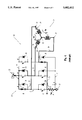
- FIG. 7 is a schematic view of the improved operation, showing switches B U and C L as having been closed, and showing the collapsing current in coils 26 and 25 as being modulated by switch C L .
- the terms “horizontal”, “vertical”, “left”, “right”, “up” and “down”, as well as adjectival and adverbial derivatives thereof simply refer to the orientation of the illustrated structure as the particular drawing figure faces the reader.
- the terms “inwardly” and “outwardly” generally refer to the orientation of a surface relative to its axis of elongation, or axis of rotation, as appropriate.
- a prior art DC brushless motor controller is shown as broadly including a switching circuit or controller, generally indicated at 21, operatively arranged between a positive voltage source 22 (labeled +V bus ), and a negative voltage source or ground 23.
- the switching circuit is shown in association with the Y-connected coils of a brushless DC motor, generally indicated at 24. These coils are severally indicated at A, B and C, respectively. Each coil is shown as having two terminals. The innermost terminals are connected at a common node 25. The outermost terminals of coils A, B and C are indicated at 26, 28 and 29, respectively.
- the DC brushless motor also includes a rotor that has been omitted from the drawings in the interest of clarity.
- the switching controller 21 is shown as having a total of six electrically-controllable switches, each embraced by a directional diode 30. For the sake of convenience, these switches are arranged in upper and lower banks of three horizontally-spaced switches each. The individual switches of each bank are labeled "A", "B” and “C”, respectively, with the subscripts "U” or “L” indicating whether a particular switch is in the upper or lower bank, respectively. In practice, each of these switches may be a transistor switch, or an equivalent solid-state device. Each switch has one terminal connected to a common bus 31 that is connected to the positive voltage source 22.
- switch A U is connected via line 32 with terminal 26 of coil A; the other terminal of switch B U is connected via conductor 33 with terminal 28 of coil B; and the other terminal of upper switch C U is connected by conductor 34 with terminal 29 of coil C.
- Lower switch A L has one terminal connected to conductor 32, and has another terminal connected to a common bus 35.
- Switch B L has one terminal connected to conductor 33, and has another terminal connected to common bus 35.
- Switch C L has one terminal connected to conductor 34, and has another terminal connected to common bus 35.
- Each of the lower-switch diodes 30 is connected between the terminal common to conductors 32, 33, 34, respectively, and to a common grounded conductor 36.
- a current-sensing resistor 38 is operatively arranged between conductors 35 and 36.
- step 1 current i AB flows through coils A and B; in step 2, current i AC flows through coils A and C; in step 3, current i BC flows through coils B and C; in step 4, current i BA flows through coils B and A; in step 5, current i CA flows through coils C and A; and, finally, in step 6, current i CB flows through coils C and B.
- the switching operation was typically effected as a function of the angular position of the rotor.
- a resolver or equivalent was used to determine the angular position of the rotor, and that angular position was then supplied to the controller to actuate the various switches in the necessary sequence to produce the six-step drive schematically indicated in FIG. 2.
- FIG. 3 illustrates the condition of the prior art controller shown in FIG. 1, just prior to commutation, with the darkened lines indicating the path of current flow.
- switches A U and B L have been closed, while the other switches remain opened.
- the motor is schematically shown has having batteries 39, 40 in series with coils A and B, respectively, as a result of the motor back EMF. This current is present as a result of the previous conduction, and the inductance of the coils.
- the critical difference is that, during "aiding" load operation, the polarity of the back EMF is reversed.
- FIG. 4 illustrates the condition of the prior art controller immediately after a commutation point. The difference here is that the back EMF voltage, which normally acts to reduce the current in coils A and B, instead contributes to this current's persistence after commutation.
- FIG. 4 illustrates the condition of the circuitry immediately after a commutation point (t s ) when switch A U remains closed, but switch B L has been opened and switch C L has been closed. In this situation, current may flow from source 22 through closed switch A U , conductor 32, coils A and C, closed switch C L , and conductor 35, through feedback resistor 38 to ground.
- the collapsing current i AB in coils A and B due to their past energization may flow through conductor 33, through the diode associate with switch B U to enter bus conductor 31.
- This current will add to the current flowing through switch A U , and may cause an undesired current spike that may possibly damage the solid-state switching components.
- FIG. 5 is a block diagram representing the various elements of the improved apparatus.
- the motor coils are shown as being connected via the six switches, again indicated at A U , B U , C U and A L , B L , C L , to switch controls 41, 42, 43 and 44, 45, 46, respectively.
- Each of these switch controls is in turn operated by a switching logic circuit, indicated at 48.
- the invention provides an improved current spike limiter, generally indicated within dashed lines 49.
- the current spike limiter includes a regeneration polarity comparator 50, which is provided with the sensed velocity signal and the velocity error signal output from summing point 53.
- a motor velocity command signal is supplied as a positive input to summing point 53.
- Summing point 53 algebraically sums the command and feedback signals, and provides an error signal to a pulse width modulator 54, that, in turn, provides its output signal to switching logic circuit 48.
- the velocity signal is also supplied to regeneration polarity comparator 50, and to box 58, labeled "speed thresh". Comparator 50 therefore compares the polarity of the velocity error and velocity feedback signals, and supplies its output to an AND gate 55.
- the "speed thresh” device compares the actual feedback velocity of the rotor with a minimum threshold velocity. Only if the actual velocity exceeds the threshold velocity will box 58 supply an output signal to AND gate 55.
- AND gate 55 receives another input signal from the switching logic circuit 48, representing the switch transfer pulse.
- AND gate 55 is arranged to provide its output signal to an adjustable pulse generator 56, that also receives a feedback velocity signal of the rotor.
- Pulse generator 56 is arranged to provide an appropriate signal to switching logic circuit 48, representing a command to momentarily open a switch in the upper bank for a predetermined time period (t p ) after a predetermined delay period (t d ) following the commencement (t s ) of a pulse, where t p and t d are functions of the motor speed ( ⁇ ).
- FIG. 6 is a plot of motor current vs. time, and illustrates schematically two sequential pulses, severally indicated at P 1 and P 2 , respectively.
- Pulse P 1 represents a pulse attributable to the prior art controller shown in FIG. 3.
- Pulse P 2 is representative of the operation of the new controller. Assuming conventional six-step trapezoidal control, pulse P 1 is shown as having a peak that exceeds the current limit due to the collapsing current in the previously-energized coils immediately following commutation.
- the present invention provides an improved current-spike eliminator that opens the conducting upper switch element at a point where the over current spike is about to begin, this being a predetermined time (t d ) after the lower element switch over (t s ), which is a function of motor speed ( ⁇ ), and holds it open for the predetermined time duration (t p ) of the spike.
- the improved circuitry functions to prevent the current from exceeding the current limit, by opening the upper switch for a time period t p that occurs a specified time duration, t d , following the beginning of the pulse t s . Since the current spike is prevented, and the current does not exceed its positive limit, the various solid-state components of the switching circuitry are protected.
- FIG. 7 The operation of the improved device is representatively shown in FIG. 7.
- switch A U is shown as having been opened during the time period t p .
- the collapsing current i AB in previously-energized coils A and B may flow through the diodes associated with switches B U and A L to the voltage source.
- the current flowing through coils A and C may flow through conductor 34, closed switch C L , resistor 38 to the ground.
- the magnitude of current i AC is modulated by selectively opening and closing lower switch C L .
- the present invention functions to sense regenerative operation of the motor, to sense the motor speed, and to momentarily open the conducting one of the upper switches for a predetermined time (t p ) after a predetermined delay (t d ) following the point in time (t s ) when one of the second switches is turned “off” and another of the second switches is turned “on”.
- the times t p and t d are controlled as functions of sensed regenerative operation and the rotor speed. Therefore, the improved invention functions to prevent the occurrence of current spike in six-step motor drives. By eliminating such spikes, the improved circuitry functions to protect the various solid-state components of the switching apparatus and motor controller.
Landscapes
- Engineering & Computer Science (AREA)
- Power Engineering (AREA)
- Control Of Motors That Do Not Use Commutators (AREA)
Priority Applications (4)
| Application Number | Priority Date | Filing Date | Title |
|---|---|---|---|
| US08/531,172 US5602452A (en) | 1995-09-19 | 1995-09-19 | Regeneration current-spike limiter for six-step motor drives |
| GB9618760A GB2305555A (en) | 1995-09-19 | 1996-09-09 | Regeneration current spike limiter for a brushless motor |
| JP8246643A JPH09168293A (ja) | 1995-09-19 | 1996-09-18 | 6ステップモータ駆動器用再生電流スパイクリミッタ |
| DE19638098A DE19638098A1 (de) | 1995-09-19 | 1996-09-18 | Rückkopplungs-Stromspitzenbegrenzer für sechsstufige Motorantriebe |
Applications Claiming Priority (1)
| Application Number | Priority Date | Filing Date | Title |
|---|---|---|---|
| US08/531,172 US5602452A (en) | 1995-09-19 | 1995-09-19 | Regeneration current-spike limiter for six-step motor drives |
Publications (1)
| Publication Number | Publication Date |
|---|---|
| US5602452A true US5602452A (en) | 1997-02-11 |
Family
ID=24116547
Family Applications (1)
| Application Number | Title | Priority Date | Filing Date |
|---|---|---|---|
| US08/531,172 Expired - Fee Related US5602452A (en) | 1995-09-19 | 1995-09-19 | Regeneration current-spike limiter for six-step motor drives |
Country Status (4)
| Country | Link |
|---|---|
| US (1) | US5602452A (de) |
| JP (1) | JPH09168293A (de) |
| DE (1) | DE19638098A1 (de) |
| GB (1) | GB2305555A (de) |
Cited By (8)
| Publication number | Priority date | Publication date | Assignee | Title |
|---|---|---|---|---|
| US5874817A (en) * | 1996-04-05 | 1999-02-23 | Mitsubishi Denki Kabushiki Kaisha | Motor driving circuit for a three-phase brushless motor |
| US5920176A (en) * | 1998-08-18 | 1999-07-06 | Dana Corporation | C-Dump topology noise reduction |
| US6066930A (en) * | 1996-09-03 | 2000-05-23 | Shindengen Electric Manufacturing Co., Ltd. | Synchronous driving method for inductive load and synchronous controller for H-bridge circuit |
| WO2000035074A1 (de) * | 1998-12-08 | 2000-06-15 | Papst-Motoren Gmbh & Co. Kg | Elektronisch kommutierter motor |
| US6304045B1 (en) | 1998-09-03 | 2001-10-16 | Siemens Automotive Inc. | Commutation of split-phase winding brushless DC motor |
| US6362585B1 (en) * | 2000-05-30 | 2002-03-26 | General Motors Corporation | Controlling electric vehicle DC bus voltage ripple under step mode of operation |
| US20060049785A1 (en) * | 2004-09-03 | 2006-03-09 | Guang-Nan Tzeng | Brushless motor drive device |
| US20190207539A1 (en) * | 2018-01-03 | 2019-07-04 | Milwaukee Electric Tool Corporation | Electronic braking in a power tool |
Citations (6)
| Publication number | Priority date | Publication date | Assignee | Title |
|---|---|---|---|---|
| US5119000A (en) * | 1991-02-25 | 1992-06-02 | Motorola, Inc. | Low noise motor drive circuit |
| US5220259A (en) * | 1991-10-03 | 1993-06-15 | Graco Inc. | Dc motor drive system and method |
| US5231338A (en) * | 1989-11-17 | 1993-07-27 | Sgs-Thomson Microelectronics S.R.L. | Controlling a multiphase brushless motor without position sensors for the rotor, using a system of digital filtering |
| US5291105A (en) * | 1991-10-15 | 1994-03-01 | Industrie Magneti Marelli | Control circuit for a half-wave brushless motor with a surge limiter |
| US5334921A (en) * | 1990-12-20 | 1994-08-02 | Robert Bosch Gmbh | Circuit arrangement for operating a multi-phase synchronous motor in a direct voltage network |
| US5428273A (en) * | 1993-01-14 | 1995-06-27 | U.S. Philips Corporation | Commutation circuit for a collectorless direct current motor |
Family Cites Families (3)
| Publication number | Priority date | Publication date | Assignee | Title |
|---|---|---|---|---|
| US4839754A (en) * | 1987-02-26 | 1989-06-13 | Micropolis Corporation | Winchester disk drive motor circuitry |
| DE4009184A1 (de) * | 1990-03-22 | 1991-09-26 | Heidelberger Druckmasch Ag | Verfahren zur unterdrueckung von stromspitzen waehrend einer kommutierung eines buerstenlosen gleichstrommotors |
| JP3290481B2 (ja) * | 1992-12-03 | 2002-06-10 | 東芝キヤリア株式会社 | 冷凍サイクル制御装置 |
-
1995
- 1995-09-19 US US08/531,172 patent/US5602452A/en not_active Expired - Fee Related
-
1996
- 1996-09-09 GB GB9618760A patent/GB2305555A/en not_active Withdrawn
- 1996-09-18 JP JP8246643A patent/JPH09168293A/ja active Pending
- 1996-09-18 DE DE19638098A patent/DE19638098A1/de not_active Ceased
Patent Citations (6)
| Publication number | Priority date | Publication date | Assignee | Title |
|---|---|---|---|---|
| US5231338A (en) * | 1989-11-17 | 1993-07-27 | Sgs-Thomson Microelectronics S.R.L. | Controlling a multiphase brushless motor without position sensors for the rotor, using a system of digital filtering |
| US5334921A (en) * | 1990-12-20 | 1994-08-02 | Robert Bosch Gmbh | Circuit arrangement for operating a multi-phase synchronous motor in a direct voltage network |
| US5119000A (en) * | 1991-02-25 | 1992-06-02 | Motorola, Inc. | Low noise motor drive circuit |
| US5220259A (en) * | 1991-10-03 | 1993-06-15 | Graco Inc. | Dc motor drive system and method |
| US5291105A (en) * | 1991-10-15 | 1994-03-01 | Industrie Magneti Marelli | Control circuit for a half-wave brushless motor with a surge limiter |
| US5428273A (en) * | 1993-01-14 | 1995-06-27 | U.S. Philips Corporation | Commutation circuit for a collectorless direct current motor |
Cited By (12)
| Publication number | Priority date | Publication date | Assignee | Title |
|---|---|---|---|---|
| US5874817A (en) * | 1996-04-05 | 1999-02-23 | Mitsubishi Denki Kabushiki Kaisha | Motor driving circuit for a three-phase brushless motor |
| US6066930A (en) * | 1996-09-03 | 2000-05-23 | Shindengen Electric Manufacturing Co., Ltd. | Synchronous driving method for inductive load and synchronous controller for H-bridge circuit |
| US5920176A (en) * | 1998-08-18 | 1999-07-06 | Dana Corporation | C-Dump topology noise reduction |
| US6304045B1 (en) | 1998-09-03 | 2001-10-16 | Siemens Automotive Inc. | Commutation of split-phase winding brushless DC motor |
| WO2000035074A1 (de) * | 1998-12-08 | 2000-06-15 | Papst-Motoren Gmbh & Co. Kg | Elektronisch kommutierter motor |
| US6362585B1 (en) * | 2000-05-30 | 2002-03-26 | General Motors Corporation | Controlling electric vehicle DC bus voltage ripple under step mode of operation |
| US20060049785A1 (en) * | 2004-09-03 | 2006-03-09 | Guang-Nan Tzeng | Brushless motor drive device |
| US7015663B1 (en) * | 2004-09-03 | 2006-03-21 | Aimtron Technology Corp. | Brushless motor drive device |
| US20190207539A1 (en) * | 2018-01-03 | 2019-07-04 | Milwaukee Electric Tool Corporation | Electronic braking in a power tool |
| US10720860B2 (en) * | 2018-01-03 | 2020-07-21 | Milwaukee Electric Tool Corporation | Electronic braking in a power tool |
| US11075594B2 (en) | 2018-01-03 | 2021-07-27 | Milwaukee Electric Tool Corporation | Electronic braking in a power tool |
| US11695352B2 (en) | 2018-01-03 | 2023-07-04 | Milwaukee Electric Tool Corporation | Electronic braking in a power tool |
Also Published As
| Publication number | Publication date |
|---|---|
| DE19638098A1 (de) | 1997-04-24 |
| GB9618760D0 (en) | 1996-10-23 |
| GB2305555A (en) | 1997-04-09 |
| JPH09168293A (ja) | 1997-06-24 |
Similar Documents
| Publication | Publication Date | Title |
|---|---|---|
| EP0506408B1 (de) | Steuerschaltung mit Energierückgewinnung für einen Reluktanzmotor | |
| US4988939A (en) | Electric motor with variable commutation delay | |
| US5825597A (en) | System and method for detection and control of circulating currents in a motor | |
| US5929577A (en) | Brushless DC motor controller | |
| US3947738A (en) | Pulsed power supply | |
| US5015927A (en) | Electric motor with regeneration current commutation | |
| US5675231A (en) | Systems and methods for protecting a single phase motor from circulating currents | |
| USRE36568E (en) | Current decay control in switched reluctance motor | |
| JP2599268B2 (ja) | モータ巻線の電流制御方法および装置 | |
| US6215261B1 (en) | Application specific integrated circuit for controlling power devices for commutating a motor based on the back emf of motor | |
| US5552685A (en) | Apparatus and method for detection and control of circulating currents in a variable speed DC motor | |
| US5483141A (en) | Method and apparatus for controlling refrigerator cycle | |
| US5896020A (en) | Driving circuit for a switched reluctance motor | |
| JP2791300B2 (ja) | 電気アシスト・モータの制御方法及び装置 | |
| US5079494A (en) | Fast response motor current regulator | |
| DE102008054487A1 (de) | Steuersystem für eine mehrphasige elektrische Drehmaschine | |
| US5602452A (en) | Regeneration current-spike limiter for six-step motor drives | |
| US5208518A (en) | DC-DC boost converter for spindle motor control | |
| JPS5986498A (ja) | パルス幅変調直流サ−ボモ−タ駆動回路 | |
| US10978973B2 (en) | Motor driving circuit and method thereof | |
| US5256949A (en) | AC power line current regeneration | |
| US6020695A (en) | Three-phase generator boost circuit | |
| CA1209199A (en) | Device for controlling a reluctance motor | |
| US5264770A (en) | Stepper motor driver circuit | |
| DE69831786T2 (de) | Kommutationsregler |
Legal Events
| Date | Code | Title | Description |
|---|---|---|---|
| AS | Assignment |
Owner name: MOOG INC., NEW YORK Free format text: ASSIGNMENT OF ASSIGNORS INTEREST;ASSIGNOR:UNDERHILL, MARK J.;REEL/FRAME:007669/0323 Effective date: 19950915 |
|
| AS | Assignment |
Owner name: MARINE MIDLAND BANK, AGENT, NEW YORK Free format text: SECURITY AGREEMENT;ASSIGNOR:MOOG INC.;REEL/FRAME:009748/0230 Effective date: 19981124 |
|
| REMI | Maintenance fee reminder mailed | ||
| LAPS | Lapse for failure to pay maintenance fees | ||
| FP | Expired due to failure to pay maintenance fee |
Effective date: 20010211 |
|
| STCH | Information on status: patent discontinuation |
Free format text: PATENT EXPIRED DUE TO NONPAYMENT OF MAINTENANCE FEES UNDER 37 CFR 1.362 |