US5507491A - Gaming terminal - Google Patents
Gaming terminal Download PDFInfo
- Publication number
- US5507491A US5507491A US08/124,623 US12462393A US5507491A US 5507491 A US5507491 A US 5507491A US 12462393 A US12462393 A US 12462393A US 5507491 A US5507491 A US 5507491A
- Authority
- US
- United States
- Prior art keywords
- terminal
- circuit
- information
- gaming
- data
- Prior art date
- Legal status (The legal status is an assumption and is not a legal conclusion. Google has not performed a legal analysis and makes no representation as to the accuracy of the status listed.)
- Expired - Fee Related
Links
Images


Classifications
-
- G—PHYSICS
- G06—COMPUTING; CALCULATING OR COUNTING
- G06F—ELECTRIC DIGITAL DATA PROCESSING
- G06F15/00—Digital computers in general; Data processing equipment in general
- G06F15/02—Digital computers in general; Data processing equipment in general manually operated with input through keyboard and computation using a built-in program, e.g. pocket calculators
-
- G—PHYSICS
- G07—CHECKING-DEVICES
- G07F—COIN-FREED OR LIKE APPARATUS
- G07F17/00—Coin-freed apparatus for hiring articles; Coin-freed facilities or services
- G07F17/32—Coin-freed apparatus for hiring articles; Coin-freed facilities or services for games, toys, sports, or amusements
-
- A—HUMAN NECESSITIES
- A63—SPORTS; GAMES; AMUSEMENTS
- A63F—CARD, BOARD, OR ROULETTE GAMES; INDOOR GAMES USING SMALL MOVING PLAYING BODIES; VIDEO GAMES; GAMES NOT OTHERWISE PROVIDED FOR
- A63F3/00—Board games; Raffle games
- A63F3/06—Lottos or bingo games; Systems, apparatus or devices for checking such games
- A63F3/0645—Electric lottos or bingo games
-
- A—HUMAN NECESSITIES
- A63—SPORTS; GAMES; AMUSEMENTS
- A63F—CARD, BOARD, OR ROULETTE GAMES; INDOOR GAMES USING SMALL MOVING PLAYING BODIES; VIDEO GAMES; GAMES NOT OTHERWISE PROVIDED FOR
- A63F3/00—Board games; Raffle games
- A63F3/08—Raffle games that can be played by a fairly large number of people
- A63F3/081—Raffle games that can be played by a fairly large number of people electric
- A63F2003/082—Raffle games that can be played by a fairly large number of people electric with remote participants
- A63F2003/086—Raffle games that can be played by a fairly large number of people electric with remote participants played via telephone, e.g. using a modem
-
- A—HUMAN NECESSITIES
- A63—SPORTS; GAMES; AMUSEMENTS
- A63F—CARD, BOARD, OR ROULETTE GAMES; INDOOR GAMES USING SMALL MOVING PLAYING BODIES; VIDEO GAMES; GAMES NOT OTHERWISE PROVIDED FOR
- A63F9/00—Games not otherwise provided for
- A63F9/24—Electric games; Games using electronic circuits not otherwise provided for
- A63F2009/2401—Detail of input, input devices
- A63F2009/2411—Input form cards, tapes, discs
- A63F2009/2413—Magnetic
- A63F2009/2414—Cards
-
- A—HUMAN NECESSITIES
- A63—SPORTS; GAMES; AMUSEMENTS
- A63F—CARD, BOARD, OR ROULETTE GAMES; INDOOR GAMES USING SMALL MOVING PLAYING BODIES; VIDEO GAMES; GAMES NOT OTHERWISE PROVIDED FOR
- A63F9/00—Games not otherwise provided for
- A63F9/24—Electric games; Games using electronic circuits not otherwise provided for
- A63F2009/2401—Detail of input, input devices
- A63F2009/2411—Input form cards, tapes, discs
- A63F2009/2419—Optical
- A63F2009/242—Bar codes
-
- A—HUMAN NECESSITIES
- A63—SPORTS; GAMES; AMUSEMENTS
- A63F—CARD, BOARD, OR ROULETTE GAMES; INDOOR GAMES USING SMALL MOVING PLAYING BODIES; VIDEO GAMES; GAMES NOT OTHERWISE PROVIDED FOR
- A63F9/00—Games not otherwise provided for
- A63F9/24—Electric games; Games using electronic circuits not otherwise provided for
- A63F2009/2401—Detail of input, input devices
- A63F2009/2411—Input form cards, tapes, discs
- A63F2009/2429—IC card, chip card, smart card
Definitions
- the present invention relates to terminals for games organized on a national scale, such as lottery games, lotto totalizers or the like.
- Such terminals generally form part of systems for placing bets.
- a system for placing bets generally includes terminals for placing bets located in gaming offices visited by the players who deposit at these offices gaming coupons which they have completed, together with the handing-over of a sum of money corresponding to the stake which they wager.
- the bet-placing terminals are either linked by a communication network to a central processing system or server centre and are so-called “on line” terminals, or autonomous so-called “off line” terminals.
- the gaming terminals are ordinarily equipped with devices for analyzing gaming coupons and often with separate devices for analysing receipts for determining, after the draw, the bearers of receipts who should receive winnings, together with the amounts of these winnings.
- the processing of a gaming coupon is carried out by inserting this coupon into a coupon analysis device of a terminal.
- This coupon is analysed in pixels and the image obtained is processed digitally.
- the aforesaid processing determines the type of coupon, the type of marks or signs written on the coupon by the players, and prepares a coded frame which is transmitted to the central processing system which records the corresponding transaction in a memory.
- a validation code is sent to the terminal which prints a receipt which marks the commitment of the gaming body towards the player of payment in the event of a win.
- the terminal furthermore includes means for analyzing the receipt after the draw in order to determine whether the bearer of the receipt has won or not.
- the coded numeral which it bears is transmitted by the terminal to the central system which interrogates the file of winners.
- the invention aims to enhance the existing gaming terminals by creating a gaming terminal which provides for the greatest number of functions mentioned above while still offering the most compact, modular construction possible and the simplest and safest possible manner of use.
- the subject of the invention is therefore a gaming terminal comprising means for analyzing information carriers, especially gaming coupons and receipts, means for processing the information resulting from the analysis of the information carriers, for converting these data into digital data and for transmitting these data to a remote or local processing system by way of a communication network, means for receiving data for validating gaming coupons and/or receipts originating from the remote or local processing system, data display means, a keyboard assembly associated with electronic means for controlling the various functions of the terminal characterized in that the means for analyzing the gaming coupons and receipts consist of a common information carrier analysis device comprising means for analyzing the signs written by the players on the coupons and means for reading bar codes representing the validation numerals of the receipts and in that these processing means include large-capacity, dividable storage means having zero retention energy consumption, on the one hand for the instructions for operating the terminal which are transmitted to them from the processing system, and on the other hand for the gaming data received by the terminal and in that it furthermore includes integrated-circuit passkey means for permitting or prohibiting access to the terminal.
- the storage means consist of at least one so-called “flash” segmented EEPROM memory.
- the terminal furthermore includes a device for reading magnetic codes and optical codes, which is associated with the device for analyzing information carriers.
- the terminal furthermore includes an integrated-circuit card reader associated with the information carrier analysis device.
- FIG. 1 is a general perspective view of a gaming terminal according to the invention
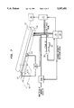
- FIG. 2 is a schematic diagram of the gaming terminal of FIG. 1;
- FIG. 3 is a detailed schematic diagram of the keyboard assembly of the gaming terminal according to the invention.
- FIGS. 4 and 5 are more detailed diagrams of the display devices of the terminal.
- FIG. 6 is a schematic diagram of the device controlling the supply to the gaming terminal
- FIG. 7 is a perspective diagrammatic view of the analysis device forming part of the terminal.
- FIG. 8 is a diagrammatic view in transverse section of the device of FIG. 7;
- FIG. 9 shows a gaming coupon intended to be processed by the device
- FIG. 10 shows the data of the gaming coupon of FIG. 9 which are picked out by the reading device
- FIG. 11 shows a receipt issued by the terminal and analyzed by the device
- FIG. 12 is a view of the bar code of the receipt of FIG. 11 on a larger scale, showing the manner of analysized said code;
- FIG. 13 is a flowchart illustrating the operation of the analysis device for a gaming coupon
- FIG. 14 is a flowchart illustrating the operation of the analyzisng device for a receipt
- FIG. 15 is an exploded perspective view of the device for analyzing information carriers
- FIG. 16 is an exploded perspective view of a detail of the device of FIG. 15;
- FIG. 17 is a view in transverse section of the housing of the analisis device, some of the parts of which have been removed;
- FIG. 18 is a view in transverse section of the assembled device
- FIG. 19 is a sectional view on a larger scale of a variant of the flap for guiding and receiving documents
- FIG. 20 is a sectional diagrammatic view of a first embodiment of a magneto-optical reader forming part of the terminal according to the invention.
- FIG. 21 is a sectional view similar to that of FIG. 20 representing a variant of the magneto-optical reader
- FIG. 22 is a flowchart of a way of determining the kind of signals delivered by the magneto-optical reader
- FIG. 1 Represented in perspective in FIG. 1 is a general outside view of the gaming terminal according to the invention.
- This terminal designated by the general reference 1, includes a rear housing 2 in which are placed most of the electronic circuits of the terminal and a front housing 3 essentially containing the means for actuation and for display for the terminal.
- the housing 2 contains an essential element of the terminal of the invention, namely a device 4 for analyzing data carriers.
- the housing For access to the analysis device 4, the housing includes a slot 5 delimited by lips 6 made from the same material as the housing 2.
- the housing 2 contains a printer 7 equipped with a cutter device, such as a thermal printer, above which is made a slot 8 provided in the housing 2 to enable printed documents to exit.
- a cutter device such as a thermal printer
- the housing 3 situated in front of the housing 2 includes a control keyboard 9 which will be described in further detail later on, a display screen 10 of the liquid-crystal type intended to display the information corresponding to the current running of commands for operating the terminal, a magneto-optical reader 11 intended for reading carriers bearing magnetic codes, and carrier bearing optical codes, a housing 12 with integrated-circuit passkey intended for monitoring access to the terminal in a way which will be described later and a reader 13 of integrated-circuit cards, especially monetary credit cards or gambling credit cards.
- FIG. 2 Represented in FIG. 2 is a schematic diagram of the gaming terminal according to the invention.
- the terminal 1 represented diagrammatically in FIG. 2 includes, firstly, an off-the-shelf microprocessor card 20, such as a 386 SX card from Intel Corporation, 3065 Bower Avenue, Santa Clara, Calif. 95052.
- an off-the-shelf microprocessor card 20 such as a 386 SX card from Intel Corporation, 3065 Bower Avenue, Santa Clara, Calif. 95052.
- This card 20 includes two serial input output circuits 21, 22, a parallel input output circuit 22a, a circuit 23 for connecting to a color graphics screen, a circuit 24 connected up to a switch 25 for selecting the operating speed of the terminal, a circuit 26 for linking to the keyboard 9, a loudspeaker output circuit 27 and a logic circuit for resetting 28. It furthermore includes circuits 29, 30 and 31 which can be used for connecting a hard disk, a diskette and an external microcomputer card.
- the ports for linking all these circuits to the aforesaid peripheral devices are manifested in the figure with a square barred with a cross.
- microprocessor 20 there is furthermore associated an ISA microcomputer bus 32 intended for linking the microprocessor 20 to a number of circuits and especially to a circuit or auxiliary card 33 containing an autonomous processing unit, a memory and a logic monitoring unit.
- ISA microcomputer bus 32 intended for linking the microprocessor 20 to a number of circuits and especially to a circuit or auxiliary card 33 containing an autonomous processing unit, a memory and a logic monitoring unit.
- the microprocessor 20 is furthermore linked by the bus 32 to a modem 34 for linking to a communication network to which the terminal is connected, with a "flash" type EEPROM memory card 35.
- This integrated memory circuit is manufactured and sold by the Intel Corporation company. It is intended for storing, on the one hand, the terminal operating programs loaded therein from the central processing system to which it is linked by the network and, on the other hand, the gaming data received by the terminal proper.
- This "flash" memory card 35 is associated with a “flash” memory card 36 which can be plugged in by means of a connector 37 and is intended to contain for example the gaming data gathered by the terminal over a given period.
- This memory card 36 can be withdrawn from the terminal so as to be transported to a processing centre.
- the "flash" type memories have the essential characteristics of being extremely difficult to access, if the appropriate means are not available, so that the transporting in such a memory of data relating to games which are to remain secret prior to the draw is much safer than the transporting of data for example in a memory of the diskette type which may be read extremely easily with the aid of an ordinary microcomputer.
- the microprocessor 20 is furthermore connected up by the bus 32 to a circuit 38 for connecting to a local network having a coaxial cable connection 39 and a twisted pair connection 40.
- the microprocessor 20 is moreover connected by the bus 32 to an interface circuit 41 intended for linking together mass storage units.
- This is a parallel local bus, of multi-media type, for example SCSI.
- the interface circuit 41 enables a multi-media CD-ROM reader to be linked to the terminal.
- the auxiliary card 33 is linked to two serial input/output circuits 42, 43, to a circuit 44 for monitoring the opening or closing of a cash till, to a circuit 45 for monitoring the electrical supply to the terminal, this circuit 45 being described in further detail with reference to FIG. 6, to the data analysis device 4 represented in FIG. 1, to an input/output circuit 46 associated with the keyboard 9 and to a circuit for controlling the thermal printer 7.
- the electrical current supply to the terminal is provided for either at 110 volts, or at 220 volts AC from 40 to 80 Hz and delivers DC voltages of various values, -5 volts, +5 volts, -12 volts, +12 volts and +24 volts for example.
- FIG. 3 Represented in further detail in FIG. 3 is the assembly of the keyboard 9 controlled by the keyboard input/output circuit 36 of FIG. 2.
- This keyboard assembly includes a matrix of keys associated with a monitoring circuit 51.
- the keyboard assembly furthermore includes a circuit 57 for controlling an optical or magnetic reader 58 commonly termed a "douchette" and linked by a flexible cable to the keyboard assembly.
- It also includes a circuit 59 for monitoring the magneto-optical reader 11 (FIG. 1) together with a circuit 60 for controlling, on the one hand, the liquid-crystal display screen of the terminal intended for the retailer and a liquid-crystal display device 61 intended for the players and linked to the terminal by a flexible cable, placed in such a way that the gamblers may see the result of their bet when their receipt is verified in the terminal following the draw of the game in which they participated.
- the liquid-crystal display device 10 intended for the retailer and represented in FIG. 5 includes a liquid-crystal display region 62 and a serial-parallel interface circuit 63.
- the liquid-crystal display device intended for the players includes a liquid-crystal display region 65 and a serial-parallel interface circuit 66, the two display devices 10 and 61 being linked to the control circuit 60 by way of respective interface circuits 63 and 66.
- FIG. 6 wherein is represented the circuit 45 for monitoring the supply to the terminal according to the invention.
- the supply circuit 70 which is itself supplied from the 220 volts network by way of a switch 71 and which is intended to deliver at its output a number of DC voltages ranging from -5 volts to +12 volts for example, these various supply voltages being applied to the central processing unit of the microprocessor 20, to the memory assembly and in particular to the "flash" memory 35, to the auxiliary card 33 as well as to other circuits of the terminal.
- the central unit of the microprocessor 20 is connected to the integrated-circuit passkey reading circuit 12 of a microchip passkey 73 which, as its name indicates, bears an integrated circuit 74 which contains the code for access to the terminal
- the output of the circuit 12 for reading the passkey 73 is furthermore connected to an input of an OR circuit 75, while the other input of the OR circuit is connected to a corresponding output of the central unit of the microprocessor 20.
- the output from the circuit 75 is intended to control the switch 71 for transmitting the voltage from the network to the supply circuit 70.
- the insertion of the passkey 73 into the reader 12 firstly causes the appearance of an output signal applied, on the one hand, to the central unit 20 and, on the other hand, to the corresponding input of the OR circuit 75. If the output signal from the reader 12 corresponds to the exact code for access to the terminal, the central unit 20 recognizes this code and transmits on its output connected to the OR circuit 75 a signal causing the appearance at the output of the circuit 75 of a signal for controlling the closing of the switch 71 and consequently for turning on the supply 70.
- the central unit 20 transmits on its output connected to the corresponding input of the circuit 75, a signal providing for the turning-off of this circuit and consequently the opening of the switch 71 and the cutting of the network voltage applied to the supply 70.
- the circuit of the terminal includes a microprocessor card 20 comprising its own conventional memories with which is associated the flash memory 35 and the auxiliary card 33 also utilizes a memory.
- the storage means associated with the central processing unit comprise a DRAM, the "flash" memory 35 intended to contain the coded and compressed software for the applications of the terminal, an SRAM and a ROM which are intended to contain fixed parameters such as internal tests, and basic transfer software.
- the memory 35 is therefore made in the form of a large-capacity segmented EEPROM having zero retention consumption and with which are associated specific access means 35a (FIG. 2) enabling the memory to be placed in communication with the remainder of the terminal, with other terminals of the network or with units for loading/downloading and for reading/writing the flash memory.
- part of the DRAM is configured in virtual disk form, the remainder being configured as a work memory.
- the files stored in the flash memory 35, in the SRAM and in the ROM are expanded, decoded and transferred either to the DRAM disk, or into the DRAM memory of the unit of the microprocessor 20.
- Access to the flash memory is conditional upon the recognizing by the access means 35a of the access code contained in the integrated circuit 74 of the microchip passkey 73.
- the application to be carried out is then executed.
- the flash memory 35 is updated with the information contained in the SRAM.
- the segmented structure of the flash memory 35 enables these operations to be executed in a minimum of time.
- the terminal reads the ROM disk and basic transfer software contained in the ROM calls up the server center or is called by the latter which remotely loads into the flash memory 35 the applications to be executed by the terminal.
- the flash card 36 connected to the flash memory 35 by the connector 37 as represented diagrammatically in FIG. 2 also forms part of the operating diagram just described.
- This facility is very advantageous for terminals which do not operate in an interconnected network but whose gaming data would be read out specifically with the aid of a removable memory and transported to a processing center with a view to being processed there.
- the data carrier analysis device 6 is advantageously of the type described in the French Patent Applications Nos. 92 10 642 of 7 Sep. 1992 and 92 11 112 of 17 Sep. 1992, which have been filed by the Applicant.
- This is a device comprising means for inserting an information carrier, means for reading the information on the carrier, means for processing the information read on the carrier with a view to its conversion into digital data and its transmission to a central gaming management unit.
- the means for reading the information on the carrier when the latter is a gaming coupon, comprise an optical reader which is blind to at least one color in which fixed information is printed on the carrier and which reader is sensitive to other colors, so as to take into account only the variable gaming information and the fixed information for aligning the carrier and for designating the type of game to which it belongs, which information is printed in these other colors.
- the analysis device represented schematically in FIG. 7 includes principally an image detector 101 arranged opposite a roller 102 for driving a document 103 to be analysed.
- the roller 102 is linked to an electric stepper motor 104 intended to allow analysis of the document 103 through successive scanning lines with a vertical resolution which depends on the step selected for the displacement of the roller 102.
- a data processing device 105 Connected up to the image detector 101 is a data processing device 105 which includes a memory 106 for temporary storage of the digital image data, prior to its transmission to a central gaming management unit (not represented).
- the device of FIG. 7 furthermore includes a logic circuit 107 for controlling the electric stepper motor 104 and a comparator 108 connected up between the data output of the image detector 101 and the input of the processing unit and intended to compare the output signal from the detector with a reference signal delivered by a signal source 109, as well as a circuit 109a for monitoring the luminous intensity which receives a luminous intensity monitoring signal originating from the processing unit 105.
- a logic circuit 107 for controlling the electric stepper motor 104 and a comparator 108 connected up between the data output of the image detector 101 and the input of the processing unit and intended to compare the output signal from the detector with a reference signal delivered by a signal source 109, as well as a circuit 109a for monitoring the luminous intensity which receives a luminous intensity monitoring signal originating from the processing unit 105.
- the processing unit 105 will be able, by comparison, to determine a correct intensity of the light source, appropriate to the processing in progress.
- the image detector 101 includes a row of light-emitting diodes 110, the number of which depends on the horizontal resolution and luminous intensity which are required.
- these diodes 110 there are associated members 111 for focusing and filtering the light, and intended to focus these beams 112 onto a transparent wall 113 of the housing of the detector, against which wall must be applied the face of the document to be analysed which bears, on the one hand, fixed inscriptions such as a gaming grid, grid box numerals, date and other indications, printed in the color of the light emitted and which will therefore not be reproduced by the device and, on the other hand, variable inscriptions made by the player in the gaming grid in a color which differs from that of the emitted light, as well as fixed inscriptions such as alignment tags, a code relating to the type of game to which the coupon belongs, printed in a color which differs from that of the emitted light, and which will be reproduced.
- fixed inscriptions such as a gaming grid, grid box numerals, date and other indications
- the plane of symmetry of the roller 102 and the optical axis of the light conductors 114 have a slight offset in the direction of insertion of a document in order to allow the front edge of this document to reflect the light emitted by the monochromatic light source, thereby conveying the presence of the document at this location.
- the members 111 for focusing and filtering the beams emitted by the light-emitting diodes 110 are made in the form of thick plano-concave lenses whose concave face has a curvature such that the beam exiting a lens overlaps the beam exiting a neighboring lens.
- the light emitted by the set of light-emitting diodes has the appearance of a continuous monochromatic luminous stroke of red color for example.
- the device furthermore includes detectors 117, 118 arranged opposite the slot between the roller 102 and the image detector 101, at an axial distance from one another which is slightly greater than the transverse dimension a of the smallest document to be read.
- the outputs of the detectors 117, 118 are connected up to the processing unit 105 through a circuit 119.
- Such a layout makes it possible to distinguish between a document of small width, such as a receipt which prompts the actuation of a single detector, and a document of greater width, such as a gaming coupon which triggers two detectors, and to prompt within the processing unit 105 the intervention of a program appropriate to the processing of the corresponding document.
- a lotto gaming coupon which includes a gaming grid 120 containing numerals printed in the color of emission of the light sources of the detector, that is to say in red in the present example.
- This coupon furthermore bears, printed in red, an upper zone 121 indicating the day and period of validity of the coupon and to the left of this zone, the word "LOTTO" is printed on a blue background in respect of the letters L and T and on a red background in respect of the letters O.
- the ticket moreover includes a lower zone 122 with red background on which appears in white the inscription "6 out of 49" indicating the number of numerals to be ticked.
- the other zones of the coupon are printed in colors which allow them to be detected by the reading device.
- regions 123, 124 for aligning the coupon are regions 123, 124 for aligning the coupon, a region 125 for identifying the type of game to which the coupon belongs and inscriptions 126 indicating for example the number of draws and the corresponding prize to be paid out.
- FIG. 10 Represented in FIG. 10 is the image of the coupon of FIG. 9 which results from the analysis by the device according to the invention and which appears on the display means associated with the latter.
- the image of the coupon of FIG. 10 will be completed by superimposing on the information of FIG. 10 from the image, a reconstructed game analysis marking pattern such as a grid identical to the grid 120 of the coupon of FIG. 9
- FIG. 11 Represented in FIG. 11 is the image of a gaming receipt delivered to the player by the gaming terminal and the reading of which is also ensured by the analysis device according to the invention.
- the receipt also includes a number of regions intended to be analyzed and in particular a region 130 containing a bar code for validating the coupon presented by a player.
- This code which is sometimes printed with printing defects, must be recognized by the device according to the invention with maximum accuracy.
- It consists of a first part 131 formed of bars arranged at regular intervals and which embody clock signals and of a second part 132 formed of bars defining data signals corresponding to the validation code proper.
- a horizontal histogram 133a intended for calculating the angle of inclination ⁇ of the receipt.
- the positions of the sectors 134 and 135 are chosen on each side of the line of separation of the clock signals and data signals.
- This sweeping takes account of the printing defects, since it is accepted by convention that the detecting of for example 60% of the points out of the totality of points forming a bar confirms the presence of a bar and causes it to be taken into account in respect of the analysis of the code.
- the counting of the data signals is carried out by performing a logical AND operation between a clock bar and a data bar which may possibly lie opposite this clock bar.
- the sweeping operation is triggered by the presenting of a document to the analysis device by insertion between the roller 102 and the image detector 101.
- the plane of symmetry of the roller 102 perpendicular to the transparent face 113 of the detector is offset with respect to the optical axis of the set of light conductors 114 so that the edge of a document engaged between the roller 102 and the light detector 101 may lie beyond this optical axis and so that the document may reflect the light originating from the light-emitting diodes 110 as soon as it is put in place.
- the parallelism between the edge of the document and the lines of light-emitting diodes is checked by making provision for a minimum number of photosensitive elements 116 to have to receive the light reflected by the edge of the document in order to accept that its position with respect to the line of diodes is correct, that is to say that its defect in parallelism with respect to the line of diodes is tolerable.
- This parallelism can also be checked by determining a minimum distance between two illuminated photosensitive elements.
- the processing device actuates the stepper motor for driving the roller 102 and line-by-line reading of the document can be performed.
- the minimum distance between two elements or the minimum number of illuminated light-emitting elements differs depending on the transverse dimension of the document to be analysed.
- phase 140 The placing of a document on the analysis device is performed in phase 140.
- Whether the document is a coupon or a receipt is determined by means of the detectors 117, 118 during phases 141 and 142.
- the document is a gaming coupon
- the edges of the coupon which are embodied through eight tags 123 represented in FIGS. 9 and 10 are searched for with a view to the approximate aligning of the coupon.
- This search is effected in phase 144. If the coupon does not include any marks for accurate alignment, it is established during phase 145 that the coupon examined is a coupon of the old type which requires, during a procedure embodied overall by a phase 146, a specific search corresponding to each coupon.
- the coupon includes marks 124, it is established during phase 147 that this is a coupon which can be processed by the device.
- phase 148 the inclination of the coupon with respect to the generatrix of the roller 102 is established and the processing system compensates for this inclination.
- the coupon is searched for the code relating to the type of game to which it belongs and which is represented at 125 in FIGS. 9 and 10.
- phase 150 there is undertaken the sending of the code relating to the type of game to a device with memory for storing the various information items relating to the gaming grids, which during phase 151 sends back a table of regions.
- phase 152 there is undertaken the search for the crosses in the regions of the ticket where they have been placed.
- phase 153 the information relating to the table and to the crosses placed by the player on the ticket and embodied by their coordinates is returned to the central unit.
- the recording of the data relating to a coupon is then complete.
- phase 156 the inclination of the receipt is calculated and, during phase 157, the region 130 containing the bar code which is represented in FIG. 11 is searched for.
- phase 158 the compensating of the inclination calculated during phase 156 is undertaken.
- phase 159 a horizontal histogram is compiled of a region of about 20% of the region 130 containing the bar code followed by a filtering and digital smoothing which are performed during phase 160.
- phase 161 a search is made for the downward verge in the largest area of the graph of the histogram 133 (FIG. 11).
- phase 162 the largest downward verge corresponding to the center of the bar code is pinpointed.
- phase 163 the adjacent regions 131, 132 (FIG. 11) representing the clock and data signals respectively are determined.
- phase 164 the histogram relating to the codes in the region of the clock signals 131 is compiled.
- phase 165 the smoothing and extraction of the clock bits is undertaken as is a rescaling by compiling an average.
- phase 166 Whether the number of clock signals is correct is determined during phase 166. If the answer is no, the receipt is regarded as being illegible and is rejected. If the answer is yes, we go to phase 167 in which, on the basis of the clock signals, the regions for sampling the data or windows 137 are determined by shifting the phase of the clock signals by half a period.
- phase 168 the data in each region or window 138 corresponding to the window 137 are searched for by undertaking a discrimination by threshold and by regarding as valid the data represented by a specified fraction of the total number of points, two thirds for example.
- phase 169 the four bits by four bits reformatting of the clock signals is undertaken, of which there are 60 for example, that is to say fifteen times four bits.
- phase 170 the corresponding binary value is calculated, and is transmitted to the central unit.
- the processing unit 105 which monitors the analyzing device and the stepper motor 104.
- the processing unit then activates the light-emitting diodes 110, (FIG. 8) of the analysis device and the latter begins to scan a line.
- the central unit 105 controls the stepper motor 104 in such a way that a line is analysed after each advance by one step.
- the central unit 105 uses the signals delivered by the input detection system of the analyzing device consisting of the detector 117 and 118 and the circuit 119 for determining whether part of the document is still to be analyzed.
- the detection system no longer sees any document at the input, it transmits the absence of document information to the central unit 105 which calculates the difference in position between the line currently being analyzed by the analyzing device, and the back edge of the document in order to establish the number of steps which the motor 104 must make so that the analysis of the document may be finished to the end.
- the image is analyzed line by line with for example a resolution of 40 steps per cm and each line possesses a resolution of 80 steps per cm.
- the vertical resolution can be modified by modifying the transmission ratio between the output shaft of the stepper motor 104 and the document drive roller 102.
- the vertical resolution depends on the construction of the image detector 101.
- the data analyzed line by line by the device are transmitted by the processing unit to the data storage memory 106 with a view to their subsequent transmission to the central unit with which the device according to the invention is associated.
- the light source of the image reader is formed of a series of diodes having elements of red color with a wavelength of 650 to 670 nanometers.
- the device for analyzing information carriers or documents represented in FIG. 15, includes a housing 201 in the form of a channel of general U section with splayed-out edges, made from sheet metal and closed at its ends by flanges 202 and 203, made from plastic for example, fixed to the housing 201 for example by screws 203a.
- the splayed-out edges 204 and 205 of the housing 201 include, as is seen clearly in FIG. 17, sloping portions 206, 207 each prolonging a vertical wing 208, 209 of the housing and horizontal rims 210, 211.
- This splayed-out shape of the housing 201 facilitates the mounting of the device in a larger assembly such as for example a gaming terminal or the like.
- an image detector 215 of elongate parallelipipedal shape extending throughout the length of the housing and consisting of a linear light source (not depicted), means for focusing the light emitted by the source onto a transparent wall 216 situated opposite a roller 217 for driving documents and photo-sensitive elements (not depicted) for detecting the light beams originating from the linear source when they are reflected by a document placed between the transparent wall 216 and the roller 217.
- the image detector 215 includes mounting plates 218, 219 which, as seen on plate 218, each include a projection 220 co-operating with a sloping groove made in each of the end flanges 202, 203 of the housing, only the groove 221 of the flange 203 being visible, to enable the image detector 215 to be mounted in the housing 201.
- each end flange 202, 203 of the housing in proximity to the bottom 222, is fixed a hairpin spring 223 mounted on a stud 224 solid with the corresponding flange 203 and including a curved-back branch 225 held in abutment against a pin 226 and intended to come into contact with an edge of the corresponding plate 219 for mounting the image detector 215 in order thus to provide for suspension or floating mounting of the detector 215 in the housing 201.
- the image detector 215 is held in place in the housing by the drive roller 217 whose periphery is covered, as known per se, with a layer of cellular rubber 228 or the like.
- the roller 217 includes spindles 229, 230 provided with corresponding bearings 231, 232 intended to be received in respective notches 233, 234 made in the upper edges 235, 236 of the end flanges 202 and 203 of the housing 201.
- the bearings 231, 232 are each provided with a catch 237, 238 for immobilizing the roller 217 with respect to the housing 201.
- It includes a stem 239 solid with a hub 240 forming one of the parts of the corresponding bearing and provided with fans 240a for engaging the bearings in the corresponding notches 233, 234 of the flanges 202, 203 when the catches are in the released position.
- a hole 241 which co-operates with a locking lug 242 provided on the corresponding end flange of the housing 201.
- the elasticity of the catches 237, 238 permits slight deformation of the latter towards the inside of the housing in order to enable them to be engaged on the locking lugs 242.
- a tab 243 provided at the end of each catch makes it possible to facilitate its unlocking manoeuvre with a view to the disengaging of the roller 217.
- the end spindle 229 of the roller 217 bears a pinion 245 for rotational driving of the roller which enmeshes with the output pinion 246 of a reduction gear 247 with two pinions 246 and 248 mounted rotatably on spindles fixed to the flanges 202 of the housing 201.
- the input pinion 248 of the reduction gear is jammed onto the output shaft 249 of an electric stepper motor 250 for driving the roller fixed to the flanges 202 by way of ties 251 made from the same material and which leave between themselves a space sufficient to accommodate the pinions of the reduction gear 247.
- the bearing 232 mounted at the end of the roller 217 away from the drive pinion 245 includes, interposed between the part 240 forming a hub for the catch 238 and a washer 255 bearing on a circlipse 256 engaged in an end groove 257 of the spindle 230 of the roller 217, a crinkle washer 258 whose elasticity ensures tight mounting of the bearing 232 against a corresponding shoulder 259 of the spindle 230 of the roller, the bearing 232 thus forming a brake intended to damp the vibrations which are due to the stepped driving of the roller 217 and which are transmitted to the roller 217 by the latter's drive pinion 245.
- the output pinion 246 of the reduction gear 247 is likewise mounted on its spindle by way of a crinkle washer 260, the spindle of the pinion 246 consisting of a threaded rod 261 including a smooth portion 262 for receiving the pinion 246 and a head 263 for axial retention of this pinion.
- the crinkle washer 260 When the threaded rod 261 is screwed into a corresponding tapped hole made in the flange 202 of the housing 201, the crinkle washer 260 is compressed and provides for the rotational braking of the pinion 246 and thus the damping of the vibrations transmitted to it by the stepper motor 250.
- An oscillating flap 265 for receiving the documents after they are read by the device is furthermore arranged inside the housing.
- the oscillating flap 265 has an almost square-shaped outline and also extends throughout the length of the housing between the latter's flanges 202 and 203. It includes a longitudinal thickening 266 in which are made pockets 267 for receiving idlers 268 mounted rotatably on spindles 269 engaged removably by snap-fitting into slots 270 provided on either side of the pockets 267. There are four idlers 268 and they are distributed uniformly over the length of the oscillating flap 265.
- the longitudinal thickening 266 of the oscillating flap 265 has a concave face 271 shaped as a portion of a cylinder coaxial with the roller 217 in order to promote passage of the documents.
- the flap 265 is mounted oscillating on the end flanges 202 and 203 of the housing 201, by way of forks 272 which each co-operate with a spindle 273 which is perceived on the flange 203 turned towards the inside of the housing 201.
- the flap 265 is held in position by hairpin springs 274, one branch 275 of which is curved back and hooked onto a stud 276 provided on the end edge of the flap and the opposite end 277 of which is straight and abuts against a pin such as 278 arranged beside the spindle 273 on the flange 203 of the housing 201.
- the springs 274 ensure the permanent application of the idlers 268 against the roller 217.
- the role of the idlers 268 is, on the one hand, to escort the documents driven by the roller 217 up to the rear edge of the document and, on the other hand, when a document is freed by the roller 217, to bring it back against the flap in co-operation with an abutment which will be described with reference to FIG. 19.
- the corresponding elements are provided on the flange 202 to provide for the oscillating mounting of the flap 265 at its two ends.
- the device is completed with a guide 280 fixed by ties 281 (FIG. 15) inside the housing 201 and which is intended to facilitate the insertion of the documents between the roller 217 and the image detector 215.
- Sensors 282 are furthermore arranged along the guide 280 in order to detect the presence of a document at the entrance of the device.
- the flap for guiding and receiving the information carriers can be mounted fixedly in the housing of the device and the idlers which it bears can be applied against the roller 217 by elastic members.
- the guide flap 283 fixed inside the housing (not depicted) of the device includes, like the oscillating flap 265 of FIG. 15, a thickening 284 having a concave face 285 in the shape of a portion of a cylinder and, in this thickening, pockets 286 for idlers 287 which have the same role as the idlers 268.
- the idlers 287 are each mounted on a spindle 288.
- a spindle 288 of an idler 287 is engaged into gullets 290 hollowed out in the bottom wall of each recess 289 on either side of the pocket 286 and is applied to the bottom of the said gullets by a leaf spring 291 fixed in the bottom of the recess by a screw 292 and having a branch 293 bent at right angles and having the shape of a fork, in contact with the ends of the idler 286 projecting with respect to the latter.
- each idler 286 is pulled by its spring 291 into the out position with respect to the inward-curving face 285 and consequently against the roller 217.
- FIG. 19 is represented an abutment 294 which can also be provided in the embodiment of FIG. 15 and which serves in co-operation with the idlers 287 to allow the stacking of the sheets F of processed documents as they exit the device.
- the abutment 294 includes a sloping edge against which the front edges of the sheets F abut so as then to be pushed against the stack of sheets F already built up against the flap.
- the document analysis device just described also includes means for processing the information read by the image detector and means for controlling the electric stepper motor 250 to allow the sweeping of the document by successive line-after-line scans.
- the image detector consists of an optical reader which is blind to at least one color in which the fixed information is printed on the document to be examined and which is sensitive to other colors so as to take into account only the variable gaming information and the fixed information for aligning the document and for designating the type of game to which it belongs, which information is printed in these other colors.
- the information carrier analysis device can include an image detector of different construction on condition however that it is of linear type and allows the documents submitted to it to be scanned while filing past.
- the device 11 for reading magnetic codes and optical codes will be described with reference to FIGS. 20 to 22.
- a slot 301 for receiving magnetic code carriers generally produced in the form of cards of thickness A and optical code carriers of smaller thickness sometimes consisting of sheets of paper or the like on which the bar codes are printed.
- the slot 301 is delimited by two opposite walls 302 and 303.
- an orifice 304 in which is mounted a magnetic reading head 305 pulled towards the inside of the slot by a spring 306 and having an end 307 opposite the spring, of rounded shape allowing clearance of the head on insertion of a card of thickness A (not shown) and application of the latter under the effect of the spring 306 against the magnetic tracks borne by the card.
- Engagement of the magnetic head 305 into the slot 301 is limited to a value smaller than the width A of the slot by an abutment 308 co-operating with the wall 302 of the slot.
- a gap of width B which allows, when the magnetic head is not used, the free passage into the slot of an optical code carrier of small thickness and the reading of the bar codes which it bears by the optical reading head 310.
- the magnetic head 305 can be mounted on the wall by means of a leaf spring which simultaneously provides for the function of applying the reading head 305 against the magnetic tracks of the card and limiting the engagement of the magnetic head into the slot 301 in the absence of a magnetic card in order to define between the magnetic reading head and the optical reading head 310, flush with the inside edge of the wall 303, a gap of width B for the insertion of an optical code carrier.
- the magnetic head 305 and the optical reading head 310 are both linked to a circuit 311 such as a microprocessor forming part of an installation equipped with the magneto-optical head according to the invention and intended to recognize the output signals from one or the other of these heads with a view to allowing appropriate subsequent processing of the signals.
- a circuit 311 such as a microprocessor forming part of an installation equipped with the magneto-optical head according to the invention and intended to recognize the output signals from one or the other of these heads with a view to allowing appropriate subsequent processing of the signals.
- FIG. 21 is represented a variant of the magneto-optical reader according to the invention.
- the slot 301 is likewise delimited by walls 302 and 303.
- an orifice 304 granting passage to a magnetic reading head 305.
- an orifice 312 which differs from the orifice 309 made in the wall 303 of the embodiment of FIG. 20, in that it includes rounded edges 313 to allow the positioning of an optical reading head 310 set back slightly with respect to the inside edge of the wall 303.
- the magnetic head 305 is linked to the wall 302 of the slot 301 by an elastic leaf 314 which provides for the retracting of the magnetic head 305 on the insertion of a card into the slot 301 and the application of the head against the magnetic tracks of the card.
- the elastic leaf 314 returns the magnetic head 305 to a rest position in which its rounded end 307 comes level with the inside edge of the wall 303 of the slot in which the optical reading head 310 is arranged.
- a gap of width B is made between the magnetic head 305 and the optical reading head 310 for the passage of an optical code carrier consisting, for example, of a flexible sheet 315.
- the relative position of the magnetic and optical heads 305 and 310 delimits, in this embodiment, a chicane for the passage of the flexible optical code carrier.
- FIG. 21 also includes a circuit 311 for recognizing the output signals from the magnetic and optical reading heads.
- the flowchart of FIG. 22 illustrates a way of recognizing the kind of signals emitted by the magneto-optical reading device according to the invention.
- Reading is firstly undertaken with the aid of the optical reader 310, during a phase 320.
- the next phase 321 consists in determining whether any code carrier is present or not in the slot 301. In the event that this carrier is absent, return to phase 320.
- phase 322 it is determined whether this is a magnetic card.
- phase 324 it is determined during phase 324 whether the carrier present in the slot 310 is an optical code carrier.
- a device for reading magnetic codes and optical codes may have the most diverse applications which are not, of course, limited to gaming terminals.
Landscapes
- Engineering & Computer Science (AREA)
- Physics & Mathematics (AREA)
- General Physics & Mathematics (AREA)
- Multimedia (AREA)
- Theoretical Computer Science (AREA)
- Computing Systems (AREA)
- Computer Hardware Design (AREA)
- General Engineering & Computer Science (AREA)
- Pinball Game Machines (AREA)
- Hydrogenated Pyridines (AREA)
- Management, Administration, Business Operations System, And Electronic Commerce (AREA)
- Electrochromic Elements, Electrophoresis, Or Variable Reflection Or Absorption Elements (AREA)
- Polysaccharides And Polysaccharide Derivatives (AREA)
- Computer And Data Communications (AREA)
- Glass Compositions (AREA)
- Control Of Vending Devices And Auxiliary Devices For Vending Devices (AREA)
- Heterocyclic Carbon Compounds Containing A Hetero Ring Having Oxygen Or Sulfur (AREA)
Applications Claiming Priority (2)
| Application Number | Priority Date | Filing Date | Title |
|---|---|---|---|
| FR9211275 | 1992-09-22 | ||
| FR9211275A FR2696025B1 (fr) | 1992-09-22 | 1992-09-22 | Terminal de jeux. |
Publications (1)
| Publication Number | Publication Date |
|---|---|
| US5507491A true US5507491A (en) | 1996-04-16 |
Family
ID=9433753
Family Applications (1)
| Application Number | Title | Priority Date | Filing Date |
|---|---|---|---|
| US08/124,623 Expired - Fee Related US5507491A (en) | 1992-09-22 | 1993-09-22 | Gaming terminal |
Country Status (14)
| Country | Link |
|---|---|
| US (1) | US5507491A (fr) |
| EP (1) | EP0589755B1 (fr) |
| JP (1) | JPH06318220A (fr) |
| KR (1) | KR940006883A (fr) |
| CN (1) | CN1084659A (fr) |
| AT (1) | ATE148358T1 (fr) |
| AU (1) | AU673371B2 (fr) |
| BR (1) | BR9303867A (fr) |
| DE (1) | DE69307815T2 (fr) |
| ES (1) | ES2100491T3 (fr) |
| FR (1) | FR2696025B1 (fr) |
| HK (1) | HK1000958A1 (fr) |
| TR (1) | TR27263A (fr) |
| UY (1) | UY24306A1 (fr) |
Cited By (44)
| Publication number | Priority date | Publication date | Assignee | Title |
|---|---|---|---|---|
| US5595538A (en) * | 1995-03-17 | 1997-01-21 | Haste, Iii; Thomas E. | Electronic gaming machine and method |
| US5605504A (en) * | 1995-04-28 | 1997-02-25 | Huang; Sming | Electronic wagering machine |
| WO1997022056A1 (fr) * | 1995-12-15 | 1997-06-19 | Gtech Corporation | Remplacement sans interruption d'unites peripheriques dans un terminal |
| US5941771A (en) * | 1995-03-17 | 1999-08-24 | Haste, Iii; Thomas E. | Electronic gaming machine and method |
| US5966127A (en) * | 1997-05-15 | 1999-10-12 | Yajima; Mantaro | Graph processing method and apparatus |
| US6110044A (en) * | 1997-07-15 | 2000-08-29 | Stern; Richard H. | Method and apparatus for issuing and automatically validating gaming machine payout tickets |
| US6183366B1 (en) | 1996-01-19 | 2001-02-06 | Sheldon Goldberg | Network gaming system |
| US6264560B1 (en) | 1996-01-19 | 2001-07-24 | Sheldon F. Goldberg | Method and system for playing games on a network |
| EP1256881A2 (fr) * | 2001-05-09 | 2002-11-13 | WMS Gaming Inc | Méthode et dispositif de protection en écriture d'un medium de stockage de jeu |
| ES2197829A1 (es) * | 2002-06-26 | 2004-01-01 | Auditoria Informatica Del Gas | Sistema portatil de gestion de despacho de cupones. |
| US6729958B2 (en) | 1993-01-22 | 2004-05-04 | Mgm Grand, Inc. | Gaming system with ticket-in/ticket-out capability |
| US6746330B2 (en) | 1999-09-21 | 2004-06-08 | Igt | Method and device for implementing a coinless gaming environment |
| US20040204231A1 (en) * | 2003-03-28 | 2004-10-14 | Martin Richard L. | Cashless gaming system and method with monitoring |
| US20070155498A1 (en) * | 2005-12-19 | 2007-07-05 | Sagem Defense Securite | Method of Reading Gaming Documents in a Gaming Terminal, and a Set of Gaming Elements for Implementing the Method |
| US20080026823A1 (en) * | 2006-07-10 | 2008-01-31 | Igt | Reusable cashless instruments for gaming machines and systems |
| US7329187B1 (en) | 1995-02-21 | 2008-02-12 | Oneida Indian Nation | Cashless computerized video game system and method |
| US20080038040A1 (en) * | 2004-12-21 | 2008-02-14 | Telecom Italia S.P.A. | Terminal Unit Consisting of Side by Side Arranged Base Unit and Printer |
| US20080297317A1 (en) * | 2007-05-29 | 2008-12-04 | Rcd Technology Corp. | Game system using rfid tags |
| US7526736B2 (en) | 2000-06-23 | 2009-04-28 | Igt | Gaming device having touch activated alternating or changing symbol |
| US7568973B2 (en) | 2005-09-09 | 2009-08-04 | Igt | Server based gaming system having multiple progressive awards |
| US7674180B2 (en) | 2006-09-27 | 2010-03-09 | Igt | Server based gaming system having system triggered loyalty award sequences |
| US7695363B2 (en) | 2000-06-23 | 2010-04-13 | Igt | Gaming device having multiple display interfaces |
| US7699699B2 (en) | 2000-06-23 | 2010-04-20 | Igt | Gaming device having multiple selectable display interfaces based on player's wagers |
| US20100160022A1 (en) * | 2008-12-24 | 2010-06-24 | Gtech Corporation | Flexible self-describing wagering game entries |
| US7780523B2 (en) | 2005-09-09 | 2010-08-24 | Igt | Server based gaming system having multiple progressive awards |
| US20100327060A1 (en) * | 2008-02-19 | 2010-12-30 | Bilcare Technologies Singapore Pte. Ltd. | Reading device for identifying a tag or an object adapted to be identified, related methods and systems |
| US7862430B2 (en) | 2006-09-27 | 2011-01-04 | Igt | Server based gaming system having system triggered loyalty award sequences |
| US7905778B2 (en) | 2005-09-09 | 2011-03-15 | Igt | Server based gaming system having multiple progressive awards |
| US7963847B2 (en) | 2004-08-19 | 2011-06-21 | Igt | Gaming system having multiple gaming machines which provide bonus awards |
| US7985133B2 (en) | 2007-07-30 | 2011-07-26 | Igt | Gaming system and method for providing an additional gaming currency |
| US7993199B2 (en) | 2006-09-27 | 2011-08-09 | Igt | Server based gaming system having system triggered loyalty award sequences |
| US8021230B2 (en) | 2004-08-19 | 2011-09-20 | Igt | Gaming system having multiple gaming machines which provide bonus awards |
| US8128491B2 (en) | 2005-09-09 | 2012-03-06 | Igt | Server based gaming system having multiple progressive awards |
| US8251791B2 (en) | 2004-08-19 | 2012-08-28 | Igt | Gaming system having multiple gaming machines which provide bonus awards |
| US8512130B2 (en) | 2006-07-27 | 2013-08-20 | Igt | Gaming system with linked gaming machines that are configurable to have a same probability of winning a designated award |
| US8834254B2 (en) | 2011-09-06 | 2014-09-16 | Wms Gaming, Inc. | Account-based-wagering mobile controller |
| US8892495B2 (en) | 1991-12-23 | 2014-11-18 | Blanding Hovenweep, Llc | Adaptive pattern recognition based controller apparatus and method and human-interface therefore |
| US8900053B2 (en) | 2007-08-10 | 2014-12-02 | Igt | Gaming system and method for providing different bonus awards based on different types of triggered events |
| US9039516B2 (en) | 2009-07-30 | 2015-05-26 | Igt | Concurrent play on multiple gaming machines |
| US9142097B2 (en) | 2007-10-26 | 2015-09-22 | Igt | Gaming system and method for providing play of local first game and remote second game |
| US9530150B2 (en) | 1996-01-19 | 2016-12-27 | Adcension, Llc | Compensation model for network services |
| US9535563B2 (en) | 1999-02-01 | 2017-01-03 | Blanding Hovenweep, Llc | Internet appliance system and method |
| US9875618B2 (en) | 2014-07-24 | 2018-01-23 | Igt | Gaming system and method employing multi-directional interaction between multiple concurrently played games |
| US9972171B2 (en) | 2015-09-24 | 2018-05-15 | Igt | Gaming system and method for providing a triggering event based on a collection of units from different games |
Families Citing this family (7)
| Publication number | Priority date | Publication date | Assignee | Title |
|---|---|---|---|---|
| FR2695500B1 (fr) * | 1992-09-07 | 1997-04-30 | Int Jeux | Dispositif d'analyse de supports d'informations, notamment de bulletins de jeu. |
| US5351970A (en) * | 1992-09-16 | 1994-10-04 | Fioretti Philip R | Methods and apparatus for playing bingo over a wide geographic area |
| ES2107947B1 (es) * | 1995-03-03 | 1998-07-01 | Ruiz Silverio Luque | Sistema para la anulacion, validacion y/o registro de documentos con o sin cambio de posesion. |
| AUPN367795A0 (en) * | 1995-06-20 | 1995-07-13 | Ibt Australia Pty Limited | Smart card betting system |
| AU699332B2 (en) * | 1995-06-20 | 1998-12-03 | Ibt Australia Pty Limited | Smart card betting/banking system |
| DE10039699C2 (de) | 2000-08-14 | 2003-12-04 | Wincor Nixdorf Int Gmbh | Vorrichtung zum Bearbeiten von Wettscheinen |
| WO2008057189A2 (fr) * | 2006-11-07 | 2008-05-15 | Wms Gaming Inc. | Système de jeu à récompenses composites |
Citations (3)
| Publication number | Priority date | Publication date | Assignee | Title |
|---|---|---|---|---|
| WO1982002968A1 (fr) * | 1981-02-27 | 1982-09-02 | Drexler Tech | Carte bancaire pour machines automatiques de guichets et autres |
| GB2180460A (en) * | 1985-08-06 | 1987-04-01 | Majsa Mat Aux Juego Sa | Machine or terminal for use in a game of chance, particularly bingo |
| GB2226252A (en) * | 1988-10-04 | 1990-06-27 | Scantech Promotions Inc | Coupon validation terminal |
Family Cites Families (5)
| Publication number | Priority date | Publication date | Assignee | Title |
|---|---|---|---|---|
| FR2567031A1 (fr) * | 1984-07-09 | 1986-01-10 | Vacca Serge | Dispositif de decodeur pour les grilles du jeu du loto national |
| DE3837163A1 (de) * | 1988-11-02 | 1989-06-01 | Barbu Henriette | Taschenrechner mit externem speichereinschub, der ueber eine spezielle betriebsart "lotto" eine automatische ermittlung der lottogewinne ermoeglicht |
| AT391218B (de) * | 1989-01-13 | 1990-09-10 | Aigner Bernd | Einrichtung mit spielautomaten |
| FR2654235B1 (fr) * | 1989-11-07 | 1992-01-17 | Europ Rech Electr Lab | Lecteur de carte a circuit integre a contacts. |
| IL93944A0 (en) * | 1990-03-29 | 1990-12-23 | Zvi Ganot | Wireless lottery terminal |
-
1992
- 1992-09-22 FR FR9211275A patent/FR2696025B1/fr not_active Expired - Fee Related
-
1993
- 1993-09-15 AU AU47352/93A patent/AU673371B2/en not_active Ceased
- 1993-09-15 ES ES93402250T patent/ES2100491T3/es not_active Expired - Lifetime
- 1993-09-15 DE DE69307815T patent/DE69307815T2/de not_active Expired - Fee Related
- 1993-09-15 AT AT93402250T patent/ATE148358T1/de not_active IP Right Cessation
- 1993-09-15 EP EP93402250A patent/EP0589755B1/fr not_active Expired - Lifetime
- 1993-09-21 JP JP23522893A patent/JPH06318220A/ja active Pending
- 1993-09-21 KR KR1019930019121A patent/KR940006883A/ko not_active Application Discontinuation
- 1993-09-22 BR BR9303867A patent/BR9303867A/pt not_active Application Discontinuation
- 1993-09-22 CN CN93117886A patent/CN1084659A/zh active Pending
- 1993-09-22 TR TR00868/93A patent/TR27263A/xx unknown
- 1993-09-22 US US08/124,623 patent/US5507491A/en not_active Expired - Fee Related
-
1996
- 1996-08-12 UY UY24306A patent/UY24306A1/es unknown
-
1997
- 1997-12-24 HK HK97102623A patent/HK1000958A1/xx not_active IP Right Cessation
Patent Citations (3)
| Publication number | Priority date | Publication date | Assignee | Title |
|---|---|---|---|---|
| WO1982002968A1 (fr) * | 1981-02-27 | 1982-09-02 | Drexler Tech | Carte bancaire pour machines automatiques de guichets et autres |
| GB2180460A (en) * | 1985-08-06 | 1987-04-01 | Majsa Mat Aux Juego Sa | Machine or terminal for use in a game of chance, particularly bingo |
| GB2226252A (en) * | 1988-10-04 | 1990-06-27 | Scantech Promotions Inc | Coupon validation terminal |
Cited By (81)
| Publication number | Priority date | Publication date | Assignee | Title |
|---|---|---|---|---|
| US8892495B2 (en) | 1991-12-23 | 2014-11-18 | Blanding Hovenweep, Llc | Adaptive pattern recognition based controller apparatus and method and human-interface therefore |
| US6729958B2 (en) | 1993-01-22 | 2004-05-04 | Mgm Grand, Inc. | Gaming system with ticket-in/ticket-out capability |
| US20050148386A1 (en) * | 1993-01-22 | 2005-07-07 | Burns James G. | Gaming system with reader and code printer |
| US6736725B2 (en) | 1993-01-22 | 2004-05-18 | Mgm Grand, Inc. | Gaming method and host computer with ticket-in/ticket-out capability |
| US6729957B2 (en) | 1993-01-22 | 2004-05-04 | Mgm Grand, Inc. | Gaming method and host computer with ticket-in/ticket-out capability |
| US7329187B1 (en) | 1995-02-21 | 2008-02-12 | Oneida Indian Nation | Cashless computerized video game system and method |
| US8876594B2 (en) | 1995-02-21 | 2014-11-04 | Oneida Indian Nation | Cashless computerized video game system and method |
| US5941771A (en) * | 1995-03-17 | 1999-08-24 | Haste, Iii; Thomas E. | Electronic gaming machine and method |
| US5595538A (en) * | 1995-03-17 | 1997-01-21 | Haste, Iii; Thomas E. | Electronic gaming machine and method |
| US5605504A (en) * | 1995-04-28 | 1997-02-25 | Huang; Sming | Electronic wagering machine |
| WO1997022056A1 (fr) * | 1995-12-15 | 1997-06-19 | Gtech Corporation | Remplacement sans interruption d'unites peripheriques dans un terminal |
| US6712702B2 (en) | 1996-01-19 | 2004-03-30 | Sheldon F. Goldberg | Method and system for playing games on a network |
| USRE44566E1 (en) | 1996-01-19 | 2013-10-29 | Beneficial Innovations, Inc. | Advertising system for the internet and local area networks |
| US9530150B2 (en) | 1996-01-19 | 2016-12-27 | Adcension, Llc | Compensation model for network services |
| US6264560B1 (en) | 1996-01-19 | 2001-07-24 | Sheldon F. Goldberg | Method and system for playing games on a network |
| US6183366B1 (en) | 1996-01-19 | 2001-02-06 | Sheldon Goldberg | Network gaming system |
| US8065702B2 (en) | 1996-01-19 | 2011-11-22 | Beneficial Innovations, Inc. | Network advertising and game playing |
| USRE44323E1 (en) | 1996-01-19 | 2013-06-25 | Beneficial Innovations, Inc. | Method and system for playing games on a network |
| US5966127A (en) * | 1997-05-15 | 1999-10-12 | Yajima; Mantaro | Graph processing method and apparatus |
| US6110044A (en) * | 1997-07-15 | 2000-08-29 | Stern; Richard H. | Method and apparatus for issuing and automatically validating gaming machine payout tickets |
| US9535563B2 (en) | 1999-02-01 | 2017-01-03 | Blanding Hovenweep, Llc | Internet appliance system and method |
| US20040219974A1 (en) * | 1999-09-21 | 2004-11-04 | Cannon Lee E. | Method and device for implementing a coinless gaming environment |
| US6746330B2 (en) | 1999-09-21 | 2004-06-08 | Igt | Method and device for implementing a coinless gaming environment |
| US8221218B2 (en) | 2000-06-23 | 2012-07-17 | Igt | Gaming device having multiple selectable display interfaces based on player's wagers |
| US7526736B2 (en) | 2000-06-23 | 2009-04-28 | Igt | Gaming device having touch activated alternating or changing symbol |
| US7695363B2 (en) | 2000-06-23 | 2010-04-13 | Igt | Gaming device having multiple display interfaces |
| US7699699B2 (en) | 2000-06-23 | 2010-04-20 | Igt | Gaming device having multiple selectable display interfaces based on player's wagers |
| EP1256881A2 (fr) * | 2001-05-09 | 2002-11-13 | WMS Gaming Inc | Méthode et dispositif de protection en écriture d'un medium de stockage de jeu |
| ES2197829A1 (es) * | 2002-06-26 | 2004-01-01 | Auditoria Informatica Del Gas | Sistema portatil de gestion de despacho de cupones. |
| US9076281B2 (en) | 2003-03-28 | 2015-07-07 | Oneida Indian Nation | Cashless gaming system and method with monitoring |
| US20040204231A1 (en) * | 2003-03-28 | 2004-10-14 | Martin Richard L. | Cashless gaming system and method with monitoring |
| US7963843B2 (en) | 2003-03-28 | 2011-06-21 | Oneida Indian Nation | Cashless gaming system and method with monitoring |
| US7963847B2 (en) | 2004-08-19 | 2011-06-21 | Igt | Gaming system having multiple gaming machines which provide bonus awards |
| US8814648B2 (en) | 2004-08-19 | 2014-08-26 | Igt | Gaming system having multiple gaming machines which provide bonus awards |
| US8021230B2 (en) | 2004-08-19 | 2011-09-20 | Igt | Gaming system having multiple gaming machines which provide bonus awards |
| US8251791B2 (en) | 2004-08-19 | 2012-08-28 | Igt | Gaming system having multiple gaming machines which provide bonus awards |
| US9600968B2 (en) | 2004-08-19 | 2017-03-21 | Igt | Gaming system having multiple gaming machines which provide bonus awards |
| US20080038040A1 (en) * | 2004-12-21 | 2008-02-14 | Telecom Italia S.P.A. | Terminal Unit Consisting of Side by Side Arranged Base Unit and Printer |
| US8573872B2 (en) * | 2004-12-21 | 2013-11-05 | Telecom Italia S.P.A. | Terminal unit consisting of side by side arranged base unit and printer |
| US7568973B2 (en) | 2005-09-09 | 2009-08-04 | Igt | Server based gaming system having multiple progressive awards |
| US7585223B2 (en) | 2005-09-09 | 2009-09-08 | Igt | Server based gaming system having multiple progressive awards |
| US7841939B2 (en) | 2005-09-09 | 2010-11-30 | Igt | Server based gaming system having multiple progressive awards |
| US7905778B2 (en) | 2005-09-09 | 2011-03-15 | Igt | Server based gaming system having multiple progressive awards |
| US8128491B2 (en) | 2005-09-09 | 2012-03-06 | Igt | Server based gaming system having multiple progressive awards |
| US8137188B2 (en) | 2005-09-09 | 2012-03-20 | Igt | Server based gaming system having multiple progressive awards |
| US7780523B2 (en) | 2005-09-09 | 2010-08-24 | Igt | Server based gaming system having multiple progressive awards |
| US20070155498A1 (en) * | 2005-12-19 | 2007-07-05 | Sagem Defense Securite | Method of Reading Gaming Documents in a Gaming Terminal, and a Set of Gaming Elements for Implementing the Method |
| US20080026823A1 (en) * | 2006-07-10 | 2008-01-31 | Igt | Reusable cashless instruments for gaming machines and systems |
| US9898891B2 (en) | 2006-07-27 | 2018-02-20 | Igt | Gaming system with linked gaming machines that are configurable to have a same probability of winning a designated award |
| US9269228B2 (en) | 2006-07-27 | 2016-02-23 | Igt | Gaming system with linked gaming machines that are configurable to have a same probability of winning a designated award |
| US8512130B2 (en) | 2006-07-27 | 2013-08-20 | Igt | Gaming system with linked gaming machines that are configurable to have a same probability of winning a designated award |
| US8012009B2 (en) | 2006-09-27 | 2011-09-06 | Igt | Server based gaming system having system triggered loyalty award sequences |
| US7862430B2 (en) | 2006-09-27 | 2011-01-04 | Igt | Server based gaming system having system triggered loyalty award sequences |
| US8221226B2 (en) | 2006-09-27 | 2012-07-17 | Igt | Server based gaming system having system triggered loyalty award sequences |
| US8500542B2 (en) | 2006-09-27 | 2013-08-06 | Igt | Server based gaming system having system triggered loyalty award sequences |
| US7674180B2 (en) | 2006-09-27 | 2010-03-09 | Igt | Server based gaming system having system triggered loyalty award sequences |
| US8210930B2 (en) | 2006-09-27 | 2012-07-03 | Igt | Server based gaming system having system triggered loyalty award sequences |
| US8206212B2 (en) | 2006-09-27 | 2012-06-26 | Igt | Server based gaming system having system triggered loyalty award sequences |
| US8616959B2 (en) | 2006-09-27 | 2013-12-31 | Igt | Server based gaming system having system triggered loyalty award sequences |
| US7993199B2 (en) | 2006-09-27 | 2011-08-09 | Igt | Server based gaming system having system triggered loyalty award sequences |
| US8262469B2 (en) | 2006-09-27 | 2012-09-11 | Igt | Server based gaming system having system triggered loyalty award sequences |
| US20080297317A1 (en) * | 2007-05-29 | 2008-12-04 | Rcd Technology Corp. | Game system using rfid tags |
| US7791483B2 (en) * | 2007-05-29 | 2010-09-07 | Rcd Technology Inc. | Game system using RFID tags |
| US9569930B2 (en) | 2007-07-30 | 2017-02-14 | Igt | Gaming system and method for providing an additional gaming currency |
| US8216062B2 (en) | 2007-07-30 | 2012-07-10 | Igt | Gaming system and method for providing an additional gaming currency |
| US11062561B2 (en) | 2007-07-30 | 2021-07-13 | Igt | Gaming system and method for providing an additional gaming currency |
| US7985133B2 (en) | 2007-07-30 | 2011-07-26 | Igt | Gaming system and method for providing an additional gaming currency |
| US9396606B2 (en) | 2007-07-30 | 2016-07-19 | Igt | Gaming system and method for providing an additional gaming currency |
| US10867477B2 (en) | 2007-08-10 | 2020-12-15 | Igt | Gaming system and method for providing different bonus awards based on different types of triggered events |
| US9978213B2 (en) | 2007-08-10 | 2018-05-22 | Igt | Gaming system and method for providing different bonus awards based on different types of triggered events |
| US8900053B2 (en) | 2007-08-10 | 2014-12-02 | Igt | Gaming system and method for providing different bonus awards based on different types of triggered events |
| US9142097B2 (en) | 2007-10-26 | 2015-09-22 | Igt | Gaming system and method for providing play of local first game and remote second game |
| US9269223B2 (en) | 2007-10-26 | 2016-02-23 | Igt | Gaming system and method for providing play of local first game and remote second game |
| US8281997B2 (en) | 2008-02-19 | 2012-10-09 | Bilcare Technologies Singapore Pte. Ltd. | Reading device for identifying a tag or an object adapted to be identified, related methods and systems |
| US20100327060A1 (en) * | 2008-02-19 | 2010-12-30 | Bilcare Technologies Singapore Pte. Ltd. | Reading device for identifying a tag or an object adapted to be identified, related methods and systems |
| US20100160022A1 (en) * | 2008-12-24 | 2010-06-24 | Gtech Corporation | Flexible self-describing wagering game entries |
| WO2010075399A1 (fr) * | 2008-12-24 | 2010-07-01 | Gtech Corporation | Entrées de jeu de pari autodescriptives flexibles |
| US9039516B2 (en) | 2009-07-30 | 2015-05-26 | Igt | Concurrent play on multiple gaming machines |
| US8834254B2 (en) | 2011-09-06 | 2014-09-16 | Wms Gaming, Inc. | Account-based-wagering mobile controller |
| US9875618B2 (en) | 2014-07-24 | 2018-01-23 | Igt | Gaming system and method employing multi-directional interaction between multiple concurrently played games |
| US9972171B2 (en) | 2015-09-24 | 2018-05-15 | Igt | Gaming system and method for providing a triggering event based on a collection of units from different games |
Also Published As
| Publication number | Publication date |
|---|---|
| KR940006883A (ko) | 1994-04-26 |
| AU4735293A (en) | 1994-03-31 |
| AU673371B2 (en) | 1996-11-07 |
| HK1000958A1 (en) | 1998-05-15 |
| TR27263A (tr) | 1994-12-22 |
| EP0589755B1 (fr) | 1997-01-29 |
| JPH06318220A (ja) | 1994-11-15 |
| EP0589755A1 (fr) | 1994-03-30 |
| FR2696025A1 (fr) | 1994-03-25 |
| UY24306A1 (es) | 1996-08-15 |
| DE69307815D1 (de) | 1997-03-13 |
| BR9303867A (pt) | 1994-05-24 |
| DE69307815T2 (de) | 1997-09-04 |
| ES2100491T3 (es) | 1997-06-16 |
| CN1084659A (zh) | 1994-03-30 |
| ATE148358T1 (de) | 1997-02-15 |
| FR2696025B1 (fr) | 1995-04-14 |
Similar Documents
| Publication | Publication Date | Title |
|---|---|---|
| US5507491A (en) | Gaming terminal | |
| US4811408A (en) | Image dissecting document verification system | |
| US4322612A (en) | Self-service wagering system | |
| US6110044A (en) | Method and apparatus for issuing and automatically validating gaming machine payout tickets | |
| US5151582A (en) | Automatic transaction machine system for checking card data and embossed characters | |
| CN101847287B (zh) | 编号识别装置及方法、纸张类处理装置、自动交易处理装置 | |
| ES2185996T3 (es) | Tarjeta inteligente de multiples tickets. | |
| US3578124A (en) | Automatic fare collecting system | |
| US3939327A (en) | Optical reading apparatus and method | |
| AU669199B2 (en) | Device for analyzing information carriers, especially gaming coupons | |
| CN105118152B (zh) | 一种纸币处理机构及其纸币鉴别参数的更新程序 | |
| US20030057269A1 (en) | Gaming cash management slip and method | |
| GB2218041A (en) | Debit card | |
| JP2000353259A (ja) | 入退場管理システム | |
| CN1862600A (zh) | 门票管理系统及门票管理方法 | |
| US20020003899A1 (en) | Method for determination of input data in sheet handling apparatus | |
| JPH05258120A (ja) | カードのチェック方式 | |
| JP2515776B2 (ja) | 投票処理システム | |
| JPH0413741Y2 (fr) | ||
| GB2238415A (en) | Financial terminal | |
| GB2251110A (en) | Automatic ticket dispenser | |
| JPH091889A (ja) | 通帳記帳装置 | |
| JPH0313857Y2 (fr) | ||
| RU2233687C2 (ru) | Автоматизированная система для проведения лотерейной игры | |
| JPS57159368A (en) | Preventing system for forgery and falsification of ticket |
Legal Events
| Date | Code | Title | Description |
|---|---|---|---|
| AS | Assignment |
Owner name: INTERNATIONALE DES JEUX, FRANCE Free format text: ASSIGNMENT OF ASSIGNORS INTEREST;ASSIGNORS:GATTO, JEAN-MARIE;BERTRAND, DOMINIQUE;REEL/FRAME:006736/0839 Effective date: 19930901 |
|
| REMI | Maintenance fee reminder mailed | ||
| LAPS | Lapse for failure to pay maintenance fees | ||
| FP | Lapsed due to failure to pay maintenance fee |
Effective date: 20000416 |
|
| STCH | Information on status: patent discontinuation |
Free format text: PATENT EXPIRED DUE TO NONPAYMENT OF MAINTENANCE FEES UNDER 37 CFR 1.362 |